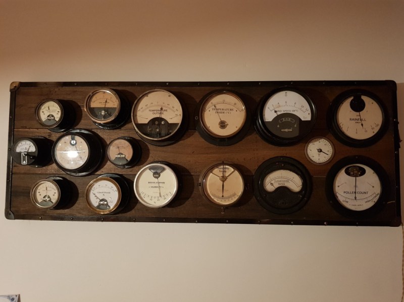
For most of us, getting weather information is as trivial as unlocking a smartphone or turning on a computer and pointing an app or browser at one’s weather site of choice. This is all well and good, but it lacks a certain panache that old weather stations had with their analog dials and stained wood cases. The weather station that [BuildComics] created marries both this antique aesthetic with modern weather data availability, and then dials it up a notch for this enormous analog weather station build.
The weather station uses 16 discrete dials, each modified with a different label for the specific type of data displayed. Some of them needed new glass, and others also needed coils to be modified to be driven with a lower current than they were designed as well, since each would be driven by one of two Arduinos in this project. Each are tied to a microcontroller output via a potentiometer which controls the needle’s position for the wildly different designs of meter. The microcontrollers themselves get weather information via the internet, which allows for about as up-to-date information about the weather as one could gather first-hand.
The amount of customization of these old meters is impressive, and what’s even more impressive is the project’s final weight. [BuildComics] reports that it took two people just to lift it onto the wall mount, which is not surprising given the amount of iron in some of these old analog meters. And, although not as common in the real world anymore, these old antique meters have plenty of repurposed uses beyond weather stations as well.
This is a quick start guide for the Four Digit Seven Segment Display Module and Enclosure from PMD Way. This module offers a neat and bright display which is ideal for numeric or hexadecimal data. It can display the digits 0 to 9 including the decimal point, and the letters A to F. You can also control each segment individually if desired.
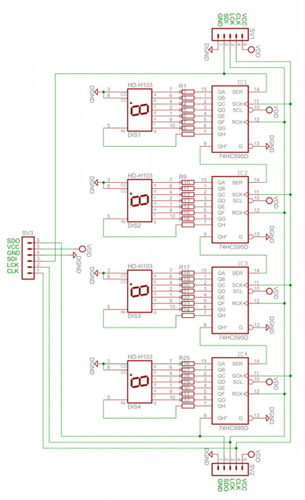
Each module contains four 74HC595 shift registers – once of each controls a digit. If you carefully remove the back panel from the enclosure, you can see the pin connections:
If you’re only using one display, use the group of pins at the centre-bottom of the board. From left to right the connections are:
Data out (ignore for single display use)
VCC – connect to a 3.3V or 5V supply
GND – connect to your GND line
SDI – data in – connect to the data out pin on your Arduino/other board
LCK – latch – connect to the output pin on your Arduino or other board that will control the latch
CLK – clock – connect to the output pin on your Arduino or other board that will control the clock signal
For the purposes of our Arduino tutorial, connect VCC to the 5V pin, GND to GND, SDI to D11, LCK to D13 and CLK to D12.
If you are connecting more than one module, use the pins on the left- and right-hand side of the module. Start with the connections from your Arduino (etc) to the right-hand side, as this is where the DIN (data in) pin is located.
Then connect the pins on the left-hand side of the module to the right-hand side of the new module – and so forth. SDO (data out) will connect to the SDI (data in) – with the other pins being identical for connection.
The module schematic is shown below:
Arduino Example Sketch
Once you have made the connections to your Arduino as outlined above, upload the following sketch:
// Demonstration Arduino sketch for four digit, seven segment display with enclosure
// https://pmdway.com/collections/7-segment-numeric-leds/products/four-digit-seven-segment-display-module-and-enclosure
int latchPin = 13;   // connect to LCK pin
intclockPin = 12;   // connect to CLK pin
intdataPin = 11;    // connect to SDI pin

int LED_SEG_TAB[]={
  0xfc,0x60,0xda,0xf2,0x66,0xb6,0xbe,0xe0,0xfe,0xf6,0x01,0xee,0x3e,0x1a,0x7a,0x9e,0x8e,0x01,0x00};
//0     1    2     3    4    5    6    7    8    9   dp   .    a    b    c    d    e    f   off

void setup()
{
  //set pins to output so you can control the shift register
  pinMode(latchPin, OUTPUT);
  pinMode(clockPin, OUTPUT);
  pinMode(dataPin, OUTPUT);
}

void displayNumber(int value, boolean leadingZero)
// break down "value" into digits and store in a,b,c,d
{
  int a,b,c,d;
  a = value / 1000;
  value = value % 1000;
  b = value / 100;
  value = value % 100;
  c = value / 10;
  value = value % 10;
  d = value;

  if (leadingZero==false) // removing leading zeros
  {
    if (a==0 && b>0)                  {
      a = 18;
    }
    if (a==0 && b==0 && c>0)          {
      a = 18;
      b = 18;
    }
    if (a==0 && b==0 && c==0)         {
      a = 18;
      b = 18;
      c = 18;
    }
    if (a==0 && b==0 && c==0 && d==0) {
      a = 18;
      b = 18;
      c = 18;
      d = 18;
    }
  }

  digitalWrite(latchPin, LOW);
  shiftOut(dataPin, clockPin, LSBFIRST, LED_SEG_TAB[d]);
  shiftOut(dataPin, clockPin, LSBFIRST, LED_SEG_TAB[c]);
  shiftOut(dataPin, clockPin, LSBFIRST, LED_SEG_TAB[b]);
  shiftOut(dataPin, clockPin, LSBFIRST, LED_SEG_TAB[a]);
  digitalWrite(latchPin, HIGH);
}

void allOff() // turns off all segments
{
  digitalWrite(latchPin, LOW);
  shiftOut(dataPin, clockPin, LSBFIRST, 0);
  shiftOut(dataPin, clockPin, LSBFIRST, 0);
  shiftOut(dataPin, clockPin, LSBFIRST, 0);
  shiftOut(dataPin, clockPin, LSBFIRST, 0);
  digitalWrite(latchPin, HIGH);
}

void loop()
{
  for (int z=900; z<=1100; z++)
  {
    displayNumber(z, false);
    delay(10);
  }
  delay(1000);
  for (int z=120; z>=0; --z)
  {
    displayNumber(z, true);
    delay(10);
  }
  delay(1000);

  digitalWrite(latchPin, LOW);
  shiftOut(dataPin, clockPin, LSBFIRST, LED_SEG_TAB[14]);
  shiftOut(dataPin, clockPin, LSBFIRST, LED_SEG_TAB[13]);
  shiftOut(dataPin, clockPin, LSBFIRST, LED_SEG_TAB[12]);
  shiftOut(dataPin, clockPin, LSBFIRST, LED_SEG_TAB[11]);
  digitalWrite(latchPin, HIGH);

  delay(1000);

  digitalWrite(latchPin, LOW);
  shiftOut(dataPin, clockPin, LSBFIRST, LED_SEG_TAB[16]);
  shiftOut(dataPin, clockPin, LSBFIRST, LED_SEG_TAB[15]);
  shiftOut(dataPin, clockPin, LSBFIRST, LED_SEG_TAB[14]);
  shiftOut(dataPin, clockPin, LSBFIRST, LED_SEG_TAB[13]);
  digitalWrite(latchPin, HIGH);
  delay(1000);

  digitalWrite(latchPin, LOW);
  shiftOut(dataPin, clockPin, LSBFIRST, LED_SEG_TAB[0]);
  shiftOut(dataPin, clockPin, LSBFIRST, LED_SEG_TAB[1]);
  shiftOut(dataPin, clockPin, LSBFIRST, LED_SEG_TAB[2]);
  shiftOut(dataPin, clockPin, LSBFIRST, LED_SEG_TAB[3]+1);
  digitalWrite(latchPin, HIGH);
  delay(1000);

  digitalWrite(latchPin, LOW);
  shiftOut(dataPin, clockPin, LSBFIRST, LED_SEG_TAB[7]);
  shiftOut(dataPin, clockPin, LSBFIRST, LED_SEG_TAB[6]+1);
  shiftOut(dataPin, clockPin, LSBFIRST, LED_SEG_TAB[5]);
  shiftOut(dataPin, clockPin, LSBFIRST, LED_SEG_TAB[4]);
  digitalWrite(latchPin, HIGH);
  delay(1000);
}
After a moment you should see the display spring into action in the same way as in the demonstration video:
How does it work?
First we define which digital output pins are used for latch, clock and data on lines four to six. On line eight we have created an array which contains values that are sent to the shift registers in the module to display the possible digits and letters. For example, the first – 0xfc – will activate the segments to display a zero, 0x7a for the letter C, and so on.
From line 20 we’ve created a custom function that is used to send a whole number between zero and 9999 to the display. To do so, simply use:
void displayNumber(value, true/false);
where value is the number to display (or variable containing the number) – and the second parameter of true or false. This controls whether you have a leading zero displayed – true for yes, false for no.
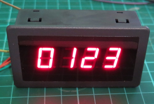
For example, to display “0123” you would use:
displayNumber(123, true);
… which results with:
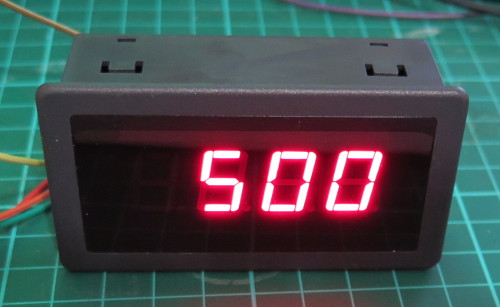
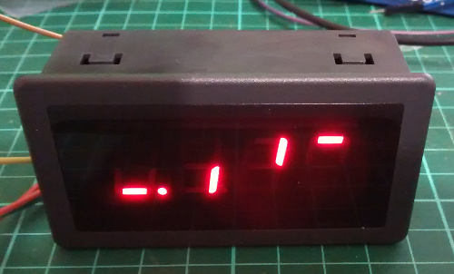
or to display “500” you would use:
displayNumber(500, false);
… which results with:
To turn off all the digits, you need to send zeros to every bit in the shift register, and this is accomplished with the function in the sketch called
allOff();
What about the decimal point?
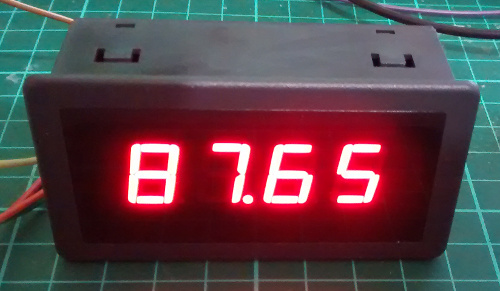
To turn on the decimal point for a particular digit, add 1 to the value being sent to a particular digit. Using the code from the demonstration sketch to display 87.65 you would use:
In-depth explanation of how the module is controlled
As shown in the schematic above, each digit is controlled by a 74HC595 shift register. Each shift register has eight digital outputs, each of which control an individual segment of each digit. So by sending four bytes of data (one byte = eight bits) you can control each segment of the display.
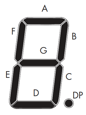
Each digit’s segments are mapped as follows:
And the outputs from each shift register match the order of segments from left to right. So outputs 0~7 match A~G then decimal point.
For example, to create the number seven with a decimal point, you need to turn on segments A, B, C and DP – which match to the shift register’s outputs 0,1,2,8.
Thus the byte to send to the shift register would be 0b11100001 (or 225 in decimal or 0xE1 in hexadecimal).
Every time you want to change the display you need to re-draw all four (or more if more than one module is connected) digits – so four bytes of data are sent for each display change. The digits are addressed from right to left, so the first byte send is for the last digit – and the last byte is for the first digit.
There are three stages of updating the display.
Set the LCK (latch) line low
Shift out four bytes of data from your microcontroller
Note how the bytes in binary match the map of the digits and their position. For example, the first byte sent was for the fourth digit, and the segment A was turned on. And that’s all there is to it – a neat and simple display.
This post brought to you by pmdway.com – everything for makers and electronics enthusiasts, with free delivery worldwide.
To keep up to date with new posts at tronixstuff.com, please subscribe to the mailing list in the box on the right, or follow us on twitter @tronixstuff.
[Mike Clifford] of [Modustrial Maker] had not one, not two, but five friends call him to announce that their first children were on the way, and he was inspired to build them a Bluetooth speaker with a unique LED matrix display as a fitting gift. Meant to not only entertain guests, but to audio-visually stimulate each of their children to promote neurological development.
Picking up and planing down rough maple planks, [Clifford] built a mitered box to house the components before applying wood finish. The brain inside the box is an Arduino Mega — or a suitable clone — controlling a Dayton Bluetooth audio and 2x15W amp board. In addition to the 19.7V power supply, there’s a step down converter for the Mega, and a mic to make the LED matrix sound-reactive. The LED matrix is on a moveable baffle to adjust the distance between it and a semi-transparent acrylic light diffuser. This shifts the light between sharp points or a softer, blended look — perfect for the scrolling Matrix text and fireplace effects! Check it out!
[Clifford]’s Arduino code is up on GitHub for anyone else out there with friends who are expecting. You never know when your own childhood Fisher-Price cassette players from back in the day might come in handy.
[Robin Reiter] needed a better way to show off his work. He previously converted an electric TV stand into a full 360-degree display turntable, but it relied on an external power supply to get it spinning. It was time to give it an upgrade.
Putting his spacial organization skills to work, [Reiter] has crammed a mini OLED display, rotary encoder, a LiPo 18650 battery and charging circuit, a pair of buck converters, a power switch, and an Arduino pro mini into the small control console. To further maximize space, [Reiter] stripped out the pin headers and wired the components together directly. It attaches to the turntable in question with magnets, so it can be removed out of frame, or for displaying larger objects!
When first powered on, the turntable holds in pause mode giving [Reiter] time to adjust the speed and direction. He also took the time to add an optical rotary encoder disk to the turntable and give the gearing a much needed cleaning. Check out the project video after the break!
[Reiter] is looking to add a timed stop feature, and — taking advantage of that rotary encoder — a rotate to target angle option, but it performs admirably at present.
We can see this display coming in handy for any 3D scanning needs too!
There’s building small computers — like the Raspberry Pi — and then there’s building small computers — like this Desktop Viewer from Star Trek.
[Monta Elkins] is using a Beetle for this project; it’s an Arduino clone, hosting the ATMega32U4 microcontroller, with a unique feature that allows you to twist connecting wires to secure them to the board. Instead, [Elkins] went with the logical choice of soldering them. For a display, he used a SPI serial OLED 128 x 64 monochrome screen which he has cycling through a number of iconic Star Trek TOS symbols and animations. The images were converted into PROGMEM — which gets loaded into flash memory — before finally being uploaded to the Beetle.
Following some fine 3D print work in ABS plastic which rendered the Desktop Viewer’s case, [Elkins] used acetone to solvent-weld the pieces together and applied a quick coat of paint to finish it off. This little replica would make a great desktop gadget as it requires a micro-USB to power the device.
The renaissance of Nixie tube popularity amid the nostalgia surrounding older tech has made them almost prohibitively expensive for individual projects. Seeing an opportunity to modernize the beloved devices, [Connor Nishijima] has unleashed this new, LED edge-lit display that he has dubbed Lixie.
We featured his prototype a few years ago. That design used dots to make up each character but this upgrade smooths that out with sleek lines and a look one would almost expect from a professional device — or at the very least something you’d see in a cyberpunk near-future. The color-changing Neopixel LEDs — moderated by a cleverly designed filter — allow for customization to your heart’s content, and the laser-cut acrylic panes allow for larger displays to be produced with relative ease.
The image above (and the video below) show two revisions of the most recent Lixie prototypes. There is a huge improvement on the right, as the digits are now outlines instead of single strokes and engraved instead of cut completely through the acrylic. The difference if phenomenal, and in our opinion move the “back to the drawing board” effect to “ready for primetime”. [Connor] and his team are working on just that, with a Tindie preorder in place for the first production-ready digits to roll off their line.
Considering that Nixie Tubes were originally considered too expensive for mass-produced items like clocks, it’s ironic they’re seeing a revival in hobbyist projects for just that purpose. Lixie, then, may fit the purpose for those seeing a cheaper solution without sacrificing on the quality of the result. The design is fully open-source, so get to hacking!
For a suitably cyberpunk application of a Nixie tube, check out this motorcycle speedometer. Oh, and lest you think we’re duplicating ourselves, there was another edge-lit Nixie-alike project featured here just a few weeks ago. Seems good ideas come in waves.
In preparation for Makerfaire, [hwhardsoft] needed to throw together some demos. So they dug deep and produced this unique display.
The display uses two synchronized peristaltic pumps to push water and red paraffin through a tube that switches back over itself in a predictable fashion. As visible in the video after the break, the pumps go at it for a few minutes producing a seemingly random pattern. The pattern coalesces at the end into a short string of text. The text is unfortunately fairly hard to read, even on a contrasting background. Perhaps an application of UV dye could help?
Once the message has been displayed, the water and paraffin drop back into the holding tank as the next message is queued up. The oil and water separate just like expected and a pump at the level of each fluid feeds it back into the system.
We were deeply puzzled at what appeared to be an Arduino mounted on a DIN rail for use in industrial settings, but then discovered that this product is what [hwhardsoft] built the demo to sell. We can see some pretty cool variations on this technique for art displays.
Vacuum fluorescent displays look really kinda fancy and cool to me, I really love the blue-breen color. That’s why I decided to write this Instructable about a clock based on this technology. This is my first instructable here, showing you how I have designed built my clock and how you can build yourself exactly the same or a similar clock that utilizes the VFD display. I’m not a native speaker – just for you to know if you’re wondering why some sentences might make no sense at all.
Vacuum fluorescent displays look really kinda fancy and cool to me, I really love the blue-breen color. That’s why I decided to write this Instructable about a clock based on this technology. This is my first instructable here, showing you how I have designed built my clock and how you can build yourself exactly the same or a similar clock that utilizes the VFD display. I’m not a native speaker – just for you to know if you’re wondering why some sentences might make no sense at all.
Initial testing. Ignore the humidity sensor, that was for something else.
The vacuum gauge outputs 0-10VDC. This had to be changed to a 0-5VDC range using a potential divider so it was compatible with the Arduino. Initial build used a 10k pot in place of a vacuum gauge to make it simpler.
Planet Arduino is, or at the moment is wishing to become, an aggregation of public weblogs from around the world written by people who develop, play, think on Arduino platform and his son. The opinions expressed in those weblogs and hence this aggregation are those of the original authors. Entries on this page are owned by their authors. We do not edit, endorse or vouch for the contents of individual posts. For more information about Arduino please visit www.arduino.cc
You are currently browsing the archives for the display category.