Posts | Comments

Planet Arduino

Archive for the ‘SPI’ Category

Strobe Remote

If you want to take a photograph with a professional look, proper lighting is going to be critical. [Richard] has been using a commercial lighting solution in his studio. His Lencarta UltraPro 300 studio strobes provide adequate lighting and also have the ability to have various settings adjusted remotely. A single remote can control different lights setting each to its own parameters. [Richard] likes to automate as much as possible in his studio, so he thought that maybe he would be able to reverse engineer the remote control so he can more easily control his lighting.

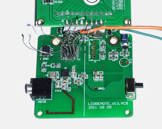
[Richard] started by opening up the remote and taking a look at the radio circuitry. He discovered the circuit uses a nRF24L01+ chip. He had previously picked up a couple of these on eBay, so his first thought was to just promiscuously snoop on the communications over the air. Unfortunately the chips can only listen in on up to six addresses at a time, and with a 40-bit address, this approach may have taken a while.

Not one to give up easily, [Richard] chose a new method of attack. First, he knew that the radio chip communicates to a master microcontroller via SPI. Second, he knew that the radio chip had no built-in memory. Therefore, the microcontroller must save the address in its own memory and then send it to the radio chip via the SPI bus. [Richard] figured if he could snoop on the SPI bus, he could find the address of the remote. With that information, he would be able to build another radio circuit to listen in over the air.

Using an Open Logic Sniffer, [Richard] was able to capture some of the SPI communications. Then, using the datasheet as a reference, he was able to isolate the communications that stored information int the radio chip’s address register. This same technique was used to decipher the radio channel. There was a bit more trial and error involved, as [Richard] later discovered that there were a few other important registers. He also discovered that the remote changed the address when actually transmitting data, so he had to update his receiver code to reflect this.

The receiver was built using another nRF24L01+ chip and an Arduino. Once the address and other registers were configured properly, [Richard's] custom radio was able to pick up the radio commands being sent from the lighting remote. All [Richard] had to do at this point was press each button and record the communications data which resulted. The Arduino code for the receiver is available on the project page.

[Richard] took it an extra step and wrote his own library to talk to the flashes. He has made his library available on github for anyone who is interested.


Filed under: Arduino Hacks, radio hacks
Aug
03

SPI Transactions in Arduino

arduino, SPI Comments Off on SPI Transactions in Arduino 

scope-600x450

Paul over at DorkbotPDX writes:

For the last several weeks, I’ve been working on SPI transactions for Arduino’s SPI library, to solve conflicts that sometimes occur between multiple SPI devices when using SPI from interrupts and/or different SPI settings.
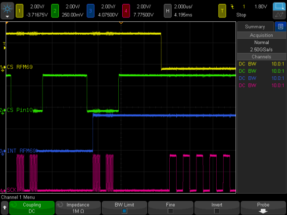
To explain, a picture is worth 1000 works. In this screenshot, loop() repetitively sends 2 bytes, where green is its chip select and red is the SPI clock. Blue is the interrupt signal (rising edge) from a wireless module. In this test, the interrupt happens at just the worst moment, during the first byte while loop() is using the SPI bus!
Without transactions, the wireless lib interrupt would immediately assert (active low) the yellow chip select while the green is still active low, then begin sending its data with both devices listening!

SPI Transactions in Arduino - [Link]

Aug
01

Arduino SPI Library Gains Transaction Support

arduino, arduino hacks, interrupts, jitter, Library, SPI Comments Off on Arduino SPI Library Gains Transaction Support 

Transaction SPI Timing

Transaction SPI Timing

To prevent data corruption when using multiple SPI devices on the same bus, care must be taken to ensure that they are only accessed from within the main loop, or from the interrupt routine, never both. Data corruption can happen when one device is chip selected in the main loop, and then during that transfer an interrupt occurs, chip selecting another device. The original device now gets incorrect data.

For the last several weeks, [Paul] has been working on a new Arduino SPI library, to solve these types of conflicts. In the above scenario, the new library will generate a blocking SPI transaction, thus allowing the first main loop SPI transfer to complete, before attempting the second transfer. This is illustrated in the picture above, the blue trace rising edge is when the interrupt occurred, during the green trace chip select. The best part, it only affects SPI, your other interrupts will still happen on time. No servo jitter!

This is just one of the new library features, check out the link above for the rest. [Paul] sums it up best: “protects your SPI access from other interrupt-based libraries, and guarantees correct setting while you use the SPI bus”.


Filed under: Arduino Hacks
May
02

Digispark Pro – tiny, Arduino ready, mobile & usb dev board!

arduino, Digispark, Digispark Pro, i2c, SPI, uart, USB Comments Off on Digispark Pro – tiny, Arduino ready, mobile & usb dev board! 

Digispark Pro - The tiny Arduino IDE ready, usb and mobile dev board and ecosystem – cheap enough to leave in any project! Wi-fi, BLE, and 25+ shields!

Serial over USB debugging, USB programmable, 14 i/o, SPI, I2C, UART, USB Device Emulation, Mobile Development Ready, Optional BT, BLE, Mesh, and Wi-Fi.

The super small, dirt cheap, always open source, Arduino compatible, USB (and Mobile and Wireless!) development (and production) platform, and follow-up to the original Digispark.

Easier to use, more pins, more program space, more features, more reliable – supporting the entire existing Digispark ecosystem of 25+ shields and adding Wi-Fi, Bluetooth, BLE shields and more! Ready for all your projects – including mobile hardware development! All still super affordable!

The Digispark Pro Ecosystem is the cheapest, Arduino compatible development platform for Mobile and Wireless hardware development.

Digispark Pro – tiny, Arduino ready, mobile & usb dev board! - [Link]

May
02

LED aquarium lighting with an Arduino based PWM timer

arduino, cree, DS3234, Microcontroller, PWM, SPI, XP-G R5 Comments Off on LED aquarium lighting with an Arduino based PWM timer 

aquarium_light_timer_1024x

by Kalle Hyvönen:

I bought a small aquarium (54l) as an impulse buy and I needed some lights for it, so naturally I wanted to use LEDs. I also needed a timer for the lights. I also wanted the lights to fade in and out when they were going on or off as a cool effect.

I ordered four Cree XP-G R5 LEDs (cool white, apparently too warm of a light will cause algae growth) and a one amp (switching) constant current supply (with PWM support) from LED-tech.de. I had some Maxim DS3234 real-time clocks with a serial bus (SPI) which looked easy to implement so I decided to use one. I also had one spare Arduino board so that was going to be my microcontroller of choice. I used a laptop power supply as the power source.

LED aquarium lighting with an Arduino based PWM timer - [Link]

Dec
06

The 86Duino Zero Runs Linux on x86

86Duino, 86Duino Zero, arduino, ethernet, i2c, ipc, Linux, microSD, PCIE, RTOS, SPI, Vortex86EX, x86, xISA Comments Off on The 86Duino Zero Runs Linux on x86 

86Duino_ZERO-45D

DM&P has been producing low-power, x86-based Vortex processors for the embedded market for over ten years. Now in a nod to the Arduino market they have released the 86Duino Zero, a low-cost Arduino Leonardo sized board powered by their latest 300 MHz SoC Vortex86EX Processor.

This is a fully static 32-bit x86 processor board compatible with Windows OS, Linux and most other popular 32-bit RTOS. It integrates a PCIE bus, DDR3, ROM controller, xISA, I2C, SPI, IPC (Internal Peripheral Controllers with DMA and interrupt timer/counter included). The 86Duino Zero’s ports include USB 2.0 host and device coastline ports, a 10/100 Ethernet port and a microSD slot on the bottom of the board. The Zero’s baseboard also provides a 7-12V power jack, a reset button and a PCIe expansion connector.

The Zero supplies 14 digital I/O pins, half of which can provide 32-bit resolution PWM outputs and six 11-bit analog input pins. Each standard I/O pin supplies 16 mA while the 3.3 V pins can supply up to 400 mA. Like the Intel Galileo development board announced several weeks ago the 86Duino Zero marries Intel architecture to the Arduino platform. Its $39 price tag makes it an attractive proposition. [via]

The 86Duino Zero Runs Linux on x86 - [Link]

Aug
19

Rescuing an SD card with an Arduino

arduino hacks, data recovery, sd, sd card, SDIO, SPI Comments Off on Rescuing an SD card with an Arduino 

SD

A few days ago, one of [Severin]‘s SD cards died on him, Instead of trashing the card, he decided to investigate what was actually wrong with the card and ended up recovering most of the data using an Arduino and an immense amount of cleverness.

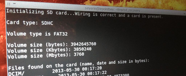
SD cards can be accessed with two modes. The first is the SDIO mode, which is what cameras, laptops, and other card readers use. The second mode is SPI mode. SPI is slower, but much, much simpler. It turned out the SDIO mode on [Severin]‘s card was broken, but accessing it with an Arduino and SPI mode worked. There was finally hope to get files off this damaged card.

[Severin] used a few sketches to dump the data on the SD card to his computer. The first looked at the file system and grabbed a list of files contained on the card. The second iterated over the file system and output all the files in hex over the serial port. With a bit of Python, [Severin] was able to reconstruct a few files that were previously lost forever.

Even though the SD card was completely inaccessible with a normal card reader, [Severin] was able to get a few files off the card. All the sketches and Python scripts are available on the Githubs, ready to recover files from your broken SD cards.


Filed under: Arduino Hacks
Jul
26

Using an Arduino to Control or Test an SPI electronic device

arduino, SPI, Test/Measurements Comments Off on Using an Arduino to Control or Test an SPI electronic device 

FMKUVOBGZFUT2AK.LARGE

techshopdude @ instructables.com writes:

There are many electronic devices that use the SPI bus, or Serial Peripheral Interface bus, for communications (e.g. various sensors, LCD displays, digital potentiometers, D/A and A/D converters, wireless transmitters and receivers, audio volume controls). The devices receive data serially from a microcontroller using a 3-wire set-up that includes a chip select signal (usually titled CS – when this signal is at logic 0, a chip recognizes it will be receiving or sending data), a clock signal for clocking the serial data into the device, and the serial data stream itself.

Using an Arduino to Control or Test an SPI electronic device - [Link]

Feb
03

A Voice Shield for Arduino – Give Voice to your Ideas!

arduino, shield, SPI, voice Comments Off on A Voice Shield for Arduino – Give Voice to your Ideas! 

Audio-Shield5

This Voice shield can be useful to integrate voice messages in alarm systems, to implement generic I/O controls in home automation or even in home security applications: something like playing an alert when a person or a vehicle approaches any given protected area. The use cases are many and limited only by your imagination!

While this shield can operate stand-alone, it can be better managed through and SPI interface: by connecting this with Arduino it can take control of the speech synthesis.

A Voice Shield for Arduino – Give Voice to your Ideas! - [Link]

Feb
03

Netduino and MAX721 interfacing for driving seven segment LED displays

arduino, LED, MAX721, MAX7219, Netduino, SPI Comments Off on Netduino and MAX721 interfacing for driving seven segment LED displays 

Day4_SevenSegment_Top

Here’s a tutorial on interfacing MAX7219 LED driver chip to Netduino platform for driving 8 digits of seven segment LED displays. The .NET Micro FramWork provides a SPI class that is used to send display data to the MAX7219 chip through a SPI serial interface.

Netduino and MAX721 interfacing for driving seven segment LED displays - [Link]


  • Newsletter

    Sign up for the PlanetArduino Newsletter, which delivers the most popular articles via e-mail to your inbox every week. Just fill in the information below and submit.

  • Like Us on Facebook