Posts | Comments

Planet Arduino

Archive for the ‘Beginner’ Category

10percentOff

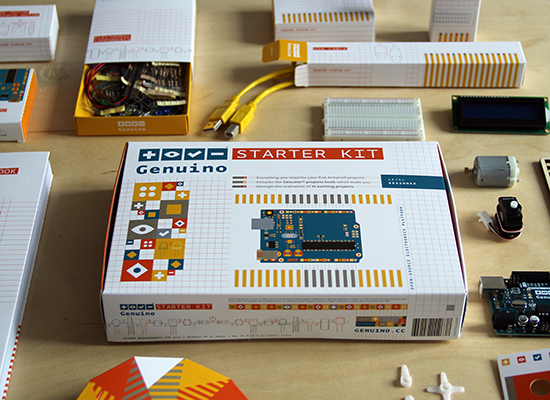
This is your chance to put your hands on Arduino Starter Kit or Genuino Starter Kit with a 10 % discount*.

The promotion is active on our online stores for a limited time: April 20th and 21st. Get it now  inserting the coupon code SPRING at checkout!

The Starter Kit is based on lessons Arduino’s founders have learned teaching their own classes: if you start with the assumption that learning to make digital technologies is simple and accessible, you can really make it so.

The package includes a Uno board and the components you need to make 15 fun projects following the step-by-step tutorials on the Project Book. The book walks you through the basics in a hands-on way, with creative projects you build by learning. Once you’ve mastered the basics, you’ll have a palette of software and circuits that you can use to create something beautiful, and useful!

GenuinoStarter_Blog

*Acquistando dall’Italia il coupon e’ valido esclusivamente selezionando Genuino Starter Kit in lingua italiana

* If you purchase from Italy the coupon is valid only selecting Genuino Starter Kit in italian language .

Oct
28

SAINTCON Badge (Badge Hacking for Mortals)

arduino hacks, badge, Beginner, cons, crypto, puzzle, saintcon Comments Off on SAINTCON Badge (Badge Hacking for Mortals) 

saintcon-badge

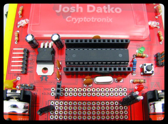
[Josh] attended his first SAINTCON this weekend before last and had a great time participating in the badge hacking challenge.

The 2014 SAINTCON is only the second time that the conference has been open to the public. They give out conference badges which are just an unpopulated circuit board. This makes a lot of sense if you figure the number of people who actually hack their badges at conferences is fairly low. So he headed off to the hardware hacking village to solder on the components by hand — it’s an Arduino clone.

This is merely the start of the puzzle. We really like that the published badge resources include a crash course on how to read a schematic. The faq also attests that the staff won’t solder it for you and to get your microcontroller you have to trade in your security screw (nice touch). Once up and running you need to pull up the terminal on the chip and solve the puzzles in the firmware’s menu system. This continues with added hardware for each round: an IR receiver, thermistor, EEPROM, great stuff if you’re new to microcontrollers.

[Josh] mentions that this is nothing compared to the DEFCON badge. Badge hacking at DEFCON is **HARD**; and that’s good. It’s in the top-tier of security conferences and people who start the badge-solving journey expect the challenge. But if you’re not ready for that level of puzzle, DEFCON does have other activities like Darknet. That is somewhere in the same ballpark as the SAINTCON badge — much more friendly to those just beginning to developing their crypto and hardware hacking prowess. After all, everyone’s a beginner at some point. If that’s you quit making excuses and dig into something fun like this!


Filed under: Arduino Hacks, cons
MCjiWaqjfHqqWF4XCombine an Arduino, an ultransonic distance sensor, and some common components to build a classic "hot/cold" project. Once assembled, we'll walk through the software "sketch" loaded onto our Arduino, and experiment with three variations of the "hot/cold" theme, all the while using the same circuit.

Read the full article on MAKE

Nov
08

LED Patterns Using DIP Switch and Arduino

arduino, Beginner, code, DIP switch, sketch, video Comments Off on LED Patterns Using DIP Switch and Arduino 

When I posted the “LED Control Using DIP Switch” sketch last year (a simple setup the turned on the LED corresponding to that switch position), I also had a slightly modified version of it in which the DIP switch controlled six different light patterns on the LEDs (scroll right, left, in, out, back and forth and random). It presented a “cleaned-up” version of the code using for loops and compared it to the “long-hand” version, showing the trade-off between ease of understanding and conciseness. Except that… I forgot to post it.

Last week someone contacted me asking a question about a similar project he is working on and when I wanted to refer him to this modified sketch I realized it wasn’t on the blog. (Here’s the original sketch and schematic for reference).

What follows below is the missing blog post (not anymore), a comparison between the more readable sketch (easier for beginners to understand) and the more concise version, in a series of snippets showing the main differences between the two versions of the sketch.

The concise version generates a binary sketch that occupies approximately 25% less memory and is almost half as long in lines of code. The entire source code listings are at the very bottom of this post.

Note: the line above each snippet reflects the modification that shortened the sketch.

1) not using #define directives for the LED and switch pins on the Arduino in order to use for loops:

    } else {
     // default: off
     digitalWrite(LED1, LOW);
     digitalWrite(LED2, LOW);
     digitalWrite(LED3, LOW);
     digitalWrite(LED4, LOW);
     digitalWrite(LED5, LOW);
     digitalWrite(LED6, LOW);
   }
    } else {
     // default: off
     for (i = 13; i >= 8; i--) {
       digitalWrite(i, LOW);
     }


2) using a state variable array (and consequently a for loop) as opposed to individual state variables:

   s1state = digitalRead(S1);
   s2state = digitalRead(S2);
   s3state = digitalRead(S3);
   s4state = digitalRead(S4);
   s5state = digitalRead(S5);
   s6state = digitalRead(S6);
   for (i = 0, j = 7; i < 6, j >= 2; i++, j--) {
     state[i] = digitalRead(j);
   }


3) if (x) versus if (x == 1) (when x is either 0 or 1, then the (x == 1) expression can be written as simply (x)):

    } else if (s5state == 1) {
     // scroll back and forth
    } else if (state[4]) {
     // scroll back and forth


4) long, repetitive code to randomly turn on or not each LED (for a random duration up to 300 milliseconds) replaced with for loop:

    } else if (s6state == 1) {
     // random
     randomSeed(analogRead(3));
     onoroff = random(0, 2);
     millisecs = random(0, 301);
     digitalWrite(LED1, onoroff);
     delay(millisecs);
     randomSeed(analogRead(3));
     onoroff = random(0, 2);
     millisecs = random(0, 301);
     digitalWrite(LED2, onoroff);
     delay(millisecs);
     randomSeed(analogRead(3));
     onoroff = random(0, 2);
     millisecs = random(0, 301);
     digitalWrite(LED3, onoroff);
     delay(millisecs);
     randomSeed(analogRead(3));
     onoroff = random(0, 2);
     millisecs = random(0, 301);
     digitalWrite(LED4, onoroff);
     delay(millisecs);
     randomSeed(analogRead(3));
     onoroff = random(0, 2);
     millisecs = random(0, 301);
     digitalWrite(LED5, onoroff);
     delay(millisecs);
     randomSeed(analogRead(3));
     onoroff = random(0, 2);
     millisecs = random(0, 301);
     digitalWrite(LED6, onoroff);
     delay(millisecs);
   }
    } else if (state[5]) {
     // random
     for (i = 13; i >= 8; i--) {
       randomSeed(analogRead(i - 8));
       onoroff = random(0, 2);
       millisecs = random(0, 301);
       digitalWrite(i, onoroff);
       delay(millisecs);
     }
   }


Here’s the full long version:

  • Binary sketch size: 3654 bytes
  • Code size was sacrificed in order to improve readability for beginners
  • Sketch length: 205 lines
  // www.TinkerHobby.com
  // Natalia Fargasch Norman
  // LED control via DIP switches

  // Arduino pins used for the LEDs
  #define LED1 13
  #define LED2 12
  #define LED3 11
  #define LED4 10
  #define LED5 9
  #define LED6 8

  // Arduino pins used for the switches
  #define S1 7
  #define S2 6
  #define S3 5
  #define S4 4
  #define S5 3
  #define S6 2

  // State of each switch (0 or 1)
  int s1state;
  int s2state;
  int s3state;
  int s4state;
  int s5state;
  int s6state;

  // Random values for LED state and delay
  long onoroff;
  long millisecs;

  void setup() {
    // pins for LEDs are outputs
    pinMode(LED1, OUTPUT);
    pinMode(LED2, OUTPUT);
    pinMode(LED3, OUTPUT);
    pinMode(LED4, OUTPUT);
    pinMode(LED5, OUTPUT);
    pinMode(LED6, OUTPUT);
    // pins for switches are inputs
    pinMode(S1, INPUT);
    pinMode(S2, INPUT);
    pinMode(S3, INPUT);
    pinMode(S4, INPUT);
    pinMode(S5, INPUT);
    pinMode(S6, INPUT);
  }

  void loop() {
    s1state = digitalRead(S1);
    s2state = digitalRead(S2);
    s3state = digitalRead(S3);
    s4state = digitalRead(S4);
    s5state = digitalRead(S5);
    s6state = digitalRead(S6);
    if (s1state == 1) {
      // scroll right
      digitalWrite(LED1, HIGH);
      delay(250);
      digitalWrite(LED1, LOW);
      digitalWrite(LED2, HIGH);
      delay(250);
      digitalWrite(LED2, LOW);
      digitalWrite(LED3, HIGH);
      delay(250);
      digitalWrite(LED3, LOW);
      digitalWrite(LED4, HIGH);
      delay(250);
      digitalWrite(LED4, LOW);
      digitalWrite(LED5, HIGH);
      delay(250);
      digitalWrite(LED5, LOW);
      digitalWrite(LED6, HIGH);
      delay(250);
      digitalWrite(LED6, LOW);
    } else if (s2state == 1) {
      // scroll left
      digitalWrite(LED6, HIGH);
      delay(250);
      digitalWrite(LED6, LOW);
      digitalWrite(LED5, HIGH);
      delay(250);
      digitalWrite(LED5, LOW);
      digitalWrite(LED4, HIGH);
      delay(250);
      digitalWrite(LED4, LOW);
      digitalWrite(LED3, HIGH);
      delay(250);
      digitalWrite(LED3, LOW);
      digitalWrite(LED2, HIGH);
      delay(250);
      digitalWrite(LED2, LOW);
      digitalWrite(LED1, HIGH);
      delay(250);
      digitalWrite(LED1, LOW);
    } else if (s3state == 1) {
      // scroll in
      digitalWrite(LED1, HIGH);
      digitalWrite(LED6, HIGH);
      delay(250);
      digitalWrite(LED1, LOW);
      digitalWrite(LED6, LOW);
      digitalWrite(LED2, HIGH);
      digitalWrite(LED5, HIGH);
      delay(250);
      digitalWrite(LED2, LOW);
      digitalWrite(LED5, LOW);
      digitalWrite(LED3, HIGH);
      digitalWrite(LED4, HIGH);
      delay(250);
      digitalWrite(LED3, LOW);
      digitalWrite(LED4, LOW);
    } else if (s4state == 1) {
      // scroll out
      digitalWrite(LED3, HIGH);
      digitalWrite(LED4, HIGH);
      delay(250);
      digitalWrite(LED3, LOW);
      digitalWrite(LED4, LOW);
      digitalWrite(LED2, HIGH);
      digitalWrite(LED5, HIGH);
      delay(250);
      digitalWrite(LED2, LOW);
      digitalWrite(LED5, LOW);
      digitalWrite(LED1, HIGH);
      digitalWrite(LED6, HIGH);
      delay(250);
      digitalWrite(LED1, LOW);
      digitalWrite(LED6, LOW);
    } else if (s5state == 1) {
      // scroll back and forth
      digitalWrite(LED1, HIGH);
      delay(250);
      digitalWrite(LED1, LOW);
      digitalWrite(LED2, HIGH);
      delay(250);
      digitalWrite(LED2, LOW);
      digitalWrite(LED3, HIGH);
      delay(250);
      digitalWrite(LED3, LOW);
      digitalWrite(LED4, HIGH);
      delay(250);
      digitalWrite(LED4, LOW);
      digitalWrite(LED5, HIGH);
      delay(250);
      digitalWrite(LED5, LOW);
      digitalWrite(LED6, HIGH);
      delay(250);
      digitalWrite(LED6, LOW);
      digitalWrite(LED5, HIGH);
      delay(250);
      digitalWrite(LED5, LOW);
      digitalWrite(LED4, HIGH);
      delay(250);
      digitalWrite(LED4, LOW);
      digitalWrite(LED3, HIGH);
      delay(250);
      digitalWrite(LED3, LOW);
      digitalWrite(LED2, HIGH);
      delay(250);
      digitalWrite(LED2, LOW);
    } else if (s6state == 1) {
      // random
      randomSeed(analogRead(3));
      onoroff = random(0, 2);
      millisecs = random(0, 301);
      digitalWrite(LED1, onoroff);
      delay(millisecs);
      randomSeed(analogRead(3));
      onoroff = random(0, 2);
      millisecs = random(0, 301);
      digitalWrite(LED2, onoroff);
      delay(millisecs);
      randomSeed(analogRead(3));
      onoroff = random(0, 2);
      millisecs = random(0, 301);
      digitalWrite(LED3, onoroff);
      delay(millisecs);
      randomSeed(analogRead(3));
      onoroff = random(0, 2);
      millisecs = random(0, 301);
      digitalWrite(LED4, onoroff);
      delay(millisecs);
      randomSeed(analogRead(3));
      onoroff = random(0, 2);
      millisecs = random(0, 301);
      digitalWrite(LED5, onoroff);
      delay(millisecs);
      randomSeed(analogRead(3));
      onoroff = random(0, 2);
      millisecs = random(0, 301);
      digitalWrite(LED6, onoroff);
      delay(millisecs);
    } else {
      // default: off
      digitalWrite(LED1, LOW);
      digitalWrite(LED2, LOW);
      digitalWrite(LED3, LOW);
      digitalWrite(LED4, LOW);
      digitalWrite(LED5, LOW);
      digitalWrite(LED6, LOW);
    }
  }


And here’s the full “cleaned-up” version:

  • Binary sketch size: 2826 bytes
  • Sketch length: 119 lines
  // www.TinkerHobby.com
  // Natalia Fargasch Norman
  // LED control via DIP switches

  // Arduino pins used for the LEDs
  // LED1 13
  // LED2 12
  // LED3 11
  // LED4 10
  // LED5 9
  // LED6 8

  // Arduino pins used for the switches
  // S1 7
  // S2 6
  // S3 5
  // S4 4
  // S5 3
  // S6 2

  // State of each switch (0 or 1)
  int state[6];

  // Random values for LED state and delay
  long onoroff;
  long millisecs;

  // loop counters
  int i, j;

  // delay
  int d = 250;

  void setup() {
    // pins for LEDs are outputs
    // LEDs 1-6 on pins 13-8
    for (i = 13; i >= 8; i--) {
      pinMode(i, OUTPUT);
    }
    // pins for switches are inputs
    // switches 1-6 on pins 7-2
    for (i = 7; i >= 2; i--) {
      pinMode(i, INPUT);
    }
  }

  void loop() {
    for (i = 0, j = 7; i < 6, j >= 2; i++, j--) {
      state[i] = digitalRead(j);
    }

    if (state[0]) {
      // scroll right
      for (i = 13; i >= 8; i--) {
        digitalWrite(i, HIGH);
        delay(d);
        digitalWrite(i, LOW);
      }

    } else if (state[1]) {
      // scroll left
      for (i = 8; i <= 13; i++) {
         digitalWrite(i, HIGH);
         delay(d);
         digitalWrite(i, LOW);
       }

   } else if (state[2]) {
       // scroll in
       // light up LEDs on pins i and 8+(13-i)
       for (i = 13; i >= 11; i--) {
        digitalWrite(i, HIGH);
        digitalWrite(21 - i, HIGH);
        delay(d);
        digitalWrite(i, LOW);
        digitalWrite(21 - i, LOW);
      }

    } else if (state[3]) {
      // scroll out
      // light up LEDs on pins i and 8+(13-i)
      for (i = 11; i <= 13; i++) {
         digitalWrite(i, HIGH);
         digitalWrite(21 - i, HIGH);
         delay(d);
         digitalWrite(i, LOW);
         digitalWrite(21 - i, LOW);
       }

    } else if (state[4]) {
       // scroll back and forth
       for (i = 13; i >= 8; i--) {
        digitalWrite(i, HIGH);
        delay(d);
        digitalWrite(i, LOW);
      }
      for (i = 9; i <= 12; i++) {
        digitalWrite(i, HIGH);
        delay(d);
        digitalWrite(i, LOW);
      }

    } else if (state[5]) {
       // random
       for (i = 13; i >= 8; i--) {
        randomSeed(analogRead(i - 8));
        onoroff = random(0, 2);
        millisecs = random(0, 301);
        digitalWrite(i, onoroff);
        delay(millisecs);
      }      

    } else {
      // default: off
      for (i = 13; i >= 8; i--) {
        digitalWrite(i, LOW);
      }
    }
  }

Check out the video of this sketch in action.

LED Patterns Using DIP Switch and Arduino originally appeared on Tinker Hobby on November 8, 2011.

Sep
14

Arduino LED Control Using DIP Switch | Part 1

arduino, Beginner, DIP switch, LED, pins, project, serial communication Comments Off on Arduino LED Control Using DIP Switch | Part 1 

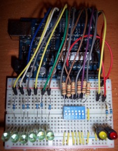
LED control using DIP switchThis is a very simple project that controls a set of LEDs using a DIP switch. The purpose of the sketch is to show the use of some Arduino serial communication functions, and to increase familiarity interfacing with digital I/O pins.

Two LEDs were connected to the RX and TX pins on the Arduino (digital pins 0 and 1), but remember to disconnect these pins while the sketch is being uploaded.

Parts list:

Sketch:

// www.TinkerHobby.com
// Natalia Fargasch Norman
// LED control via DIP switches

// Arduino pins used for the LEDs
#define LED1 13
#define LED2 12
#define LED3 11
#define LED4 10
#define LED5 9
#define LED6 8

// Arduino pins used for the switches
#define S1 7
#define S2 6
#define S3 5
#define S4 4
#define S5 3
#define S6 2

// State of each switch (0 or 1)
int s1state;
int s2state;
int s3state;
int s4state;
int s5state;
int s6state;

void setup() {
  // pins for LEDs are outputs
  pinMode(LED1, OUTPUT);
  pinMode(LED2, OUTPUT);
  pinMode(LED3, OUTPUT);
  pinMode(LED4, OUTPUT);
  pinMode(LED5, OUTPUT);
  pinMode(LED6, OUTPUT);
  // pins for switches are inputs
  pinMode(S1, INPUT);
  pinMode(S2, INPUT);
  pinMode(S3, INPUT);
  pinMode(S4, INPUT);
  pinMode(S5, INPUT);
  pinMode(S6, INPUT);
  // setup serial port
  Serial.begin(9600);
  Serial.println("Serial port open");
}

void loop() {
  s1state = digitalRead(S1);
  digitalWrite(LED1, s1state);
  s2state = digitalRead(S2);
  digitalWrite(LED2, s2state);
  s3state = digitalRead(S3);
  digitalWrite(LED3, s3state);
  s4state = digitalRead(S4);
  digitalWrite(LED4, s4state);
  s5state = digitalRead(S5);
  digitalWrite(LED5, s5state);
  s6state = digitalRead(S6);
  digitalWrite(LED6, s6state);
  Serial.print(s1state);
  Serial.print(s2state);
  Serial.print(s3state);
  Serial.print(s4state);
  Serial.print(s5state);
  Serial.print(s6state);
  Serial.println();
}

Here is the schematic for this project.

Here’s a video of the project in action.

Arduino LED Control Using DIP Switch | Part 1 originally appeared on Tinker Hobby on September 14, 2010.

Aug
04

Arduino Serial Communication

arduino, Beginner, IDE, serial Comments Off on Arduino Serial Communication 

Computers can exchange bits of information serially (one after another, in sequence) or in parallel (several at the same time). In applications where it is necessary to have one computer talk to another, the most commonly used communication method is serial.

So it is no surprise that serial communication is the method used to send data between the Arduino board and a computer (or other device). Information is sent to and from the computer and the Arduino by setting a pin high or low. One side sets the pin and the other reads it.

The Arduino Duemilanove has one serial port that communicates on digital pins 0 (RX) and 1 (TX) as well as with the computer via USB. When you use the IDE to Upload your sketches to the Arduino, the bits are transmitted one at a time through the USB cable to the Arduino. The serial connection can also be used in our sketches to send data to the computer and to receive data from the computer via the serial monitor available on the IDE. This proves very useful for debugging your projects, as we will explore in the upcoming posts.

The Arduino serial library makes the following functions available for use in your sketches:

  • begin(): opens serial port and sets the rate for serial data transmission (the RX and TX pins cannot be used for general input and output when the serial port is being used)
  • end(): disables serial communication (this allows the RX and TX pins to be used for general input and output again)
  • int available(): gets the number of bytes stored in the serial receive buffer (the buffer holds 128 bytes) that are available for reading from the serial port
  • int read(): reads incoming serial data
  • flush(): flushes the serial receive buffer of incoming serial data
  • print(): prints data to the serial port as human-readable ASCII text
  • println(): prints data to the serial port as human-readable ASCII text followed by a carriage return character and a newline character
  • write(): writes binary data to the serial port

Arduino Serial Communication originally appeared on Tinker Hobby on August 4, 2010.


  • Newsletter

    Sign up for the PlanetArduino Newsletter, which delivers the most popular articles via e-mail to your inbox every week. Just fill in the information below and submit.

  • Like Us on Facebook