Posts | Comments

Planet Arduino

Archive for the ‘sketch’ Category

Scoreboards seem to be quite popular as beginner projects but the results are often very specific to the hardware used and very ‘hard coded’ to the original purpose.

It seemed to me that there are some parts of this style of application that are generic and probably independent to the type of scoreboard (sport and/or hardware used). I wanted to explore which parts and how this could drive a generic framework to create and update any scoreboard.

Scoreboard basics

A scoreboard is a large board, for example at a sports ground or stadium, on which the score in a game or match is displayed for the audience and participants. This display is typically square or rectangular in shape and contains all of the information relevant the sport/game such as home and guest score, game elapsed time, quarter/half indicator, other clock information, etc.

A good scoreboard is simple – it should be easy to read and quick to understand. It should contain clear information specific to the game being played and may include important game metrics. These metrics can greatly complicate the layout and size of displays for some sports – in my experience Cricket is an extreme example (shown below).

So what’s generic about this?

For simplicity I’ll just consider a sports scoreboard similar to the type shown below.

Analyzing the data displayed by this style of scoreboard, we can see a limited range of types of information:

  • Numeric Fields. By far the majority of information on a scoreboard consists of numeric fields.
  • Clocks. There is usually at least one game clock (duration or countdown) and often a second clock (eg, a shot clock in basketball).
  • Static Elements. These are labels (Home, Guest, Score, etc) and separation lines that don’t change during the course of the game. These invariant elements are often built into the physical construction of the scoreboard.
    Some labels may be static just for one match (player names, team names) and these are often handled using replaceable signs or as text fields on software driven displays.
  • Graphical Elements. Some data elements may be represented in graphical form such as dots, lines or icons. The underlying data is usually numeric (for example true/false or a count).

Building a framework

The framework described here is included in the scoreboard examples (the file scoreboard.h in MD_MAXPanel_SB_*) accompanying the MD_MAXPanel library. While the current framework uses a 40×32 LED panel as the scoreboard, it should be straightforward to change for alternative output hardware.

Defining the Scoreboard

For me, a useful framework takes the display and clock management functions away from the application and allows it concentrate on the functionality required for the scoreboard operator.

So, as a starting point, this means that all display field management will happen within the framework code (a C++ class in this implementation). Fields in this class are represented as a linked list of field attributes created by the application when defining the scoreboard. Each entry in the list is given a unique application defined numeric identifier id by the application.

  enum fieldType_t
  {
    NUMBER,   ///< a simple number
    MMMSS,    ///< time MMM:SS displayed
    MMSS,     ///< time MM:SS displayed
    SS        ///< time SS display only
  };

  struct field_t
  {
    uint8_t id;       ///< identifier
    fieldType_t type; ///< field type
    uint8_t x, y;     ///< field coordinates
    uint32_t value;   ///< current value of the field
    bool leadZero;    ///< field has leading zeroes
    uint8_t size;     ///< field size in characters/numbers
    field_t* next;    ///< next in the list
  };

The field has a coordinate x, y for its top left corner, a size (displayed characters), including the colon for time and leading zeroes if specified. The type of field determines how to interpret and display its current value. For clocks the current time is uniformly stored in seconds but can be displayed in the different formats specified.

A clock is a field that has associated with it additional information. A game clock will have a timeLimit it counts up to (or down from), a boolean status of whether it is stopped, and some in ternal management.

  struct clock_t
  {
    field_t* f;           ///< field associated with this timer
    uint32_t timeLimit;   ///< upper limit for time
    uint32_t timeLast;    ///< last time displayed/updated
    uint32_t timeToGo;    ///< time to go before next update
    bool countUp;         ///< counting up if true
    bool stopped;         ///< true if stopped
  };

To define a scoreboard an application needs to define the displayed fields (using fieldCreate()) and then associate a clock with those fields that are clocks (clockCreate()).

Managing Field Values

Fields only contain numeric values, so simple class methods to manage each field are fieldSetValue(), fieldGetValue() and fieldValueAdd() which do the obvious suggested by the method name.

Managing Clocks

For the clock fields the value is managed by the class rather than the application, although the field*() methods will still work correctly.

The clock value is incremented or decremented each second by the class. The application manipulates the status of a clock using

  • clockStart() to stat the clock running.
  • clockStop() to stop the clock running.
  • clockToggle() to runs the clock if stopped and stops it if running.
  • clockReset() to set the clock to the appropriate value depending on whether it is counting up or down.
  • isClockRunning() to check its run status.

Display Updates

The application repeatedly calls the update() method to allow the class to run its management functions and update the display as required.

Updates are optimized to only change the display hardware when there has been a change to the scoreboard data. All changes occurring between after a call to update() are output at the next call to update().

Sample Applications

Simple scoreboard

The first application is a simple scoreboard showing 2 scores and a clock in MMSS format that counts up from zero time (example code MD_MAXPanel_SB_Simple).

The layout was planned using a spreadsheet to locate the fields and static elements of the display.

The prototype operator interface consists of a few tact switches managed by the MD_UISwitch library as follows:

  • Clock Control – one switch to start and stop the clock. A long press resets the clock to zero.
  • Score Up – one switch per score field to add +1 to the score.
  • Score Down – One switch per score field to add -1 to the score. A long press resets the associated score to zero.

The final scoreboard is shown below. The static elements (lines) are drawn by the application during initialization.

Basketball scoreboard

To test the framework concepts further a more complex basketball scoreboard was created with 2 different clocks, more fields, more static elements and some graphical output (example code MD_MAXPanel_SB_BBall).

The display was planned on a spreadsheet, as before.

The operator interface consists of a few tact switches managed by the MD_UISwitch library as follows:

  • Clock Control – one switch to start and stop the clock. A long press resets the clock to zero.
  • Period Count Up – Increment the period counter. Once it reaches 4 it resets back to 0. The period is shown graphically as a sequence of 4 rectangles under the shot clock.
  • Timeout Count Up – One switch per team to add +1 to the timeouts. Timeouts are reset to 0 once they reach 2. Timeouts are shown graphically as a line of 3 dots above the score.
  • Score Up – One switch per score field to add +1 to the score.
  • Score Down – One switch per score field to add -1 to the score. A long press resets the associated score to zero.
  • Team Foul Up – One switch to increment the team foul count. Once this reaches 9 it resets to 0.
  • Shot Clock Reset – One switch top reset the shot clock.
  • Shot Clock Start/Stop – One switch to start and stop the shot clock.

Graphical elements are managed by the application as I could not find a ‘nice’ way to do this in the management class without creating excessive complexity in the class and how it is used.

The final scoreboard is shown below.

Conclusion

The results from this experiment are a bit of a mixed bag for me.

In simple applications, just showing scores and clocks, the framework works well and is a useful tool to simplify the management of the scoreboard.

However, if scoreboard graphical elements are included, I feel that the application still needs to do too much work outside of the management class, bringing it back into the ‘hard coded’ territory I was trying to avoid at the outset.

I may need to revisit this in future…

Scoreboards seem to be quite popular as beginner projects but the results are often very specific to the hardware used and very ‘hard coded’ to the original purpose.

It seemed to me that there are some parts of this style of application that are generic and probably independent to the type of scoreboard (sport and/or hardware used). I wanted to explore which parts and how this could drive a generic framework to create and update any scoreboard.

Scoreboard basics

A scoreboard is a large board, for example at a sports ground or stadium, on which the score in a game or match is displayed for the audience and participants. This display is typically square or rectangular in shape and contains all of the information relevant the sport/game such as home and guest score, game elapsed time, quarter/half indicator, other clock information, etc.

A good scoreboard is simple – it should be easy to read and quick to understand. It should contain clear information specific to the game being played and may include important game metrics. These metrics can greatly complicate the layout and size of displays for some sports – in my experience Cricket is an extreme example (shown below).

So what’s generic about this?

For simplicity I’ll just consider a sports scoreboard similar to the type shown below.

Analyzing the data displayed by this style of scoreboard, we can see a limited range of types of information:

  • Numeric Fields. By far the majority of information on a scoreboard consists of numeric fields.
  • Clocks. There is usually at least one game clock (duration or countdown) and often a second clock (eg, a shot clock in basketball).
  • Static Elements. These are labels (Home, Guest, Score, etc) and separation lines that don’t change during the course of the game. These invariant elements are often built into the physical construction of the scoreboard.
    Some labels may be static just for one match (player names, team names) and these are often handled using replaceable signs or as text fields on software driven displays.
  • Graphical Elements. Some data elements may be represented in graphical form such as dots, lines or icons. The underlying data is usually numeric (for example true/false or a count).

Building a framework

The framework described here is included in the scoreboard examples (the file scoreboard.h in MD_MAXPanel_SB_*) accompanying the MD_MAXPanel library. While the current framework uses a 40×32 LED panel as the scoreboard, it should be straightforward to change for alternative output hardware.

Defining the Scoreboard

For me, a useful framework takes the display and clock management functions away from the application and allows it concentrate on the functionality required for the scoreboard operator.

So, as a starting point, this means that all display field management will happen within the framework code (a C++ class in this implementation). Fields in this class are represented as a linked list of field attributes created by the application when defining the scoreboard. Each entry in the list is given a unique application defined numeric identifier id by the application.

  enum fieldType_t
  {
    NUMBER,   ///< a simple number
    MMMSS,    ///< time MMM:SS displayed
    MMSS,     ///< time MM:SS displayed
    SS        ///< time SS display only
  };

  struct field_t
  {
    uint8_t id;       ///< identifier
    fieldType_t type; ///< field type
    uint8_t x, y;     ///< field coordinates
    uint32_t value;   ///< current value of the field
    bool leadZero;    ///< field has leading zeroes
    uint8_t size;     ///< field size in characters/numbers
    field_t* next;    ///< next in the list
  };

The field has a coordinate x, y for its top left corner, a size (displayed characters), including the colon for time and leading zeroes if specified. The type of field determines how to interpret and display its current value. For clocks the current time is uniformly stored in seconds but can be displayed in the different formats specified.

A clock is a field that has associated with it additional information. A game clock will have a timeLimit it counts up to (or down from), a boolean status of whether it is stopped, and some in ternal management.

  struct clock_t
  {
    field_t* f;           ///< field associated with this timer
    uint32_t timeLimit;   ///< upper limit for time
    uint32_t timeLast;    ///< last time displayed/updated
    uint32_t timeToGo;    ///< time to go before next update
    bool countUp;         ///< counting up if true
    bool stopped;         ///< true if stopped
  };

To define a scoreboard an application needs to define the displayed fields (using fieldCreate()) and then associate a clock with those fields that are clocks (clockCreate()).

Managing Field Values

Fields only contain numeric values, so simple class methods to manage each field are fieldSetValue(), fieldGetValue() and fieldValueAdd() which do the obvious suggested by the method name.

Managing Clocks

For the clock fields the value is managed by the class rather than the application, although the field*() methods will still work correctly.

The clock value is incremented or decremented each second by the class. The application manipulates the status of a clock using

  • clockStart() to stat the clock running.
  • clockStop() to stop the clock running.
  • clockToggle() to runs the clock if stopped and stops it if running.
  • clockReset() to set the clock to the appropriate value depending on whether it is counting up or down.
  • isClockRunning() to check its run status.

Display Updates

The application repeatedly calls the update() method to allow the class to run its management functions and update the display as required.

Updates are optimized to only change the display hardware when there has been a change to the scoreboard data. All changes occurring between after a call to update() are output at the next call to update().

Sample Applications

Simple scoreboard

The first application is a simple scoreboard showing 2 scores and a clock in MMSS format that counts up from zero time (example code MD_MAXPanel_SB_Simple).

The layout was planned using a spreadsheet to locate the fields and static elements of the display.

The prototype operator interface consists of a few tact switches managed by the MD_UISwitch library as follows:

  • Clock Control – one switch to start and stop the clock. A long press resets the clock to zero.
  • Score Up – one switch per score field to add +1 to the score.
  • Score Down – One switch per score field to add -1 to the score. A long press resets the associated score to zero.

The final scoreboard is shown below. The static elements (lines) are drawn by the application during initialization.

Basketball scoreboard

To test the framework concepts further a more complex basketball scoreboard was created with 2 different clocks, more fields, more static elements and some graphical output (example code MD_MAXPanel_SB_BBall).

The display was planned on a spreadsheet, as before.

The operator interface consists of a few tact switches managed by the MD_UISwitch library as follows:

  • Clock Control – one switch to start and stop the clock. A long press resets the clock to zero.
  • Period Count Up – Increment the period counter. Once it reaches 4 it resets back to 0. The period is shown graphically as a sequence of 4 rectangles under the shot clock.
  • Timeout Count Up – One switch per team to add +1 to the timeouts. Timeouts are reset to 0 once they reach 2. Timeouts are shown graphically as a line of 3 dots above the score.
  • Score Up – One switch per score field to add +1 to the score.
  • Score Down – One switch per score field to add -1 to the score. A long press resets the associated score to zero.
  • Team Foul Up – One switch to increment the team foul count. Once this reaches 9 it resets to 0.
  • Shot Clock Reset – One switch top reset the shot clock.
  • Shot Clock Start/Stop – One switch to start and stop the shot clock.

Graphical elements are managed by the application as I could not find a ‘nice’ way to do this in the management class without creating excessive complexity in the class and how it is used.

The final scoreboard is shown below.

Conclusion

The results from this experiment are a bit of a mixed bag for me.

In simple applications, just showing scores and clocks, the framework works well and is a useful tool to simplify the management of the scoreboard.

However, if scoreboard graphical elements are included, I feel that the application still needs to do too much work outside of the management class, bringing it back into the ‘hard coded’ territory I was trying to avoid at the outset.

I may need to revisit this in future…

Keypad input of numbers is useful for embedded programming, but is often misunderstood or considered ‘too hard’ by beginners. It is not difficult to implement code to enter numbers using these input devices and a method is explained here.

What is a keypad?

A keypad is usually implemented as a matrix of switches arranged so that pressing a switch will electrically connect a row and a column of the matrix.

In the matrix shown below

  • connections lines 8 (orange), 7 (green), 6 (lilac), and 5 (purple) are for detecting matrix rows 1 (top), 2, 3 and 4 (bottom).
  • connection lines 4 (green), 3 (red), 2 (cyan) and 1 (pink) are for detecting matrix columns 1 (left), 2, 3 and 4 (right).

A shortcoming with this simple switching scheme is that if more than one switch is simultaneously active, it is not possible to discriminate which ones they are.

A keypress is detected by scanning each row against all columns to check if an electrical path is active. This is easily done by setting one set of Arduino pins (rows or columns, but lets say rows for the sake of this text) to pulled-up inputs (INPUT_PULLUP) and the set of column pins to inputs.

The column pins are then scanned by setting each as an output, writing a LOW, and checking if any of the row pins have changed to LOW, indicating that the (row, column) of the matrix has been switched. The column pin is then set back to HIGH and changed to an input before the next column pin is scanned.

While it is interesting to know how this works, code to manage reading a key matrix is readily available as Arduino libraries, including as one of the input hardware types for my MD_UISwitch library.

Reading an input number

Constructing a number from user input requires us to do build up a number digit by digit by:

  1. Decoding which switch in the matrix has been pressed. This is explained above.
  2. Mapping the switch (row, column) coordinate to a digit. The coordinate can be converted to an index into a lookup table to quickly do this conversion.
  3. Adding in the digit to the end of the number. For any number this is done by multiplying the accumulated total so far by the base of the number (eg, 10 for a decimal number) and then adding in the new digit.
  4. Repeating steps 1-3 until the end of digit is detected. For a simple keypad shown this could be the hash (#) character

For practical code, it also makes sense to allow the current input to be cleared. In this example the asterisk (*) character is used.

This is captured in the code below, using the matrix handling and key decoding facilities provided in the MD_UISwitch library. Note the sketch allows compile-time selection of input as decimal or hexadecimal numbers and the totals are stored as global variables.

uint32_t inputNumber = 0;
uint32_t inputTemp = 0;

bool readKbd(void)
// Implements simple numeric entry from keypad
// - Number is a string of digits in the specified base followed by the # character
// - Clear current input by pressing *
// - Displays the number entered on the Serial Monitor

{
  bool r = false;
  char c;
  MD_UISwitch::keyResult_t k = S.read();

  if (k == MD_UISwitch::KEY_PRESS)
  {
    c = toupper((char)S.getKey());

    switch (c)
    {
    case '*':        // clear input 
      inputTemp = 0; 
      break;

    case '#':        // end input 
      inputNumber = inputTemp; 
      inputTemp = 0;
      r = true;      
      break;

    default:
      {
#if INPUT_DECIMAL
      if (c >= '0' && c <= '9')
      {
        inputTemp *= 10; 
        inputTemp += (c - '0');
      }
#endif
#if INPUT_HEX
        uint8_t x = 99; // assigned invalid value

        if (c >= '0' && c <= '9') x = c - '0';
        else if (c >= 'A' && c <= 'F') x = 10 + (c - 'A');
        if (x != 99)
        {
          inputTemp <<= 4;
          inputTemp += x;
        }
#endif
      break;
      }
    }
  }
  return(r);
}

The full code for this sketch is available in the MD_UISwitch_SimpleKbd example of the MD_UISwitch library.

Screen Shot 2013-09-03 at 3.11.19 PMThere are a lot of different shields out there for Arduino. However, sometimes there arises a need to make your own. Even more plentiful in the world of electronics are integrated circuits that do a lot of nifty things. Some control output, some input, and some are sensors. In this edition of Projects with Ryan Slaugh I show you how to make your own custom proto shield.

Read more on MAKE

Jun
22

Sony SmartWatch running Arduino sketches

arduino, arduino hacks, sketch, SmartWatch, Sony Comments Off on Sony SmartWatch running Arduino sketches 

sony-smartwatch-arduino-sketches

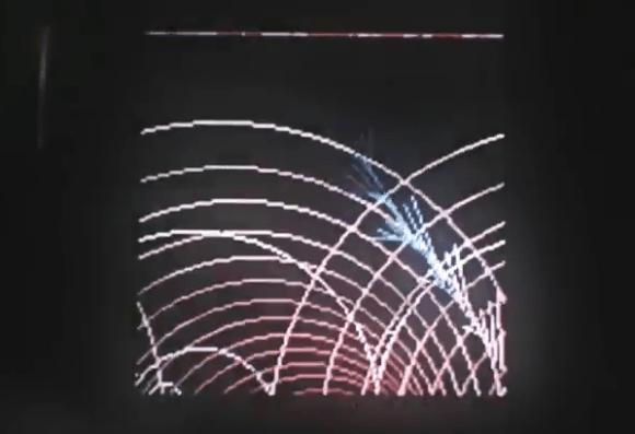
Well that didn’t take long. We just heard last week about the Sony inviting firmware hacks for their SmartWatch and here’s an early example. This image above is an animation running on the watch. It was written as an Arduino sketch which runs on a custom firmware image. [Veqtor] wrote the sketch, which is just a couple of nested loops drawing lines and circles. The real hack is in the firmware itself.

[Veqtor] took part in a workshop (translated) put on by [David Cuartielles] which invited attendees to try their Arduino coding skills on his firmware hack for the watch. It implements an Android parser, but the development is in very early stages. Right now there’s zero information in his readme file. But the root directory of the repo has a huge todo list. Dig through it and see if you can fork his code to help lend a hand.

Learn more about the SmartWatch firmware from the original announcement.


Filed under: Arduino Hacks

I have recently received the following question from a reader: I’m looking for a circuit board design that will need to turn on an array of LEDs when motion is detected during the day time, and also stay on continuously during the night time; using the Arduino would be nice. The project that I am […]

The post Motion and Light Sensors with Arduino (and Without) appeared first on Tinker Hobby.

Nov
08

LED Patterns Using DIP Switch and Arduino

arduino, Beginner, code, DIP switch, sketch, video Comments Off on LED Patterns Using DIP Switch and Arduino 

When I posted the “LED Control Using DIP Switch” sketch last year (a simple setup the turned on the LED corresponding to that switch position), I also had a slightly modified version of it in which the DIP switch controlled six different light patterns on the LEDs (scroll right, left, in, out, back and forth and random). It presented a “cleaned-up” version of the code using for loops and compared it to the “long-hand” version, showing the trade-off between ease of understanding and conciseness. Except that… I forgot to post it.

Last week someone contacted me asking a question about a similar project he is working on and when I wanted to refer him to this modified sketch I realized it wasn’t on the blog. (Here’s the original sketch and schematic for reference).

What follows below is the missing blog post (not anymore), a comparison between the more readable sketch (easier for beginners to understand) and the more concise version, in a series of snippets showing the main differences between the two versions of the sketch.

The concise version generates a binary sketch that occupies approximately 25% less memory and is almost half as long in lines of code. The entire source code listings are at the very bottom of this post.

Note: the line above each snippet reflects the modification that shortened the sketch.

1) not using #define directives for the LED and switch pins on the Arduino in order to use for loops:

    } else {
     // default: off
     digitalWrite(LED1, LOW);
     digitalWrite(LED2, LOW);
     digitalWrite(LED3, LOW);
     digitalWrite(LED4, LOW);
     digitalWrite(LED5, LOW);
     digitalWrite(LED6, LOW);
   }
    } else {
     // default: off
     for (i = 13; i >= 8; i--) {
       digitalWrite(i, LOW);
     }


2) using a state variable array (and consequently a for loop) as opposed to individual state variables:

   s1state = digitalRead(S1);
   s2state = digitalRead(S2);
   s3state = digitalRead(S3);
   s4state = digitalRead(S4);
   s5state = digitalRead(S5);
   s6state = digitalRead(S6);
   for (i = 0, j = 7; i < 6, j >= 2; i++, j--) {
     state[i] = digitalRead(j);
   }


3) if (x) versus if (x == 1) (when x is either 0 or 1, then the (x == 1) expression can be written as simply (x)):

    } else if (s5state == 1) {
     // scroll back and forth
    } else if (state[4]) {
     // scroll back and forth


4) long, repetitive code to randomly turn on or not each LED (for a random duration up to 300 milliseconds) replaced with for loop:

    } else if (s6state == 1) {
     // random
     randomSeed(analogRead(3));
     onoroff = random(0, 2);
     millisecs = random(0, 301);
     digitalWrite(LED1, onoroff);
     delay(millisecs);
     randomSeed(analogRead(3));
     onoroff = random(0, 2);
     millisecs = random(0, 301);
     digitalWrite(LED2, onoroff);
     delay(millisecs);
     randomSeed(analogRead(3));
     onoroff = random(0, 2);
     millisecs = random(0, 301);
     digitalWrite(LED3, onoroff);
     delay(millisecs);
     randomSeed(analogRead(3));
     onoroff = random(0, 2);
     millisecs = random(0, 301);
     digitalWrite(LED4, onoroff);
     delay(millisecs);
     randomSeed(analogRead(3));
     onoroff = random(0, 2);
     millisecs = random(0, 301);
     digitalWrite(LED5, onoroff);
     delay(millisecs);
     randomSeed(analogRead(3));
     onoroff = random(0, 2);
     millisecs = random(0, 301);
     digitalWrite(LED6, onoroff);
     delay(millisecs);
   }
    } else if (state[5]) {
     // random
     for (i = 13; i >= 8; i--) {
       randomSeed(analogRead(i - 8));
       onoroff = random(0, 2);
       millisecs = random(0, 301);
       digitalWrite(i, onoroff);
       delay(millisecs);
     }
   }


Here’s the full long version:

  • Binary sketch size: 3654 bytes
  • Code size was sacrificed in order to improve readability for beginners
  • Sketch length: 205 lines
  // www.TinkerHobby.com
  // Natalia Fargasch Norman
  // LED control via DIP switches

  // Arduino pins used for the LEDs
  #define LED1 13
  #define LED2 12
  #define LED3 11
  #define LED4 10
  #define LED5 9
  #define LED6 8

  // Arduino pins used for the switches
  #define S1 7
  #define S2 6
  #define S3 5
  #define S4 4
  #define S5 3
  #define S6 2

  // State of each switch (0 or 1)
  int s1state;
  int s2state;
  int s3state;
  int s4state;
  int s5state;
  int s6state;

  // Random values for LED state and delay
  long onoroff;
  long millisecs;

  void setup() {
    // pins for LEDs are outputs
    pinMode(LED1, OUTPUT);
    pinMode(LED2, OUTPUT);
    pinMode(LED3, OUTPUT);
    pinMode(LED4, OUTPUT);
    pinMode(LED5, OUTPUT);
    pinMode(LED6, OUTPUT);
    // pins for switches are inputs
    pinMode(S1, INPUT);
    pinMode(S2, INPUT);
    pinMode(S3, INPUT);
    pinMode(S4, INPUT);
    pinMode(S5, INPUT);
    pinMode(S6, INPUT);
  }

  void loop() {
    s1state = digitalRead(S1);
    s2state = digitalRead(S2);
    s3state = digitalRead(S3);
    s4state = digitalRead(S4);
    s5state = digitalRead(S5);
    s6state = digitalRead(S6);
    if (s1state == 1) {
      // scroll right
      digitalWrite(LED1, HIGH);
      delay(250);
      digitalWrite(LED1, LOW);
      digitalWrite(LED2, HIGH);
      delay(250);
      digitalWrite(LED2, LOW);
      digitalWrite(LED3, HIGH);
      delay(250);
      digitalWrite(LED3, LOW);
      digitalWrite(LED4, HIGH);
      delay(250);
      digitalWrite(LED4, LOW);
      digitalWrite(LED5, HIGH);
      delay(250);
      digitalWrite(LED5, LOW);
      digitalWrite(LED6, HIGH);
      delay(250);
      digitalWrite(LED6, LOW);
    } else if (s2state == 1) {
      // scroll left
      digitalWrite(LED6, HIGH);
      delay(250);
      digitalWrite(LED6, LOW);
      digitalWrite(LED5, HIGH);
      delay(250);
      digitalWrite(LED5, LOW);
      digitalWrite(LED4, HIGH);
      delay(250);
      digitalWrite(LED4, LOW);
      digitalWrite(LED3, HIGH);
      delay(250);
      digitalWrite(LED3, LOW);
      digitalWrite(LED2, HIGH);
      delay(250);
      digitalWrite(LED2, LOW);
      digitalWrite(LED1, HIGH);
      delay(250);
      digitalWrite(LED1, LOW);
    } else if (s3state == 1) {
      // scroll in
      digitalWrite(LED1, HIGH);
      digitalWrite(LED6, HIGH);
      delay(250);
      digitalWrite(LED1, LOW);
      digitalWrite(LED6, LOW);
      digitalWrite(LED2, HIGH);
      digitalWrite(LED5, HIGH);
      delay(250);
      digitalWrite(LED2, LOW);
      digitalWrite(LED5, LOW);
      digitalWrite(LED3, HIGH);
      digitalWrite(LED4, HIGH);
      delay(250);
      digitalWrite(LED3, LOW);
      digitalWrite(LED4, LOW);
    } else if (s4state == 1) {
      // scroll out
      digitalWrite(LED3, HIGH);
      digitalWrite(LED4, HIGH);
      delay(250);
      digitalWrite(LED3, LOW);
      digitalWrite(LED4, LOW);
      digitalWrite(LED2, HIGH);
      digitalWrite(LED5, HIGH);
      delay(250);
      digitalWrite(LED2, LOW);
      digitalWrite(LED5, LOW);
      digitalWrite(LED1, HIGH);
      digitalWrite(LED6, HIGH);
      delay(250);
      digitalWrite(LED1, LOW);
      digitalWrite(LED6, LOW);
    } else if (s5state == 1) {
      // scroll back and forth
      digitalWrite(LED1, HIGH);
      delay(250);
      digitalWrite(LED1, LOW);
      digitalWrite(LED2, HIGH);
      delay(250);
      digitalWrite(LED2, LOW);
      digitalWrite(LED3, HIGH);
      delay(250);
      digitalWrite(LED3, LOW);
      digitalWrite(LED4, HIGH);
      delay(250);
      digitalWrite(LED4, LOW);
      digitalWrite(LED5, HIGH);
      delay(250);
      digitalWrite(LED5, LOW);
      digitalWrite(LED6, HIGH);
      delay(250);
      digitalWrite(LED6, LOW);
      digitalWrite(LED5, HIGH);
      delay(250);
      digitalWrite(LED5, LOW);
      digitalWrite(LED4, HIGH);
      delay(250);
      digitalWrite(LED4, LOW);
      digitalWrite(LED3, HIGH);
      delay(250);
      digitalWrite(LED3, LOW);
      digitalWrite(LED2, HIGH);
      delay(250);
      digitalWrite(LED2, LOW);
    } else if (s6state == 1) {
      // random
      randomSeed(analogRead(3));
      onoroff = random(0, 2);
      millisecs = random(0, 301);
      digitalWrite(LED1, onoroff);
      delay(millisecs);
      randomSeed(analogRead(3));
      onoroff = random(0, 2);
      millisecs = random(0, 301);
      digitalWrite(LED2, onoroff);
      delay(millisecs);
      randomSeed(analogRead(3));
      onoroff = random(0, 2);
      millisecs = random(0, 301);
      digitalWrite(LED3, onoroff);
      delay(millisecs);
      randomSeed(analogRead(3));
      onoroff = random(0, 2);
      millisecs = random(0, 301);
      digitalWrite(LED4, onoroff);
      delay(millisecs);
      randomSeed(analogRead(3));
      onoroff = random(0, 2);
      millisecs = random(0, 301);
      digitalWrite(LED5, onoroff);
      delay(millisecs);
      randomSeed(analogRead(3));
      onoroff = random(0, 2);
      millisecs = random(0, 301);
      digitalWrite(LED6, onoroff);
      delay(millisecs);
    } else {
      // default: off
      digitalWrite(LED1, LOW);
      digitalWrite(LED2, LOW);
      digitalWrite(LED3, LOW);
      digitalWrite(LED4, LOW);
      digitalWrite(LED5, LOW);
      digitalWrite(LED6, LOW);
    }
  }


And here’s the full “cleaned-up” version:

  • Binary sketch size: 2826 bytes
  • Sketch length: 119 lines
  // www.TinkerHobby.com
  // Natalia Fargasch Norman
  // LED control via DIP switches

  // Arduino pins used for the LEDs
  // LED1 13
  // LED2 12
  // LED3 11
  // LED4 10
  // LED5 9
  // LED6 8

  // Arduino pins used for the switches
  // S1 7
  // S2 6
  // S3 5
  // S4 4
  // S5 3
  // S6 2

  // State of each switch (0 or 1)
  int state[6];

  // Random values for LED state and delay
  long onoroff;
  long millisecs;

  // loop counters
  int i, j;

  // delay
  int d = 250;

  void setup() {
    // pins for LEDs are outputs
    // LEDs 1-6 on pins 13-8
    for (i = 13; i >= 8; i--) {
      pinMode(i, OUTPUT);
    }
    // pins for switches are inputs
    // switches 1-6 on pins 7-2
    for (i = 7; i >= 2; i--) {
      pinMode(i, INPUT);
    }
  }

  void loop() {
    for (i = 0, j = 7; i < 6, j >= 2; i++, j--) {
      state[i] = digitalRead(j);
    }

    if (state[0]) {
      // scroll right
      for (i = 13; i >= 8; i--) {
        digitalWrite(i, HIGH);
        delay(d);
        digitalWrite(i, LOW);
      }

    } else if (state[1]) {
      // scroll left
      for (i = 8; i <= 13; i++) {
         digitalWrite(i, HIGH);
         delay(d);
         digitalWrite(i, LOW);
       }

   } else if (state[2]) {
       // scroll in
       // light up LEDs on pins i and 8+(13-i)
       for (i = 13; i >= 11; i--) {
        digitalWrite(i, HIGH);
        digitalWrite(21 - i, HIGH);
        delay(d);
        digitalWrite(i, LOW);
        digitalWrite(21 - i, LOW);
      }

    } else if (state[3]) {
      // scroll out
      // light up LEDs on pins i and 8+(13-i)
      for (i = 11; i <= 13; i++) {
         digitalWrite(i, HIGH);
         digitalWrite(21 - i, HIGH);
         delay(d);
         digitalWrite(i, LOW);
         digitalWrite(21 - i, LOW);
       }

    } else if (state[4]) {
       // scroll back and forth
       for (i = 13; i >= 8; i--) {
        digitalWrite(i, HIGH);
        delay(d);
        digitalWrite(i, LOW);
      }
      for (i = 9; i <= 12; i++) {
        digitalWrite(i, HIGH);
        delay(d);
        digitalWrite(i, LOW);
      }

    } else if (state[5]) {
       // random
       for (i = 13; i >= 8; i--) {
        randomSeed(analogRead(i - 8));
        onoroff = random(0, 2);
        millisecs = random(0, 301);
        digitalWrite(i, onoroff);
        delay(millisecs);
      }      

    } else {
      // default: off
      for (i = 13; i >= 8; i--) {
        digitalWrite(i, LOW);
      }
    }
  }

Check out the video of this sketch in action.

LED Patterns Using DIP Switch and Arduino originally appeared on Tinker Hobby on November 8, 2011.

May
31

Arduino Serial Display: Introducing the GLO-216 2×16 Multifont Serial OLED Display

arduino, code, OLED, OLED display, sketch Comments Off on Arduino Serial Display: Introducing the GLO-216 2×16 Multifont Serial OLED Display 

GLO216 Serial OLED DisplayThe GLO-216 2×16 Multifont Serial OLED allows you to translate 9600bps serial data into bright, high-contrast text on a compact screen. This low cost, low power serial display comes in two font colors (yellow and green) and is made and sold by seetron.com, owned by Scott Edwards of Electronics Now and Nuts & Volts fame.

Think of the GLO-216 as a “mini terminal” that displays text and custom characters and responds to control characters such as tabs, linefeeds, carriage returns, backspace, etc. It is compatible with RS-232, Stamps, PICs and Arduino; pretty much any serial out, really.

The display uses less than 50mA, so it can be connected straight to the Arduino‘s power supply.

The GLO-216 can store startup text and custom characters in EEPROM and there are instructions to save and recall this information. The simple sketch created to test the display creates and saves a new heart shaped custom character, then displays it on the screen along with some text.

Seetron.com has set up a special offer for tinkerhobby.com readers: you can save 20% off a GLO-216 if you use promo code “HOBBYIST” upon check out. For more information and to purchase, see the GLO-216 product page.

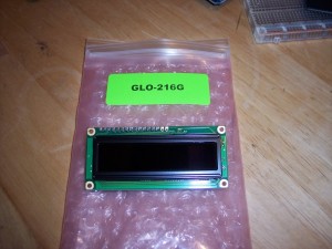
Here’s the GLO-216G just out of the box:
GLO216 OLED display front
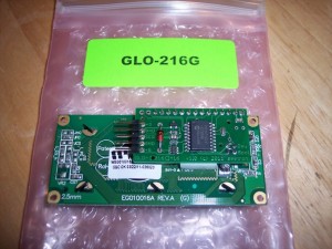
And here’s the view from the back, notice the small board that brings out the pins nicely to a 5-pin header and saves you some soldering work:
GLO216 OLED display back
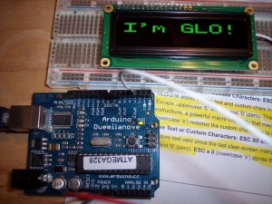
This is what it looks like when you first power it on:
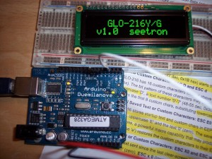
GLO216 Serial OLED Display by seetron
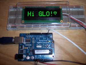
And here’s the result of running the sketch I included in this post, that defines and prints a custom character:
GLO216 Serial OLED Display custom character

The sketch to drive the display uses the “newsoftserial” library, which can be found here: http://arduiniana.org/libraries/newsoftserial

A few nice features of the newsoftserial library compared to the original softserial are more accurate timing, smaller code size, but best of all the ability to output “inverted” serial (the Arduino documentation states that their serial output is not RS-232 compatible, but newsoftserial permits the Arduino to output inverted serial).

Sketch:

// Test of the GLO-216G serial OLED display
// Natalia Fargasch Norman @ tinkerhobby.com

// GLO-216Y/G information: http://www.seetron.com/glo216.html
// Programming reference: http://seetron.com/glo216/glo216prog.html

#include <SoftwareSerial.h>
#include <GLO216.h>

#define rxPin 255
#define txPin 3
#define NULL 0x00

int inverted = 1;

SoftwareSerial mySerial = SoftwareSerial(rxPin, txPin, inverted);

void setup() {
  pinMode(txPin, OUTPUT);
  digitalWrite(txPin, LOW);
  mySerial.begin(9600);
  delay(10);

  // clears the screen and select font size and style
  char instr1[] = {
    clearScreen(),
    defaultSize(),
    selectSize(), // tall
    selectSize(), // wide
    selectSize(), // big
    textStyle(),
    NULL
  };
  const char message[] = "Hi GLO!";
  mySerial.print(instr1);
  // print message according to prior instructions
  mySerial.print(message);

  // defines a new custom heart shaped character
  char instr2[] = {
    // escape sequence to receive new custom character
    escape(),'D','0',
    // heart pattern using tool at http://seetron.com/apps/app_cceditor.html
    0x80,0x8A,0x95,0x91,0x8A,0x84,0x80,0x80,
    NULL
  };
  // print character 0x80, the newly defined heart
  const char msg[] = {0x80, NULL};
  mySerial.print(instr2);
  // print message according to prior instructions
  mySerial.print(msg);

/*  delay(3000);

  char instr3[] = {
    clearScreen(),
    NULL
  };
  mySerial.print(instr3);*/
}

void loop() {
  // ...
}

GLO216 functions:

// GLO-216G serial OLED display
// Natalia Fargasch Norman @ tinkerhobby.com

// GLO-216Y/G information: http://www.seetron.com/glo216.html
// Programming reference: http://seetron.com/glo216/glo216prog.html

/*
Parameters for setPosition and rightAlign instructions:
setPosition: position + 0x40
rightAlign: '0'-'7'
*/

/*
Parameters for escape instructions:
Define lower custom character: 'D', '0'-'7'
Define upper custom character: 'd', '0'-'7'
Recall saved text: 'E', '0'
Restore custom character set: 'e', '0'
Save text since last clearScreen: 'X', '0'
Store custom character set: 'x', '0'
*/

// Moves printing position to the first character of top line
char homeCursor() {
  return 0x01;
}

// Cycles the font size: normal -> tall -> wide -> big -> normal -> ...
char selectSize() {
  return 0x02;
}

// Sets font size to default of small on two lines of 16 characters
char defaultSize() {
  return 0x03;
}

// Behaves like the backspace key
char backspace() {
  return 0x08;
}

// Moves printing position to the next multiple of 4 location
char tab() {
  return 0x09;
}

// Moves the printing position down a line
char linefeed() {
  return 0x0A;
}

// Moves the printing position up a line
char verticalTab() {
  return 0x0B;
}

// Clears the screen and moves printing position to 0
char clearScreen() {
  return 0x0C;
}

// Moves to the first printing position of the next line
char carriageReturn() {
  return 0x0D;
}

// Turns on the OLED driver circuitry when it has been previously turned off
char turnOn() {
  return 0x0E;
}

// Turns off the OLED driver circuitry to save power
char turnOff() {
  return 0x0F;
}

// Sets the printing position according to value of next byte
char setPosition() {
  return 0x10;
}

// Prints text at the righthand end of a field of defined size from 2-8
char rightAlign() {
  return 0x12;
}

// Sets seven segment style font for large characters
char sevenSeg() {
  return 0x13;
}

// Sets text style font for large characters
char textStyle() {
  return 0x14;
}

// Begin multi-part instruction
char escape() {
  return 0x1B;
}

// See http://seetron.com/glo216/bpigloupgg.html
char bpkInstr() {
  return 0xFE;
}

Header file:

// GLO-216G serial OLED display
// Natalia Fargasch Norman @ tinkerhobby.com

// GLO-216Y/G information: http://www.seetron.com/glo216.html
// Programming reference: http://seetron.com/glo216/glo216prog.html

#ifndef GLO216_h
#define GLO216_h

// Moves printing position to the first character of top line
char homeCursor();

// Cycles the font size: normal -> tall -> wide -> big -> normal -> ...
char selectSize();

// Sets font size to default of small on two lines of 16 characters
char defaultSize();

// Behaves like the backspace key
char backspace();

// Moves printing position to the next multiple of 4 location
char tab();

// Moves the printing position down a line
char linefeed();

// Moves the printing position up a line
char verticalTab();

// Clears the screen and moves printing position to 0
char clearScreen();

// Moves to the first printing position of the next line
char carriageReturn();

// Turns on the OLED driver circuitry when it has been previously turned off
char turnOn();

// Turns off the OLED driver circuitry to save power
char turnOff();

// Sets the printing position according to value of next byte
char setPosition();

// Prints text at the righthand end of a field of defined size from 2-8
char rightAlign();

// Sets seven segment style font for large characters
char sevenSeg();

// Sets text style font for large characters
char textStyle();

// Begin multi-part instruction
char escape();

// See http://seetron.com/glo216/bpigloupgg.html
char bpkInstr();

#endif

Keywords file:

#######################################
# Syntax Coloring Map for GLO216
#######################################

#######################################
# Datatypes (KEYWORD1)
#######################################

GLO216	KEYWORD1

#######################################
# Methods and Functions (KEYWORD2)
#######################################

homeCursor	KEYWORD2
selectSize	KEYWORD2
defaultSize	KEYWORD2
backspace	KEYWORD2
tab	KEYWORD2
linefeed	KEYWORD2
verticalTab	KEYWORD2
clearScreen	KEYWORD2
carriageReturn	KEYWORD2
turnOn	KEYWORD2
turnOff	KEYWORD2
setPosition	KEYWORD2
rightAlign	KEYWORD2
sevenSeg	KEYWORD2
textStyle	KEYWORD2
escape	KEYWORD2
bpkInstr	KEYWORD2

#######################################
# Constants (LITERAL1)
#######################################

Download these four files in an archive here: GLO216.zip

Arduino Serial Display: Introducing the GLO-216 2×16 Multifont Serial OLED Display originally appeared on Tinker Hobby on May 31, 2011.

Jul
27

Arduino RGB LED Control for the Spinning Night Light | Part 4

arduino, light, Ohm's law, project, resistor, RGB LED, sketch, spinning night light Comments Off on Arduino RGB LED Control for the Spinning Night Light | Part 4 

When looking at the parts list for the Arduino RGB LED spinning night light you must have noticed that current limiting resistors of different values were used for the Red and the Green/Blue pins of the RGB LED. That is due to them having different forward voltage ratings. You can find complete specs for the LED in the datasheet (when buying an electronic component you will have the option to download its datasheet, or the relevant information will be provided by the vendor).

We use Ohm’s Law to calculate current limiting resistor values:

Forward voltage ratings:

RED: 2.1V
GREEN: 3.3V
BLUE: 3.3V

Current:

I = 20mA

Supply voltage:

V = 5V

Ohm’s Law:

I = V/R => R = V/I

So for Red:

(5 – 2.1)/0.02 => R = 145 Ohm

For Green/Blue:

(5 – 3.3)/0.02 => R = 85 Ohm

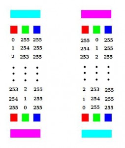
color fading for the RGB LED night lightAs for the Arduino sketch, I chose to have the lamp fade between two colors, aqua (#00FFFF) and magenta (#FF00FF). For that I kept the Blue value at 255 and varied the Green and Red values between 0-255 to achieve the desired colors, as shown in the diagram:
(You can pick your favorite colors, cycle through the entire spectrum, or go psychedelic and show random colors with random delays)

// fade from aqua to magenta
  for (int i = 0; i < 256; i++) {
    analogWrite(RED, 255-i);
    analogWrite(GREEN, i);
    analogWrite(BLUE, 0);
    delay(50);
  }

  // fade from magenta to aqua
  for (int i = 0; i < 256; i++) {
    analogWrite(RED, i);
    analogWrite(GREEN, 255-i);
    analogWrite(BLUE, 0);
    delay(50);
  }

Here’s the full sketch for the night light.

Arduino RGB LED Control for the Spinning Night Light | Part 4 originally appeared on Tinker Hobby on July 27, 2010.


  • Newsletter

    Sign up for the PlanetArduino Newsletter, which delivers the most popular articles via e-mail to your inbox every week. Just fill in the information below and submit.

  • Like Us on Facebook