Posts | Comments

Planet Arduino

Archive for the ‘pins’ Category

There are two kinds of people in the world (and, no, this isn’t a binary joke). People who love the Arduino, and people who hate it. If you’ve ever tried to use a standard prototype board to mount on an Arduino, you’ll know what kind of person you are. When you notice the pins aren’t on 0.1 inch centers, you might think, “What the heck were those idiots thinking!” Or, you might say, “How clever! This way the connectors are keyed to prevent mistakes.” From your choice of statement, we can deduce your feelings on the subject.

[Rssalnero] clearly said something different. We weren’t there, but we suspect it was: “Gee. I should 3D print a jig to bend headers to fit.” Actually, he apparently tried to do it by hand (we’ve tried it, too). The results are not usually very good.

He created two simple 3D printed jigs that let you bend an 8-pin header. The first jig bends the correct offset and the second helps you straighten out the ends again. You can see the result in the picture above.

[Rssalnero] notes that the second jig needed reinforcement, so it is made to take 8 pins to use as fulcrums. Probably doesn’t hurt to print the jigs fairly solid and using harder plastic like ABS or PETG, too. Even if you don’t have a 3D printer, this is about a 15 or 30 minute print on any sort of reasonable printer, so make a friend. Worst case, you could have one of the 3D printing vendors make it for you, or buy local.

We love little tool hacks like this. If you are too lazy to snap 8 pins off a 40 pin strip, maybe you’d like some help. If you’d rather go with a custom PC board, you might start here.


Filed under: Arduino Hacks, tool hacks
Dec
10

Discover Arduino Xmas Pack, free shipping for US and EU!

arduino, Featured, pins, StarterKit, Xmas Pack Comments Off on Discover Arduino Xmas Pack, free shipping for US and EU! 

XmasPack

This holiday season we have a special package for you. Arduino Xmas Pack contains all you need to make the perfect gift for anybody willing to get into the Arduino world and put their hands on official gadgets and the widely appreciated Arduino Starter Kit.

The Starter Kit walks you through the basics of Arduino and electronics in a hands-on way through 15 projects to build, hack and share something great every day.

Xmas Pack includes (see pic above):

  • Arduino Starter Kit in Italian or English
  • Arduino T-Shirt (you can choose your size)
  • Arduino Mug
  • 6 Pins

Arduino Xmas Pack is sold only on the Arduino Store at 100€/124 $ and ships for FREE in US and Europe.

If you want to be sure to receive it for Christmas, check the timing to place orders on this page.

Make it yours for Christmas >> English edition or Italian Edition


Sep
14

Arduino LED Control Using DIP Switch | Part 1

arduino, Beginner, DIP switch, LED, pins, project, serial communication Comments Off on Arduino LED Control Using DIP Switch | Part 1 

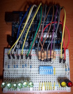
LED control using DIP switchThis is a very simple project that controls a set of LEDs using a DIP switch. The purpose of the sketch is to show the use of some Arduino serial communication functions, and to increase familiarity interfacing with digital I/O pins.

Two LEDs were connected to the RX and TX pins on the Arduino (digital pins 0 and 1), but remember to disconnect these pins while the sketch is being uploaded.

Parts list:

Sketch:

// www.TinkerHobby.com
// Natalia Fargasch Norman
// LED control via DIP switches

// Arduino pins used for the LEDs
#define LED1 13
#define LED2 12
#define LED3 11
#define LED4 10
#define LED5 9
#define LED6 8

// Arduino pins used for the switches
#define S1 7
#define S2 6
#define S3 5
#define S4 4
#define S5 3
#define S6 2

// State of each switch (0 or 1)
int s1state;
int s2state;
int s3state;
int s4state;
int s5state;
int s6state;

void setup() {
  // pins for LEDs are outputs
  pinMode(LED1, OUTPUT);
  pinMode(LED2, OUTPUT);
  pinMode(LED3, OUTPUT);
  pinMode(LED4, OUTPUT);
  pinMode(LED5, OUTPUT);
  pinMode(LED6, OUTPUT);
  // pins for switches are inputs
  pinMode(S1, INPUT);
  pinMode(S2, INPUT);
  pinMode(S3, INPUT);
  pinMode(S4, INPUT);
  pinMode(S5, INPUT);
  pinMode(S6, INPUT);
  // setup serial port
  Serial.begin(9600);
  Serial.println("Serial port open");
}

void loop() {
  s1state = digitalRead(S1);
  digitalWrite(LED1, s1state);
  s2state = digitalRead(S2);
  digitalWrite(LED2, s2state);
  s3state = digitalRead(S3);
  digitalWrite(LED3, s3state);
  s4state = digitalRead(S4);
  digitalWrite(LED4, s4state);
  s5state = digitalRead(S5);
  digitalWrite(LED5, s5state);
  s6state = digitalRead(S6);
  digitalWrite(LED6, s6state);
  Serial.print(s1state);
  Serial.print(s2state);
  Serial.print(s3state);
  Serial.print(s4state);
  Serial.print(s5state);
  Serial.print(s6state);
  Serial.println();
}

Here is the schematic for this project.

Here’s a video of the project in action.

Arduino LED Control Using DIP Switch | Part 1 originally appeared on Tinker Hobby on September 14, 2010.


  • Newsletter

    Sign up for the PlanetArduino Newsletter, which delivers the most popular articles via e-mail to your inbox every week. Just fill in the information below and submit.

  • Like Us on Facebook