
12
I wanted to learn how to design physical objects in 3D mechanical CAD, so I started to learn Autodesk Fusion 360. It’s free for “students, enthusiasts, hobbyists, and startups”, but cloud based and closed source, so it could be vastly more limited since this blog post was written in November 2016. It might be a better idea to try to learn (and maybe contribute to) one of the open source mechanical CAD packages like FreeCAD, but a good friend of mine had good luck with Fusion 360 so I went with that.
To start with, I’ve never used a parametric 3D modeler before, so I am probably doing everything wrong. Here are some of the tutorials I followed:
- Get started with Fusion 360 – 12 tutorials in under 60 minutes
- Fusion 360 Tutorials (with actually-useful video/screencasts)
I wanted to design something simple as my first project in Fusion 360. We do a reasonable amount of laser cutting at W&L, and I’ve noticed that the work-pieces sometimes get little scorch marks where the laser hits the aluminum hexagonal support structure underneath. Our most common piece of stock is 12x12x1/3 inch baltic birch plywood, and I though it might be cool to design and 3D print some simple pieces to support the wood from the corners, to avoid scorch marks and to allow the little cutout pieces to fall through. I had envisioned an L-shaped piece with a ledge for the wood to sit. Maybe with a hole in the corner in case we want to add a screw to hold the wood to the support (if gravity isn’t enough).
If you want to follow-along in Fusion 360, here is a link to the design, where you can download it in Fusion 360 format, STL, or any other of a large number of formats.
As far as I have learned, this kind of 3D CAD tool is organized as a sequence of sketches (where you draw points and lines in a 2D plane) and “actions” (probably the wrong word) such as extrude and fillet. Parametric modelers are cool because you can define parameters, then use those parameters to adjust dimensions in your sketch. This makes it easy for your designs to be flexible, where you can define a “bolt diameter” parameter and adjust if you need to change to metric hardware (for example).
For this simple design I had three sketches, three cuts/extrusions, and one unnecessary and flamboyant fillet  . I’ll go through each step in this blog post. Again, this is probably a non-optimal way to do this kind of thing.
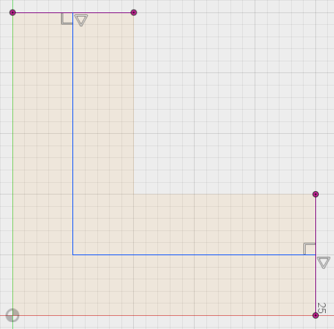
Sketch 1: The bottom of the thing

Another cool thing about this kind of parametric modeler is that you can specify all sorts of constraints in the sketch, and it will adjust the sketch based on changing parameters. For example, you can add a right-angle constraint between two lines. If you then rotate one of the lines, the system will do its best to keep the lines at a right angle. In the sketch above, you can see some right-angle constraints and a vertical constraint. The overall dimensions are 25 x 25 mm.
Extrude 1
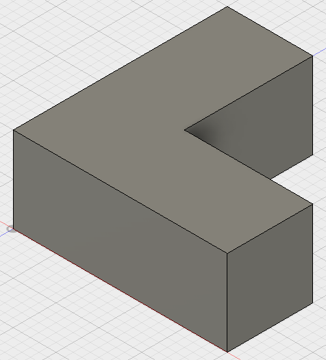
I extruded the L-shaped Sketch upward in the vertical direction by 10 mm.
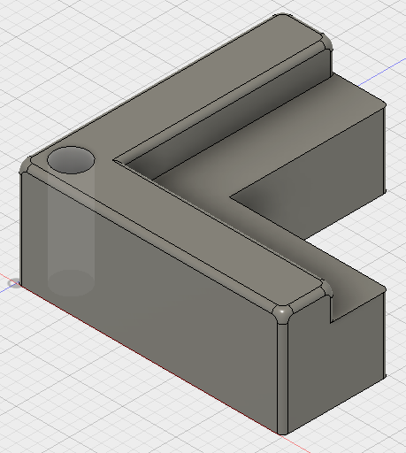
Sketch 2: Building a shelf area
Here I added lines down the middle of each “arm” of the L-shape. This way I can extrude part back down to the create a little shelf for the wood.
Extrude 2
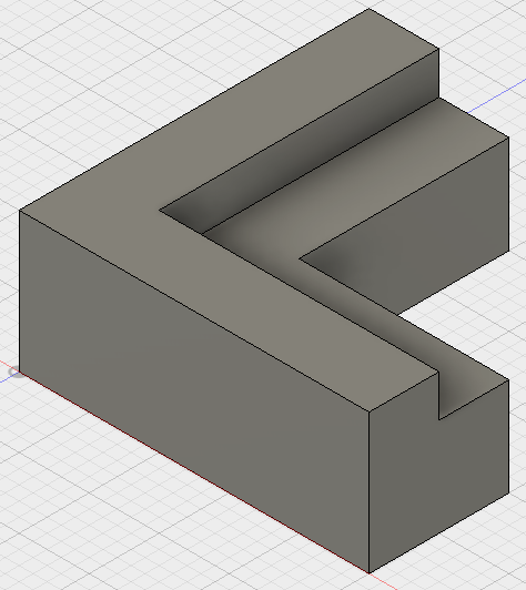
I did an extrude (technically a cut) downward to create the little shelf.
Fillet
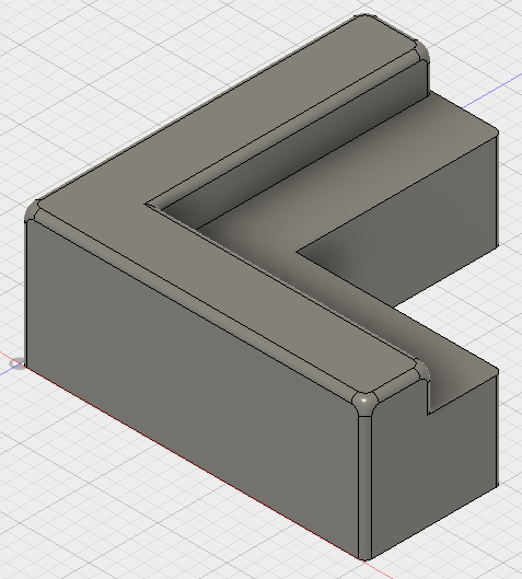
A fillet is “a rounding of an interior or exterior corner of a part design” (from Wikipedia), added to help reduce drag, improve mechanical strength, and just make the part look fancy and professional! Here I added a fillet with 0.5 mm radius. I did not apply the fillet to the bottom or the support surface under the wood.
Sketch 3: Adding a hole just in case
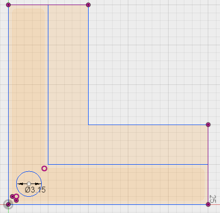
I thought maybe we might want to add a screw in the corner to help hold down the work-piece. Easy enough to add at this stage.
Extrude 3
The hole is cut/extruded through the whole piece.
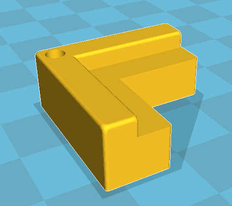
3D Printing
Using the Make –> 3D Print menu we can export an STL file suitable for 3D printing.
Results
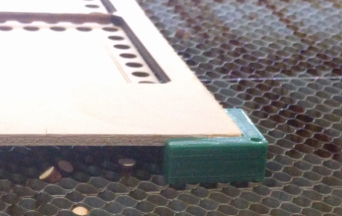
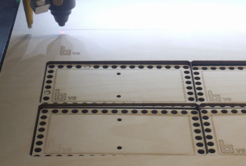
The four corner holders work quite well for elevating the work-piece above the cutting bed. The small pieces fall through and don’t interfere with the cutting head. The larger pieces don’t get any scorch marks when they are cut out.
Conclusion
Overall, this was a fun thing to design and a decent way to gain experience with Fusion 360 for 3D modeling. Next time I might make the support taller than 10 mm to give more clearance for falling parts.

