Posts | Comments

Planet Arduino

Archive for the ‘PMDway’ Category

Now and again you may find yourself needing to use more than one device with the same I2C bus address with your Arduino.

Such as four OLEDs for a large display – or seven temperature sensors that are wired across a chicken hatchling coop.

These types of problems can be solved with the TCA9548A 1-to-8 I2C Multiplexer Breakout, and in this guide we’ll run through the how to make it happen with some example devices.

Getting Started

First, consider the TCA9548A itself. It is the gateway between your Arduino and eight separate I2C buses. You have a single bus on one side, connected to your Arduino.

On the other side of the TCA9548A, you have eight I2C buses, and only one of these can be connected to the Arduino at a time. For example (from the data sheet):

TCA9548A 1-to-8 I2C Multiplexer Breakout from PMD Way with free delivery worldwide

The TCA9548 can operate on voltages between 1.8 and 5V DC… and operate with devices that have operating voltages between 1.8 and 5V DC. This is very convenient, as (for example) you can use devices made for 3.3V operation with 5V Arduinos, or vice versa. Awesome. So let’s get started.

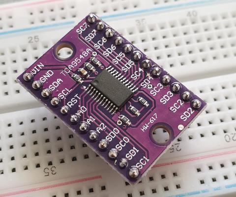
The breakout board includes inline header pins, which are not soldered to the board. So you need to do that. An easy way to line up the pins properly is to drop them into a soldereless breadboard, as such:

TCA9548A 1-to-8 I2C Multiplexer Breakout from PMD Way with free delivery worldwide

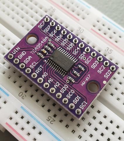
Then after a moment or two of soldering, you’re ready to use:

tca9548a_breadboard_ready_large

Next, insert your module into a solderless breadboard and wire it up as shown:

tca9548a_breadboard_ready_2_large

We are using the red and blue vertical strips on the breadboard as 5V and GND respectively. Finally, we connect the 5V and GND from the Arduino to the solderless breadboard, and A4/A5 to SDA/SCL respectively on the breakout board:

tca9548a_breadboard_ready_3_large

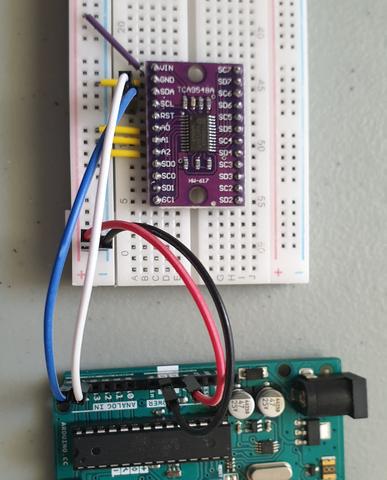
The electrical connections are as follows (Module — Arduino):

  • Vin to 5V
  • GND to GND
  • A0 to GND
  • A1 to GND
  • A2 to GND
  • SDA to A4
  • SCL to A5

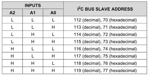
Next, we consider the I2C bus address for the TCA9548A. Using the wiring setup shown above, the address is set to 0x70. You only need to change this if one of your other devices also has an address of 0x70, as shown in the next step.

Changing the I2C address of the TCA9548A

The bus address of the TCA9548A is changed using the connections to the A0, A1 and A2 pins. By default in the tutorial we use 0x70, by wiring A0~A2 to GND (known as LOW). Using the table below, you can reconfigure to an address between 0x70 and 0x77 by matching the inputs to HIGH (5V) or LOW (GND):

tca9548a_address_table_large

Testing 

Before we get too excited, now is a good time to test our wiring to ensure the Arduino can communicate with the TCA9548A. We’ll do this by running an I2C scanner sketch, which returns the bus address of a connected device.

Copy and paste this sketch into your Arduino IDE and upload it to your board. Then, open the serial monitor and set the data rate to 115200. You should be presented with something like the following:

TCA9548A 1-to-8 I2C Multiplexer Breakout from PMD Way with free delivery worldwide

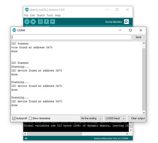
As you can see, our scanner returned an address of 0x70, which matches the wiring described in the bus address table mentioned earlier. If you did not find success, unplug the Arduino from the computer and double-check your wiring – then try again.

Controlling the bus selector

Using the TCA9548A is your sketch is not complex at all, it only requires one step before using your I2C device as normal. That extra step is to instruct the TCA9548A to use one of the eight buses that it controls.

To do this, we send a byte of data to the TCA9548A’s bus register which represents which of the eight buses we want to use. Each bit of the byte is used to turn the bus on or off, with the MSB (most significant bit) for bus 7, and the LSB (least significant bit) for bus 0.

For example, if you sent:

0b00000001 (in binary) or 0 in decimal

… this would activate bus zero.

Or if you sent:

0b00010000 (in binary)

… this would activate bus five.

Once you select a bus, the TCA9548A channels all data in and out of the bus to the Arduino on the selected bus. You only need to send the bus selection data when you want to change buses. We’ll demonstrate that later.

So to make life easier, we can use a little function to easily select the required bus:

void TCA9548A(uint8_t bus)
{
  Wire.beginTransmission(0x70);  // TCA9548A address is 0x70
  Wire.write(1 << bus);          // send byte to select bus
  Wire.endTransmission();
}

This function accepts a bus number and places a “1” in the TCA9548A’s bus register matching our requirements. Then, you simply slip this function right before needing to access a device on a particular I2C bus. For example, a device on bus 0:

TCA9548A(0);

… or a device on bus 6:

TCA9548A(6);

A quick note about pull-up resistors

You still need to use pull-up resistors on the eight I2C buses eminating from the TCA9548A. If you’re using an assembled module, such as our example devices – they will have the resistors – so don’t panic.

If not, check the data sheets for your devices to determine the appropriate pull-up resistors value. If this information isn’t available, try 10k0 resistors.

Controlling our first device

Our first example device is the tiny 0.49″ OLED display. It is has four connections, which are wired as follows (OLED — TCA9548A/Arduino):

  • GND to GND
  • Vcc to Arduino 3.3V
  • CL to TCA9548A SC0 (bus #0, clock pin)
  • DA to TCA9548A SD1 (bus #0, data pin)

The OLED runs from 3.3V, so that’s why we’re powering it directly from the Arduino’s 3.3V pin.

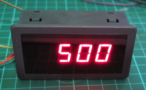
Now, copy and upload this sketch to your Arduino, and after a moment the OLED will display some numbers counting down in various amounts:

So how did that work? We inserted out bus selection function at line 9 of the sketch, then called the function in at line 26 to tell the TCA9548A that we wanted to use I2C bus zero. Then the rest of the sketch used the OLED as normal.

Controlling two devices

Let’s add another device, a BMP180 barometric pressure sensor module. We’ll connect this to I2C bus number seven on the TCA5948A. There are four connections, which are wired as follows (BMP180 — TCA9548A/Arduino):

  • GND to GND
  • Vcc to Arduino 3.3V
  • CL to TCA9548A SC0 (bus #7, clock pin)
  • DA to TCA9548A SD1 (bus #7, data pin)

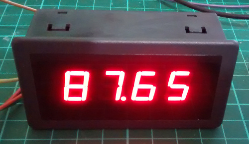
Now, copy and upload this sketch to the Arduino, and after a moment the OLED will display the ambient temperature from the BMP180 in whole degrees Celsius. This is demonstrated in the following video (finger is placed on the BMP180 for force a rise in temperature):

So how did that work? We set up the libraries and required code for the OLED, BMP180 and TCA5948A as usual.

We need to intialise the BMP180, so this is done at line 29 – where we select the I2C bus 7 before initiating the BMP180.

The the sketch operates. On line 40 we again request I2C bus 7 from the TCA9548A, then get the temperature from the BMP180.

On line 44 we request I2C bus 0 from the TCA9548A, and then display the temperature on the OLED. Then repeat.

A quick note about the reset pin

More advanced users will be happy to know they can reset the TCA9548A status, to recover from a bus-fault condition. To do this, simply drop the RESET pin LOW (that is, connect it to GND).

Where to from here? 

You can now understand through our worked example how easy it is to use the TCA9548A and access eight secondary I2C buses through the one bus from your Arduino. Don’t forget that the TCA9548A also does double-duty as a level converter, thereby increasing its value to you.

And that’s all for now. This post brought to you by pmdway.com – everything for makers and electronics enthusiasts, with free delivery worldwide.

To keep up to date with new posts at tronixstuff.com, please subscribe to the mailing list in the box on the right, or follow us on twitter @tronixstuff.

The purpose of this guide is to get your 0.96″ color LCD display successfully operating with your Arduino, so you can move forward and experiment and explore further types of operation with the display. This includes installing the Arduino library, making a succesful board connection and running a demonstration sketch.

Although you can use the display with an Arduino Uno or other boad with an ATmega328-series microcontroller – this isn’t recommended for especially large projects. The library eats up a fair amount of flash memory – around 60% in most cases.

So if you’re running larger projects we recommend using an Arduino Mega or Due-compatible board due to the increased amount of flash memory in their host microcontrollers.

Installing the Arduino library

So let’s get started. We’ll first install the Arduino library then move on to hardware connection and then operating the display.

(As the display uses the ST7735S controller IC, you may be tempted to use the default TFT library included with the Arduino IDE – however it isn’t that reliable. Instead, please follow the instructions below). 

First – download the special Arduino library for your display and save it into your Downloads or a temp folder.

Next – open the Arduino IDE and select the Sketch > Include Library > Add .ZIP library option as shown below:

libraryinstall

A dialog box will open – navigate to and select the zip file you downloaded earlier. After a moment or two the IDE will then install the library.

Please check that the library has been installed – to do this, select the Sketch > Include Library option in the IDE and scroll down the long menu until you see “ER-TFTM0.96-1” as shown below:

libraryinstalled

Once that has been successful, you can wire up your display.

Connecting the display to your Arduino

The display uses the SPI data bus for communication, and is a 3.3V board. You can use it with an Arduino or other 5V board as the logic is tolerant of higher voltages.

Arduino to Display

GND ----- GND (GND)
3.3V ---- Vcc (3.3V power supply)
D13 ----- SCL (SPI bus clock)
D11 ----- SDA (SPI bus data out from Arduino)
D10 ----- CS (SPI bus "Chip Select")
D9 ------ DC (Data instruction select pin)
D8 ------ RES (reset input)

If your Arduino has different pinouts than the Uno, locate the SPI pins for your board and modify as appropriate.

Demonstration sketch

Open a new sketch in the IDE, then copy and paste the following sketch into the IDE:

// https://pmdway.com/products/0-96-80-x-160-full-color-lcd-module
#include <UTFT.h>

// Declare which fonts we will be using
extern uint8_t SmallFont[];

// Initialize display
// Library only supports software SPI at this time
//NOTE: support  DUE , MEGA , UNO 
//SDI=11  SCL=13  /CS =10  /RST=8  D/C=9
UTFT myGLCD(ST7735S_4L_80160,11,13,10,8,9);    //LCD:  4Line  serial interface      SDI  SCL  /CS  /RST  D/C    NOTE:Only support  DUE   MEGA  UNO

// Declare which fonts we will be using
extern uint8_t BigFont[];

int color = 0;
word colorlist[] = {VGA_WHITE, VGA_BLACK, VGA_RED, VGA_BLUE, VGA_GREEN, VGA_FUCHSIA, VGA_YELLOW, VGA_AQUA};
int  bsize = 4;

void drawColorMarkerAndBrushSize(int col)
{
  myGLCD.setColor(VGA_BLACK);
  myGLCD.fillRect(25, 0, 31, 239);
  myGLCD.fillRect(myGLCD.getDisplayXSize()-31, 161, myGLCD.getDisplayXSize()-1, 191);
  myGLCD.setColor(VGA_WHITE);
  myGLCD.drawPixel(25, (col*30)+15);
  for (int i=1; i<7; i++)
    myGLCD.drawLine(25+i, ((col*30)+15)-i, 25+i, ((col*30)+15)+i);
  
  if (color==1)
    myGLCD.setColor(VGA_WHITE);
  else
    myGLCD.setColor(colorlist[col]);
  if (bsize==1)
    myGLCD.drawPixel(myGLCD.getDisplayXSize()-15, 177);
  else
    myGLCD.fillCircle(myGLCD.getDisplayXSize()-15, 177, bsize);
    
  myGLCD.setColor(colorlist[col]);
}
void setup()
{
  randomSeed(analogRead(0));
  
// Setup the LCD
  myGLCD.InitLCD();
  myGLCD.setFont(SmallFont);
}

void loop()
{
  int buf[158];
  int x, x2;
  int y, y2;
  int r;

// Clear the screen and draw the frame
  myGLCD.clrScr();

  myGLCD.setColor(255, 0, 0);
  myGLCD.fillRect(0, 0, 159, 13);
  myGLCD.setColor(64, 64, 64);
  myGLCD.fillRect(0, 114, 159, 127);
  myGLCD.setColor(255, 255, 255);
  myGLCD.setBackColor(255, 0, 0);
  myGLCD.print("pmdway.com.", CENTER, 1);
  myGLCD.setBackColor(64, 64, 64);
  myGLCD.setColor(255,255,0);
  myGLCD.print("pmdway.com", LEFT, 114);


  myGLCD.setColor(0, 0, 255);
  myGLCD.drawRect(0, 13, 159, 113);

// Draw crosshairs
  myGLCD.setColor(0, 0, 255);
  myGLCD.setBackColor(0, 0, 0);
  myGLCD.drawLine(79, 14, 79, 113);
  myGLCD.drawLine(1, 63, 158, 63);
  
 myGLCD.setColor(0, 0, 255);
 myGLCD.drawLine(0, 79, 159, 79);
 
  for (int i=9; i<150; i+=10)
    myGLCD.drawLine(i, 61, i, 65);
  for (int i=19; i<110; i+=10)
    myGLCD.drawLine(77, i, 81, i);
    

// Draw sin-, cos- and tan-lines  
  myGLCD.setColor(0,255,255);
  myGLCD.print("Sin", 5, 15);
  for (int i=1; i<158; i++)
  {
    myGLCD.drawPixel(i,63+(sin(((i*2.27)*3.14)/180)*40));
  }
  
  myGLCD.setColor(255,0,0);
  myGLCD.print("Cos", 5, 27);
  for (int i=1; i<158; i++)
  {
    myGLCD.drawPixel(i,63+(cos(((i*2.27)*3.14)/180)*40));
  }

  myGLCD.setColor(255,255,0);
  myGLCD.print("Tan", 5, 39);
  for (int i=1; i<158; i++)
  {
    myGLCD.drawPixel(i,63+(tan(((i*2.27)*3.14)/180)));
  }

  delay(2000);

  myGLCD.setColor(0,0,0);
  myGLCD.fillRect(1,14,158,113);
  myGLCD.setColor(0, 0, 255);
  myGLCD.setBackColor(0, 0, 0);
  myGLCD.drawLine(79, 14, 79, 113);
  myGLCD.drawLine(1, 63, 158, 63);

 myGLCD.setColor(0, 0, 255);
 myGLCD.drawLine(0, 79, 159, 79);  

// Draw a moving sinewave
  x=1;
  for (int i=1; i<(158*20); i++) 
  {
    x++;
    if (x==159)
      x=1;
    if (i>159)
    {
      if ((x==79)||(buf[x-1]==63))
        myGLCD.setColor(0,0,255);
      else
        myGLCD.setColor(0,0,0);
      myGLCD.drawPixel(x,buf[x-1]);
    }
    myGLCD.setColor(0,255,255);
    y=63+(sin(((i*2.5)*3.14)/180)*(40-(i / 100)));
    myGLCD.drawPixel(x,y);
    buf[x-1]=y;
  }

  delay(2000);
 
  myGLCD.setColor(0,0,0);
  myGLCD.fillRect(1,14,158,113);
  
 myGLCD.setColor(0, 0, 255);
 myGLCD.drawLine(0, 79, 159, 79);  

// Draw some filled rectangles
  for (int i=1; i<6; i++)
  {
    switch (i)
    {
      case 1:
        myGLCD.setColor(255,0,255);
        break;
      case 2:
        myGLCD.setColor(255,0,0);
        break;
      case 3:
        myGLCD.setColor(0,255,0);
        break;
      case 4:
        myGLCD.setColor(0,0,255);
        break;
      case 5:
        myGLCD.setColor(255,255,0);
        break;
    }
    myGLCD.fillRect(39+(i*10), 23+(i*10), 59+(i*10), 43+(i*10));
  }

  delay(2000);
  
  myGLCD.setColor(0,0,0);
  myGLCD.fillRect(1,14,158,113);
  myGLCD.setColor(0, 0, 255);
 myGLCD.drawLine(0, 79, 159, 79);   

// Draw some filled, rounded rectangles
  for (int i=1; i<6; i++)
  {
    switch (i)
    {
      case 1:
        myGLCD.setColor(255,0,255);
        break;
      case 2:
        myGLCD.setColor(255,0,0);
        break;
      case 3:
        myGLCD.setColor(0,255,0);
        break;
      case 4:
        myGLCD.setColor(0,0,255);
        break;
      case 5:
        myGLCD.setColor(255,255,0);
        break;
    }
    myGLCD.fillRoundRect(99-(i*10), 23+(i*10), 119-(i*10), 43+(i*10));
  }

  delay(2000);
  
  myGLCD.setColor(0,0,0);
  myGLCD.fillRect(1,14,158,113);

 myGLCD.setColor(0, 0, 255);
 myGLCD.drawLine(0, 79, 159, 79);  
// Draw some filled circles
  for (int i=1; i<6; i++)
  {
    switch (i)
    {
      case 1:
        myGLCD.setColor(255,0,255);
        break;
      case 2:
        myGLCD.setColor(255,0,0);
        break;
      case 3:
        myGLCD.setColor(0,255,0);
        break;
      case 4:
        myGLCD.setColor(0,0,255);
        break;
      case 5:
        myGLCD.setColor(255,255,0);
        break;
    }
    myGLCD.fillCircle(49+(i*10),33+(i*10), 15);
  }

  delay(2000);
    
  myGLCD.setColor(0,0,0);
  myGLCD.fillRect(1,14,158,113);
  
 myGLCD.setColor(0, 0, 255);
 myGLCD.drawLine(0, 79, 159, 79);    

// Draw some lines in a pattern
  myGLCD.setColor (255,0,0);
  for (int i=14; i<113; i+=5)
  {
    myGLCD.drawLine(1, i, (i*1.44)-10, 112);
  }
  myGLCD.setColor (255,0,0);
  for (int i=112; i>15; i-=5)
  {
    myGLCD.drawLine(158, i, (i*1.44)-12, 14);
  }
  myGLCD.setColor (0,255,255);
  for (int i=112; i>15; i-=5)
  {
    myGLCD.drawLine(1, i, 172-(i*1.44), 14);
  }
  myGLCD.setColor (0,255,255);
  for (int i=15; i<112; i+=5)
  {
    myGLCD.drawLine(158, i, 171-(i*1.44), 112);
  }

  delay(2000);
  
  myGLCD.setColor(0,0,0);
  myGLCD.fillRect(1,14,158,113);
  
 myGLCD.setColor(0, 0, 255);
 myGLCD.drawLine(0, 79, 159, 79);    

// Draw some random circles
  for (int i=0; i<100; i++)
  {
    myGLCD.setColor(random(255), random(255), random(255));
    x=22+random(116);
    y=35+random(57);
    r=random(20);
    myGLCD.drawCircle(x, y, r);
  }

  delay(2000);
  
  myGLCD.setColor(0,0,0);
  myGLCD.fillRect(1,14,158,113);
  
 myGLCD.setColor(0, 0, 255);
 myGLCD.drawLine(0, 79, 159, 79);    
  

// Draw some random rectangles
  for (int i=0; i<100; i++)
  {
    myGLCD.setColor(random(255), random(255), random(255));
    x=2+random(156);
    y=16+random(95);
    x2=2+random(156);
    y2=16+random(95);
    myGLCD.drawRect(x, y, x2, y2);
  }

  delay(2000);
  
  myGLCD.setColor(0,0,0);
  myGLCD.fillRect(1,14,158,113);
  
 myGLCD.setColor(0, 0, 255);
 myGLCD.drawLine(0, 79, 159, 79);    

// Draw some random rounded rectangles
  for (int i=0; i<100; i++)
  {
    myGLCD.setColor(random(255), random(255), random(255));
    x=2+random(156);
    y=16+random(95);
    x2=2+random(156);
    y2=16+random(95);
    myGLCD.drawRoundRect(x, y, x2, y2);
  }

  delay(2000);
  
  myGLCD.setColor(0,0,0);
  myGLCD.fillRect(1,14,158,113);
  
 myGLCD.setColor(0, 0, 255);
 myGLCD.drawLine(0, 79, 159, 79);  
 
  for (int i=0; i<100; i++)
  {
    myGLCD.setColor(random(255), random(255), random(255));
    x=2+random(156);
    y=16+random(95);
    x2=2+random(156);
    y2=16+random(95);
    myGLCD.drawLine(x, y, x2, y2);
  }

  delay(2000);
  
  myGLCD.setColor(0,0,0);
  myGLCD.fillRect(1,14,158,113);
  
 myGLCD.setColor(0, 0, 255);
 myGLCD.drawLine(0, 79, 159, 79);  
 
  for (int i=0; i<5000; i++)
  {
    myGLCD.setColor(random(255), random(255), random(255));
    myGLCD.drawPixel(2+random(156), 16+random(95));
  }

  delay(2000);

  myGLCD.fillScr(0, 0, 255);
  myGLCD.setColor(255, 0, 0);
  myGLCD.fillRoundRect(10, 17, 149, 72);
  
  myGLCD.setColor(255, 255, 255);
  myGLCD.setBackColor(255, 0, 0);
  myGLCD.print("That's it!", CENTER, 20);
  myGLCD.print("Restarting in a", CENTER, 45);
  myGLCD.print("few seconds...", CENTER, 57);
  
  myGLCD.setColor(0, 255, 0);
  myGLCD.setBackColor(0, 0, 255);
  myGLCD.print("Runtime: (msecs)", CENTER, 103);
  myGLCD.printNumI(millis(), CENTER, 115);

  delay (5000);   
}


Once you’re confident with the physical connection, upload the sketch. It should result with output as shown in the video below:

Now that you have succesfully run the demonstration sketch – where to from here?

The library used is based on the uTFT library by Henning Karlsen. You can find all the drawing and other commands in the user manual – so download the pdf and enjoy creating interesting displays.

This post brought to you by pmdway.com – everything for makers and electronics enthusiasts, with free delivery worldwide.

To keep up to date with new posts at tronixstuff.com, please subscribe to the mailing list in the box on the right, or follow us on twitter @tronixstuff.

The purpose of this guide is to have an SSD1306-based OLED display successfully operating with your Arduino, so you can move forward and experiment and explore further types of operation with the display.

This includes installing the Arduino library, making a succesful board connection and running a demonstration sketch. So let’s get started!

Connecting the display to your Arduino

The display uses the I2C data bus for communication, and is a 5V and 3.3V-tolerant board.

Arduino Uno to Display

GND ---- GND (GND)
5V/3.3V- Vcc (power supply, can be 3.3V or 5V)
A5 ----- SCL (I2C bus clock)
A4 ----- SDA (I2C bus data)

I2C pinouts vary for other boards. Arduino Leonard uses D2/D3 for SDA and SCL or the separate pins to the left of D13. Arduino Mega uses D20/D21 for SDA and SCL. If you can’t find your I2C pins on other boards, ask your display supplier.

Installing the Arduino library

To install the library – simply open the Arduino IDE and select Manage Libraries… from the Tools menu. Enter “u8g2” in the search box, and after a moment it should appear in the results as shown in the image below. Click on the library then click “Install”:

install-library-u8g2

After a moment the library will be installed and you can close that box.

Now it’s time to check everything necessary is working. Open a new sketch in the IDE, then copy and paste the following sketch into the IDE:

// Display > https://pmdway.com/products/0-96-128-64-graphic-oled-displays-i2c-or-spi-various-colors

#include <Arduino.h>
#include <U8x8lib.h>

#ifdef U8X8_HAVE_HW_SPI
#include <SPI.h>
#endif
#ifdef U8X8_HAVE_HW_I2C
#include <Wire.h>
#endif

  U8X8_SSD1306_128X64_NONAME_HW_I2C u8x8(/* reset=*/ U8X8_PIN_NONE);   

/*
  This example will probably not work with the SSD1606, because of the
  internal buffer swapping
*/

void setup(void)
{
  /* U8g2 Project: KS0108 Test Board */
  //pinMode(16, OUTPUT);
  //digitalWrite(16, 0);  

  /* U8g2 Project: Pax Instruments Shield: Enable Backlight */
  //pinMode(6, OUTPUT);
  //digitalWrite(6, 0); 

  u8x8.begin();
  //u8x8.setFlipMode(1);
}

void pre(void)
{
  u8x8.setFont(u8x8_font_amstrad_cpc_extended_f);    
  u8x8.clear();

  u8x8.inverse();
  u8x8.print(" U8x8 Library ");
  u8x8.setFont(u8x8_font_chroma48medium8_r);  
  u8x8.noInverse();
  u8x8.setCursor(0,1);
}

void draw_bar(uint8_t c, uint8_t is_inverse)
{ 
  uint8_t r;
  u8x8.setInverseFont(is_inverse);
  for( r = 0; r < u8x8.getRows(); r++ )
  {
    u8x8.setCursor(c, r);
    u8x8.print(" ");
  }
}

void draw_ascii_row(uint8_t r, int start)
{
  int a;
  uint8_t c;
  for( c = 0; c < u8x8.getCols(); c++ )
  {
    u8x8.setCursor(c,r);
    a = start + c;
    if ( a <= 255 )
      u8x8.write(a);
  }
}

void loop(void)
{
  int i;
  uint8_t c, r, d;
  pre();
  u8x8.print("github.com/");
  u8x8.setCursor(0,2);
  u8x8.print("olikraus/u8g2");
  delay(2000);
  u8x8.setCursor(0,3);
  u8x8.print("Tile size:");
  u8x8.print((int)u8x8.getCols());
  u8x8.print("x");
  u8x8.print((int)u8x8.getRows());
  
  delay(2000);
   
  pre();
  for( i = 19; i > 0; i-- )
  {
    u8x8.setCursor(3,2);
    u8x8.print(i);
    u8x8.print("  ");
    delay(150);
  }
  
  draw_bar(0, 1);
  for( c = 1; c < u8x8.getCols(); c++ )
  {
    draw_bar(c, 1);
    draw_bar(c-1, 0);
    delay(50);
  }
  draw_bar(u8x8.getCols()-1, 0);

  pre();
  u8x8.setFont(u8x8_font_amstrad_cpc_extended_f); 
  for( d = 0; d < 8; d ++ )
  {
    for( r = 1; r < u8x8.getRows(); r++ )
    {
      draw_ascii_row(r, (r-1+d)*u8x8.getCols() + 32);
    }
    delay(400);
  }

  draw_bar(u8x8.getCols()-1, 1);
  for( c = u8x8.getCols()-1; c > 0; c--)
  {
    draw_bar(c-1, 1);
    draw_bar(c, 0);
    delay(50);
  }
  draw_bar(0, 0);

  pre();
  u8x8.drawString(0, 2, "Small");
  u8x8.draw2x2String(0, 5, "Scale Up");
  delay(3000);

  pre();
  u8x8.drawString(0, 2, "Small");
  u8x8.setFont(u8x8_font_px437wyse700b_2x2_r);
  u8x8.drawString(0, 5, "2x2 Font");
  delay(3000);

  pre();
  u8x8.drawString(0, 1, "3x6 Font");
  u8x8.setFont(u8x8_font_inb33_3x6_n);
  for(i = 0; i < 100; i++ )
  {
    u8x8.setCursor(0, 2);
    u8x8.print(i);      // Arduino Print function
    delay(10);
  }
  for(i = 0; i < 100; i++ )
  {
    u8x8.drawString(0, 2, u8x8_u16toa(i, 5)); // U8g2 Build-In functions
    delay(10);    
  }

  pre();
  u8x8.drawString(0, 2, "Weather");
  u8x8.setFont(u8x8_font_open_iconic_weather_4x4);
  for(c = 0; c < 6; c++ )
  {
    u8x8.drawGlyph(0, 4, '@'+c);
    delay(300);
  }
  

  pre();
  u8x8.print("print \\n\n");
  delay(500);
  u8x8.println("println");
  delay(500);
  u8x8.println("done");
  delay(1500);

  pre();
  u8x8.fillDisplay();
  for( r = 0; r < u8x8.getRows(); r++ )
  {
    u8x8.clearLine(r);
    delay(100);
  }
  delay(1000);
}

Your display should go through the demonstration of various things as shown in the video below:

If the display did not work – you may need to manually set the I2C bus address. To do this, wire up your OLED then run this sketch (open the serial monitor for results). It’s an I2C scanner tool that will return the I2C bus display. 

Then use the following line in void setup():

u8x8.setI2CAddress(address)

Replace u8x8 with your display reference, and address with the I2C bus address (for example. 0x17).

Moving on…

By now you have an idea of what is possible with these great-value displays.

Now your display is connected and working, it’s time to delve deeper into the library and the various modes of operations. There are three, and they are described in the library documentation – click here to review them

Whenever you use one of the three modes mentioned above, you need to use one of the following constructor lines:

U8G2_SSD1306_128X64_NONAME_F_HW_I2C u8g2(U8G2_R0, /* reset=*/ U8X8_PIN_NONE); // full buffer mode

U8X8_SSD1306_128X64_NONAME_HW_I2C u8x8(/* reset=*/ U8X8_PIN_NONE); // 8x8 character mode

U8G2_SSD1306_128X64_NONAME_1_HW_I2C u8g2(U8G2_R0, /* reset=*/ U8X8_PIN_NONE); // page buffer mode

Match the mode you wish to use with one of the constructors above. For example, in the demonstration sketch you ran earlier, we used the 8×8 character mode constructor in line 14.

Where to from here?

Now it’s time for you to explore the library reference guide which explains all the various functions available to create text and graphics on the display, as well as the fonts and so on. These can all be found on the right-hand side of the driver wiki page.

This post brought to you by pmdway.com – everything for makers and electronics enthusiasts, with free delivery worldwide.

To keep up to date with new posts at tronixstuff.com, please subscribe to the mailing list in the box on the right, or follow us on twitter @tronixstuff.

This is a quick start guide for the Four Digit Seven Segment Display Module and Enclosure from PMD Way. This module offers a neat and bright display which is ideal for numeric or hexadecimal data. It can display the digits 0 to 9 including the decimal point, and the letters A to F. You can also control each segment individually if desired. 

Each module contains four 74HC595 shift registers – once of each controls a digit. If you carefully remove the back panel from the enclosure, you can see the pin connections:

four-digit-seven-segment-display-with-enclosure-from-pmdway

If you’re only using one display, use the group of pins at the centre-bottom of the board. From left to right the connections are:

  1. Data out (ignore for single display use)
  2. VCC – connect to a 3.3V or 5V supply
  3. GND – connect to your GND line
  4. SDI – data in – connect to the data out pin on your Arduino/other board
  5. LCK – latch – connect to the output pin on your Arduino or other board that will control the latch
  6. CLK – clock – connect to the output pin on your Arduino or other board that will control the clock signal

For the purposes of our Arduino tutorial, connect VCC to the 5V pin, GND to GND, SDI to D11, LCK to D13 and CLK to D12. 

If you are connecting more than one module, use the pins on the left- and right-hand side of the module. Start with the connections from your Arduino (etc) to the right-hand side, as this is where the DIN (data in) pin is located.

Then connect the pins on the left-hand side of the module to the right-hand side of the new module – and so forth. SDO (data out) will connect to the SDI (data in) – with the other pins being identical for connection. 

The module schematic is shown below:

four-digit-seven-segment-display-with-enclosure-from-pmdway

Arduino Example Sketch

Once you have made the connections to your Arduino as outlined above, upload the following sketch:

// Demonstration Arduino sketch for four digit, seven segment display with enclosure
// https://pmdway.com/collections/7-segment-numeric-leds/products/four-digit-seven-segment-display-module-and-enclosure
int latchPin = 13; // connect to LCK pin intclockPin = 12; // connect to CLK pin intdataPin = 11; // connect to SDI pin int LED_SEG_TAB[]={ 0xfc,0x60,0xda,0xf2,0x66,0xb6,0xbe,0xe0,0xfe,0xf6,0x01,0xee,0x3e,0x1a,0x7a,0x9e,0x8e,0x01,0x00}; //0 1 2 3 4 5 6 7 8 9 dp . a b c d e f off void setup() { //set pins to output so you can control the shift register pinMode(latchPin, OUTPUT); pinMode(clockPin, OUTPUT); pinMode(dataPin, OUTPUT); } void displayNumber(int value, boolean leadingZero) // break down "value" into digits and store in a,b,c,d { int a,b,c,d; a = value / 1000; value = value % 1000; b = value / 100; value = value % 100; c = value / 10; value = value % 10; d = value; if (leadingZero==false) // removing leading zeros { if (a==0 && b>0) { a = 18; } if (a==0 && b==0 && c>0) { a = 18; b = 18; } if (a==0 && b==0 && c==0) { a = 18; b = 18; c = 18; } if (a==0 && b==0 && c==0 && d==0) { a = 18; b = 18; c = 18; d = 18; } } digitalWrite(latchPin, LOW); shiftOut(dataPin, clockPin, LSBFIRST, LED_SEG_TAB[d]); shiftOut(dataPin, clockPin, LSBFIRST, LED_SEG_TAB[c]); shiftOut(dataPin, clockPin, LSBFIRST, LED_SEG_TAB[b]); shiftOut(dataPin, clockPin, LSBFIRST, LED_SEG_TAB[a]); digitalWrite(latchPin, HIGH); } void allOff() // turns off all segments { digitalWrite(latchPin, LOW); shiftOut(dataPin, clockPin, LSBFIRST, 0); shiftOut(dataPin, clockPin, LSBFIRST, 0); shiftOut(dataPin, clockPin, LSBFIRST, 0); shiftOut(dataPin, clockPin, LSBFIRST, 0); digitalWrite(latchPin, HIGH); } void loop() { for (int z=900; z<=1100; z++) { displayNumber(z, false); delay(10); } delay(1000); for (int z=120; z>=0; --z) { displayNumber(z, true); delay(10); } delay(1000); digitalWrite(latchPin, LOW); shiftOut(dataPin, clockPin, LSBFIRST, LED_SEG_TAB[14]); shiftOut(dataPin, clockPin, LSBFIRST, LED_SEG_TAB[13]); shiftOut(dataPin, clockPin, LSBFIRST, LED_SEG_TAB[12]); shiftOut(dataPin, clockPin, LSBFIRST, LED_SEG_TAB[11]); digitalWrite(latchPin, HIGH); delay(1000); digitalWrite(latchPin, LOW); shiftOut(dataPin, clockPin, LSBFIRST, LED_SEG_TAB[16]); shiftOut(dataPin, clockPin, LSBFIRST, LED_SEG_TAB[15]); shiftOut(dataPin, clockPin, LSBFIRST, LED_SEG_TAB[14]); shiftOut(dataPin, clockPin, LSBFIRST, LED_SEG_TAB[13]); digitalWrite(latchPin, HIGH); delay(1000); digitalWrite(latchPin, LOW); shiftOut(dataPin, clockPin, LSBFIRST, LED_SEG_TAB[0]); shiftOut(dataPin, clockPin, LSBFIRST, LED_SEG_TAB[1]); shiftOut(dataPin, clockPin, LSBFIRST, LED_SEG_TAB[2]); shiftOut(dataPin, clockPin, LSBFIRST, LED_SEG_TAB[3]+1); digitalWrite(latchPin, HIGH); delay(1000); digitalWrite(latchPin, LOW); shiftOut(dataPin, clockPin, LSBFIRST, LED_SEG_TAB[7]); shiftOut(dataPin, clockPin, LSBFIRST, LED_SEG_TAB[6]+1); shiftOut(dataPin, clockPin, LSBFIRST, LED_SEG_TAB[5]); shiftOut(dataPin, clockPin, LSBFIRST, LED_SEG_TAB[4]); digitalWrite(latchPin, HIGH); delay(1000); }

After a moment you should see the display spring into action in the same way as in the demonstration video:

How does it work? 

First we define which digital output pins are used for latch, clock and data on lines four to six. On line eight we have created an array which contains values that are sent to the shift registers in the module to display the possible digits and letters. For example, the first – 0xfc – will activate the segments to display a zero, 0x7a for the letter C, and so on. 

From line 20 we’ve created a custom function that is used to send a whole number between zero and 9999 to the display. To do so, simply use:

void displayNumber(value, true/false);

where value is the number to display (or variable containing the number) – and the second parameter of true or false. This controls whether you have a leading zero displayed – true for yes, false for no. 

For example, to display “0123” you would use:

displayNumber(123, true);

… which results with:

four-digit-seven-segment-display-with-enclosure-from-pmdway-0123

or to display “500” you would use:

displayNumber(500, false);

… which results with:

four-digit-seven-segment-display-with-enclosure-from-pmdway-500

To turn off all the digits, you need to send zeros to every bit in the shift register, and this is accomplished with the function in the sketch called 

allOff();

What about the decimal point? 

To turn on the decimal point for a particular digit, add 1 to the value being sent to a particular digit. Using the code from the demonstration sketch to display 87.65 you would use:

 digitalWrite(latchPin, LOW);

 shiftOut(dataPin, clockPin, LSBFIRST, LED_SEG_TAB[5]);

 shiftOut(dataPin, clockPin, LSBFIRST, LED_SEG_TAB[6]);

 shiftOut(dataPin, clockPin, LSBFIRST, LED_SEG_TAB[7]+1); // added one for decimal point

 shiftOut(dataPin, clockPin, LSBFIRST, LED_SEG_TAB[8]);

 digitalWrite(latchPin, HIGH);

… which results with:

four-digit-seven-segment-display-with-enclosure-from-pmdway-87p65

In-depth explanation of how the module is controlled

As shown in the schematic above, each digit is controlled by a 74HC595 shift register. Each shift register has eight digital outputs, each of which control an individual segment of each digit. So by sending four bytes of data (one byte = eight bits) you can control each segment of the display. 

Each digit’s segments are mapped as follows:

7segmentdisplaymap

And the outputs from each shift register match the order of segments from left to right. So outputs 0~7 match A~G then decimal point. 

For example, to create the number seven with a decimal point, you need to turn on segments A, B, C and DP – which match to the shift register’s outputs 0,1,2,8. 

Thus the byte to send to the shift register would be 0b11100001 (or 225 in decimal or 0xE1 in hexadecimal). 

Every time you want to change the display you need to re-draw all four (or more if more than one module is connected) digits – so four bytes of data are sent for each display change. The digits are addressed from right to left, so the first byte send is for the last digit – and the last byte is for the first digit. 

There are three stages of updating the display. 

  1. Set the LCK (latch) line low
  2. Shift out four bytes of data from your microcontroller
  3. Set the LCK (latch) line high

For example, using Arduino code we use:

  digitalWrite(latchPin, LOW);

  shiftOut(dataPin, clockPin, LSBFIRST, 0b10000000); // digit 4

  shiftOut(dataPin, clockPin, LSBFIRST, 0b01000000); // digit 3

  shiftOut(dataPin, clockPin, LSBFIRST, 0b00100000); // digit 2

  shiftOut(dataPin, clockPin, LSBFIRST, 0b00010001); // digit 1

  digitalWrite(latchPin, HIGH);

This would result with the following:

4digit7segmentdisplaymoduletronixlabsbits

Note how the bytes in binary match the map of the digits and their position. For example, the first byte sent was for the fourth digit, and the segment A was turned on. And that’s all there is to it – a neat and simple display. 

This post brought to you by pmdway.com – everything for makers and electronics enthusiasts, with free delivery worldwide.

To keep up to date with new posts at tronixstuff.com, please subscribe to the mailing list in the box on the right, or follow us on twitter @tronixstuff.


  • Newsletter

    Sign up for the PlanetArduino Newsletter, which delivers the most popular articles via e-mail to your inbox every week. Just fill in the information below and submit.

  • Like Us on Facebook