Posts | Comments

Planet Arduino

Archive for the ‘software hacks’ Category

An interesting aspect of time-varying waveforms is that by using a trick called a Fourier Transform (FT), they can be represented as the sum of their underlying frequencies. This mathematical insight is extremely helpful when processing signals digitally, and allows a simpler way to implement frequency-dependent filtration in a digital system. [klafyvel] needed this capability for a project, so started researching the best method that would fit into an Arduino Uno. In an effort to understand exactly what was going on they have significantly improved on the code size, execution time and accuracy of the previous crown-wearer.

A complete real-time Fourier Transform is a resource-heavy operation that needs more than an Arduino Uno can offer, so faster approximations have been developed over the years that exchange absolute precision for speed and size. These are known as Fast Fourier Transforms (FFTs). [klafyvel] set upon diving deep into the mathematics involved, as well as some low-level programming techniques to figure out if the trade-offs offered in the existing solutions had been optimized. The results are impressive.

Fastest FFT code benchmarking results in ms
Benchmarking results showing speed of implementation versus the competition (ApproxFFT)

Not content with producing one new award-winning algorithm, what is documented on the blog is a masterclass in really understanding a problem and there are no less than four algorithms to choose from depending on how you rank the importance of execution speed, accuracy, code size or array size.

Along the way, we are treated to some great diversions into how to approximate floats by their exponents (French text), how to control, program and gather data from an Arduino using Julia, how to massively improve the speed of the code by using trigonometric identities and how to deal with overflows when the variables get too large. There is a lot to digest in here, but the explanations are very clear and peppered with code snippets to make it easier and if you have the time to read through, you’re sure to learn a lot!  The code is on GitHub here.

If you’re interested in FFTs, we’ve seen them before around these parts. Fill your boots with this link of tagged projects.

Ever since the SMART Response XE was brought to our attention back in 2018, we’ve been keeping a close lookout for projects that make use of the Arduino-compatible educational gadget. Admittedly it’s taken a bit longer than we’d expected for the community to really start digging into the capabilities of the QWERTY handheld, but occasionally we see an effort like this port of BASIC to the SMART Response XE by [Dan Geiger] that reminds us of why we were so excited by this device to begin with.

This project combines the efforts of SMART Response XE support library by [Larry Bank] with Tiny BASIC Plus, which itself is an update of the Arduino BASIC port by [Michael Field]. The end result is a fun little BASIC handheld that has all the features and capabilities you’d expect, plus several device-specific commands that [Dan] has added such as BATT to check the battery voltage and MSAVE/MLOAD which will save and load BASIC programs to EEPROM.

To install the BASIC interpreter to your own SMART Response XE, [Dan] goes over the process of flashing it to the hardware using an AVR ISP MkII and a few pogo pins soldered to a bit of perboard. There are holes under the battery door of the device that exposes the programming pads on the PCB, so you don’t even need to crack open the case. Although if you are willing to crack open the case, you might as well add in a CC1101 transceiver so the handy little device can double as a spectrum analyzer.

Ok, we’ll come clean. [Design Build Destroy] didn’t really add any memory to his Arduino Nano. But he did get about 1.5K more program space when compared to the stock setup. The trick? On some Nano boards and clones, the bootloader is set to use a large block of reserved memory, but Optiboot only requires a fraction of that reserved memory. By reprogramming the bootloader and changing the configuration fuses, you can reclaim that unused memory.

Of course, you can’t easily overwrite the bootloader and fuses over the serial port to prevent you from bricking your device. The video below shows how to connect another Arduino to do the programming. You could also use any dedicated AVR programmer you happen to have. Oddly, the Uno already uses Optiboot with the same processors, and is set correctly and the video shows the differences in the configuration between the two in their default state.

Of course, depending on where you get your Nano devices and their age, you may already have this set up at which point you won’t gain anything, but you should be able to easily tell if you need to go through the steps or not. The same trick will probably work with any older Arduino boards you have laying around if Optiboot supports them. What can you do with the extra memory? Maybe speech recognition?

Machine learning is starting to come online in all kinds of arenas lately, and the trend is likely to continue for the forseeable future. What was once only available for operators of supercomputers has found use among anyone with a reasonably powerful desktop computer. The downsizing isn’t stopping there, though, as Microsoft is pushing development of machine learning for embedded systems now.

The Embedded Learning Library (ELL) is a set of tools for allowing Arduinos, Raspberry Pis, and the like to take advantage of machine learning algorithms despite their small size and reduced capability. Microsoft intended this library to be useful for anyone, and has examples available for things like computer vision, audio keyword recognition, and a small handful of other implementations. The library should be expandable to any application where machine learning would be beneficial for a small embedded system, though, so it’s not limited to these example applications.

There is one small speed bump to running a machine learning algorithm on your Raspberry Pi, though. The high processor load tends to cause small SoCs to overheat. But adding a heatsink and fan is something we’ve certainly seen before. Don’t let your lack of a supercomputer keep you from exploring machine learning if you see a benefit to it, and if you need more power than just one Raspberry Pi you can always build a cluster to get your task done just a little bit faster, too.

Thanks to [Baldpower] for the tip!

A good deal of the projects we cover here at Hackaday are not, in the strictest sense, practical endeavors. If we required that everything which graced our digital pages had a clear end result, the site would be in a rather sad state of affairs. Sometimes it’s enough just to do something for the challenge of it. But more often than not, you’ll learn something in the process which you can use down the line.

That’s precisely what pushed [Laurence Bank] to see how well he could optimize the frame rate on the popular SSD1306 OLED display. After several iterations of his code, he was able to achieve a blistering 151.5 FPS, with apparently still some room for improvement if he’s feeling up to the challenge. But considering his first attempt was only running at 5.5 FPS, we’d say he’s already more than earned his hacker cred on this one.

A few different tricks were used to achieve such incredible performance gains. To start with, while the official I2C specification says you’re supposed to wait for an acknowledgment back from the device when communicating with it, [Laurence] realized the SSD1306 didn’t actually care. He could continuously blast commands at the display without bothering to wait for an acknowledgment. He admits there are problems with this method, but you can’t argue with the results.

To really wring all the performance out of the system he could, [Laurence] donned his Assembly Cap and examined how the Arduino IDE compiler was interpreting his code. He identified a few areas where changing his C code would force the compiler to generate faster output. He notes that this wouldn’t normally be required when working with more advanced compilers, but that the Arduino toolchain needs its hand held occasionally.

This isn’t the first time we’ve seen somebody try and push more pixels through the very same OLED display, and it’s interesting to see the two very different approaches to the same goal.

Space. The final frontier. Unfortunately, the vast majority of us are planet-locked until further notice. If you are dedicated hobbyist astronomer, you probably already have the rough positions of the planets memorized. But what if you want to know them exactly from the comfort of your room and educate yourself at the same time? [Shubham Paul] has gone the extra parsec to build a Real-Time Planet Tracker that calculates their locations using Kepler’s Laws with exacting precision.

An Arduino Mega provides the brains, while 3.5-turn-pan and 180-degree-tilt servos are the brawn. A potentiometer and switch allow for for planet and mode selection, while a GPS module and an optional MPU9250 gyroscope/magnetometer let it know where you are. Finally a laser pointer shows the planet’s location in a closed room. And then there’s code: a lot of code.

The hardware side of things — as [Shubham Paul] clarifies — looks a little unfinished because the focus of the project is the software with the intent to instruct. They have included all the code they wrote for the RTPT, providing a breakdown in each section for those who are looking to build their own.

There is an extra step to auto-align the RTPT to north, otherwise you’ll have to do so manually. But [Shubham Paul] has designed it so that even if you move the tracker about, the RTPT will readjust its calculations in real time. Each part of the project includes a wealth of related information beyond simple instructions to adequately equip any prospective builders.

This hack gets the job done. If it’s looks you’re after, an artistic expression of maker skills and astronomy can be seen in this planetary map that relies on persistence of vision.


Filed under: Arduino Hacks, software hacks

The Arduino software environment, including the IDE, libraries, and general approach, are geared toward education. It’s meant as a way to introduce embedded development to newbies. This is a great concept but it falls short when more serious development or more advanced education is required. I keep wrestling with how to address this. One way is by using Eclipse with the Arduino Plug-in. That provides a professional development environment, at least.

The code base for the Arduino is another frustration. Bluntly, the use of setup() and loop() with main() being hidden really bugs me. The mixture of C and C++ in libraries and examples is another irritation. There is enough C++ being used that it makes sense it should be the standard. Plus a good portion of the library code could be a lot better. At this point fixing this would be a monumental task requiring many dedicated developers to do the rewrite. But there are a some things that can be done so let’s see a couple possibilities and how they would be used.

The Main Hack

As mentioned, hiding main() bugs me. It’s an inherent part of C++ which makes it an important to learning the language. Up until now I’d not considered how to address this. I knew that an Arduino main() existed from poking around in the code base – it had to be there because it is required by the C++ standard. The light dawned on me to try copying the code in the file main.cpp into my own code. It built, but how could I be sure that it was using my code and not the original from the Arduino libraries? I commented out setup() and it still built, so it had to be using my version otherwise there’d be an error about setup() being missing. You may wonder why it used my version.

When you build a program… Yes, it’s a “program” not a “sketch”, a “daughter board” not a “shield”, and a “linker” not a “combiner”! Why is everyone trying to change the language used for software development?

When you build a C++ program there are two main stages. You compile the code using the compiler. That generates a number of object files — one for each source file. The linker then combines the compiled objects to create an executable. The linker starts by looking for the C run time code (CRTC). This is the code that does some setup prior to main() being called. In the CRTC there will be external symbols, main() being one, whose code exists in other files.

The linker is going to look in two places for those missing symbols. First, it loads all the object files, sorts out the symbols from them, and builds a list of what is missing. Second, it looks through any included libraries of pre-compiled objects for the remaining symbols. If any symbols are still missing, it emits an error message.

If you look in the Arduino files you’ll find a main.cpp file that contains a main() function. That ends up in the library. When the linker starts, my version of main() is in a newly created object file. Since object files are processed first the linker uses my version of main(). The library version is ignored.

There is still something unusual about main(). Here’s the infinite for loop in main():

	for (;;) {
		loop();
		if (serialEventRun) serialEventRun();
	}

The call to loop() is as expected but why is there an if statement and serialEventRun? The function checks if serial input data is available. The if relies on a trick of the tool chain, not C++, which checks the existence of the symbol serialEventRun. When the symbol does not exist the if and its code are omitted.

Zapping setup() and loop()

Now that I have control over main() I can address my other pet peeve, the setup() and loop() functions. I can eliminate these two function by creating my own version of main(). I’m not saying the use of setup() and loop() were wrong, especially in light of the educational goal of Arduino. Using them makes it clear how to organize an embedded system. This is the same concept behind C++ constructors and member functions. Get the initialization done at the right time and place and a good chunk of software problems evaporate. But since C++ offers this automatically with classes, the next step is to utilize C++’s capabilities.

Global Instantiation

One issue with C++ is the cost of initialization of global, or file, scope class instances. There is some additional code executed before main() to handle this as we saw in the article that introduced classes. I think this overhead is small enough that it’s not a problem.

An issue that may be a problem is the order of initialization. The order is defined within a compilation unit (usually a file) from the first declaration to the last. But across compilation units the ordering is undefined. One time all the globals in file A may be initialized first and the next time those in file B might come first. The order is important when one class depends on another being initialized first. If they are in different compilation units this is impossible to ensure. One solution is to put all the globals in a single compilation unit. This may not work if a library contains global instances.

A related issue occurs on large embedded computer systems, such as a Raspberry Pi running Linux, when arguments from the command line are passed to main(). Environment variables are also a problem since they may not be available until main() executes. Global instance won’t have access to this information so cannot use it during their initialization. I ran into this problem with my robots whose control computer was a PC. I was using the robot’s network name to determine their initial behaviors. It wasn’t available until main() was entered, so it couldn’t be used to initialize global instances.

This is an issue with smaller embedded systems that don’t pass arguments or have environment values but I don’t want to focus only on them. I’m looking to address the general situation that would include larger systems so we’ll assume we don’t want global instances.

Program Class

The approach I’m taking and sharing with you is an experiment. I have done something similar in the past with a robotics project but the approach was not thoroughly analyzed. As often happens, I ran out of time so I implemented this as a quick solution. Whether this is useful in the long run we’ll have to see. If nothing else it will show you more about working with C++.

My approach is to create a Program class with a member run() function. The setup for the entire program occurs in the class constructor and the run() function handles all the processing. What would normally be global variables are data members.

Here is the declaration of a skeleton Program class and the implementation of run():

class Program {
public:
	void run();
	static Program& makeProgram() {
		static Program p;
		return p;
	}

private:
	Program() { }
	void checkSerialInput();
};

void Program::run() {
	for (;;) {
		// program code here
		checkSerialInput();
	}
}

We only want one instance of Program to exist so I’ve assured this by making the constructor private and providing the static makeProgram() function to return the static instance created the first time makeProgram() is called. The Program member function checkSerialInput() handles checking for the serial input as discussed above. In checkSerialInput() I introduced an #if block to eliminate the actual code if the program is not using serial input.

Here is how Program is used in main.cpp:


void arduino_init() {
	init();
	initVariant();
}

int main(void) {
	arduino_init();
	Program& p = Program::makeProgram();
	p.run();
	return 0;
}

The function initArduino() is inlined and handles the two initialization routines required to setup the Arduino environment.

One of the techniques for good software development is to hide complexity and provide a descriptive name for what it does. These functions hide not only the code but, in one case, the conditional compilation.

Redbot Line Follower Project

redbot
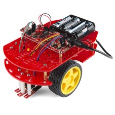
This code experiment uses a Sparkfun Redbot setup for line following. This is a two wheeled robot with 3 optical sensors to detect the line and an I2C accelerometer to sense bumping into objects. The computer is a Sparkfun Redbot Mainboard which is compatible with the Arduino Uno but provides a much different layout and includes a motor driver IC.

This robot is simple enough to make a manageable project but sufficiently complex to serve as a good test, especially when the project gets to the control system software. The basic code for handling these motors and sensors comes from Sparkfun and uses only the basic pin-level Arduino routines. I can’t possibly hack the entire Arduino code but using the Sparkfun code provides a manageable subset for experimenting.

For this article we’ll just look at the controlling the motors. Let’s start with the declaration of the Program class for testing the motor routines:

class Program {
public:
	void run();
	static Program& makeProgram() {
		static Program p;
		return p;
	}

private:
	Program() { }
	static constexpr int delay_time { 2000 };

	rm::Motor l_motor { l_motor_forward, l_motor_reverse, l_motor_pwm };
	rm::Motor r_motor { r_motor_forward, r_motor_reverse, r_motor_pwm };
	rm::Wheels wheels { l_motor, r_motor };

	void checkSerialInput();
};

There is a namespace rm enclosing the classes I’ve defined for the project, hence the rm:: prefacing the class names. On line 11 is something you may not have seen, a constexpr which is new in C++ 11 and expanded in C++14. It declares that delay_time is a true constant used during compilation and will not be allocated storage at run-time. There is a lot more to constexpr and we’ll see it more in the future. One other place I used it for this project is to define what pins to use. Here’s a sample:

constexpr int l_motor_forward = 2;
constexpr int l_motor_reverse = 4;
constexpr int l_motor_pwm = 5;
constexpr int r_motor_pwm = 6;
constexpr int r_motor_forward = 7;
constexpr int r_motor_reverse = 8;

The Motor class controls a motor. It requires two pins to control the direction and one pulse width modulation (PWM) pin to control the speed. The pins are passed via constructor and the names should be self-explanatory. The Wheels class provides coordinated movement of the robot using the Motor instances. The Motor instances are passed as references for the use of Wheels. Here are the two class declarations:

class Motor : public Device {
public:
	Motor(const int forward, const int reverse, const int pwm);

	void coast();
	void drive(const int speed);

	int speed() const {
		return mSpeed;
	}

private:
	void speed(const int speed);

	PinOut mForward;
	PinOut mReverse;
	PinOut mPwm;
	int mSpeed { };
};


class Wheels {
public:
	Wheels(Motor& left, Motor& right) :
			mLeft(left), mRight(right) {
	}

	void move(const int speed) {
		drive(speed, speed);
	}
	void pivot(const int speed) {
		drive(speed, -speed);
	}
	void stop() {
		mLeft.coast();
		mRight.coast();
	}

	void drive(const int left, const int right) {
		mLeft.drive(left);
		mRight.drive(right);
	}

private:
	Motor& mLeft;
	Motor& mRight;
};

The workhorse of Wheels is the function drive() which just calls the Motor drive() functions for each motor. Except for stop(), the other Wheels functions are utilities that use drive() and just make things easier for the developer. The compiler should convert those to a direct call to driver() since they are inline by being inside the class declaration. This is one of the interesting ways of using inline functions to enhance the utility of a class without incurring any cost in code or time.

The run() method in Program tests the motors by pivot()ing first in one direction and then the other at different speeds. A pivot() rotates the robot in place. Once the speed is set it continues until changed so the delay functions simply provide a little time for the robot to turn. Here’s the code:

void Program::run() {
	for (;;) {
		wheels.pivot(50);
		delay (delay_time);

		wheels.pivot(-100);
		delay(delay_time);

		checkSerialInput();
		if (serialEventRun) {
		}
	}
}

Wrap Up

The Redbot project is an interesting vehicle for demonstrating code techniques. The current test of the motor routines demonstrates how to override the existing Arduino main(). Even if you don’t like my approach with Program, the flexibility of using your own main() may come in handy for your own projects. The next article is going to revisit this program using templates.

THE EMBEDDING C++ PROJECT

Over at Hackaday.io, I’ve created an Embedding C++ project. The project will maintain a list of these articles in the project description as a form of Table of Contents. Each article will have a project log entry for additional discussion. Those interested can delve deeper into the topics, raise questions, and share additional findings.

The project also will serve as a place for supplementary material from myself or collaborators. For instance, someone might want to take the code and report the results for other Arduino boards or even other embedded systems. Stop by and see what’s happening.


Filed under: Arduino Hacks, Hackaday Columns, Software Development, software hacks

“It’s only software!” A sentence that strikes terror in the heart of an embedded systems software developer. That sentence is often uttered when the software person finds a bug in the hardware and others assume it’s going to be easier for fix in software rather than spin a new hardware revision. No wonder software is always late.

[Clint Stevenson] is his own hardware and software guy, as are most of us. He wanted to use the less expensive HC-SR04 ultrasonic rangefinder in a prototype. Longer term he wanted to have the choice of either a Parallax PING or MaxBotix ultrasonic sensor for their better performance outdoors. His hardware hack of the SR04 made this a software problem which he also managed to solve!

[Clint] was working with the Arduino library, based on the Parallax PING, which uses a single pin for trigger and echo. The HC-SR04 uses separate pins. Originally he modified the Arduino library to accept the two pin approach. But with his long term goal in mind, he also modified the HC-SR04 sensor by removing the on-board pull-up resistor and adding a new one on the connector side to combine the signals. That gave him an SR04 that worked with the single-pin based library.

We’ve seen Parallax PING projects for sensing water depth and to generate music. These could be hacked to use the HC-SR04 using [Clint’s] techniques.

[Arduino and HC-SR04 photo from http://www.blaxlab.com/%5D


Filed under: Arduino Hacks, Holiday Hacks, software hacks
Nov
24

Hack-a-Day Logo Laser Light Show

arduino hacks, laser, laser hacks, logo, Processing, scanning, servo, software hacks Comments Off on Hack-a-Day Logo Laser Light Show 

hackaday-laser-2

The Hack-a-Day logo challenge keeps on bearing fruit. This tip comes from [Enrico Lamperti] from Argentina who posted his follies as well as success creating a Hack-a-Day logo using a home built scanning laser projector.

The build consists of a couple small servos, a hacked up pen laser and an Arduino with some stored coordinates to draw out the image. As usual the first challenge is powering your external peripheral devices like servos. [Enrico] tackled this problem using 6 Ni-MH batteries and an LM2956 simple switcher power converter. The servos and Arduino get power directly from the battery pack and the Arduino controls the PWM signals to the servos as they trace out the stored coordinate data. The laser is connected to the servo assembly and is engaged and powered by an Arduino pin via an NPN transistor. He also incorporated a potentiometer to adjust the servo calibration point.

His first imported coordinate data generated from some Python script was not very successful. But later he used processing with an SVG file to process a click-made path the Arduino could use as map data to draw the Hack-a-Day logo. It requires a long exposure time to photograph the completed drawing in a dark room but the results are impressive.

It’s an excellent project where [Enrico] shares what he learned about using Servo.writeMicroseconds() instead of Servo.write() for performance along with several other tweaks. He also shared the BOM, Fritzing diagram, Processing Creator and Simulator tools and serial commands on GitHub. He wraps up with some options that he thinks would improve his device, and he requests any help others may want to provide for better performance. And if you want you could step it up a notch and create a laser video projector with an ATMega16 AVR microcontroller and some clever spinning tilted mirrors.


Filed under: Arduino Hacks, laser hacks, software hacks
Nov
15

tempescope_in_bookshelf

Most home weather displays use an LED screen or other moderately interesting methods of showing you what’s going on outside. The [Tempescope], however, takes an entirely different route, actually recreating a tiny weather environment on your bookshelf!

This active weather device is controlled via an Arduino as well as a pump, ultrasound diffuser, and other assorted components connected to a computer. It was originally meant to display, or more accurately recreate (precreate?) tomorrow’s weather. What is even more interesting is that using [World Weather] software, it’s able to simulate the weather on any place on earth.

Early in this article [Ken] lists the art of [bonsai] as one of his inspirations. He’s open to suggestions as to how to expand this device, which can be seen after the break. We (I at least) would think it was awesome if there was actually a bonsai tree in the environment in keeping with its influences. Certainly our readers can give him some feedback as well!


Filed under: arduino hacks, Featured, software hacks


  • Newsletter

    Sign up for the PlanetArduino Newsletter, which delivers the most popular articles via e-mail to your inbox every week. Just fill in the information below and submit.

  • Like Us on Facebook