CAN Bus is a small-scale networking standard, originally designed for cars now used for many robotics or sensor networks that need better range and addressing than I2C, and don’t have the pins or computational ability to talk on Ethernet.
The Adafruit CAN Bus BFF guide has everything you need to get started with using this BFF. There’s pages for overview, pinouts, CircuitPython, Arduino and resources for download.
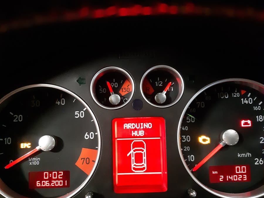
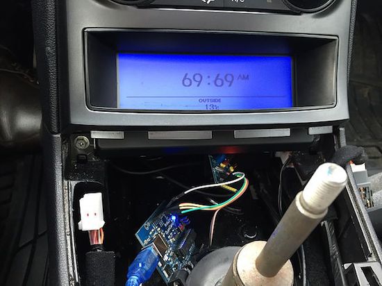
While it’s hard to beat analog instruments for instantaneous automotive feedback, Finnish electrical engineering student Jussi Ristiniemi also wanted a digital speed readout on his 2002 Audi TT.
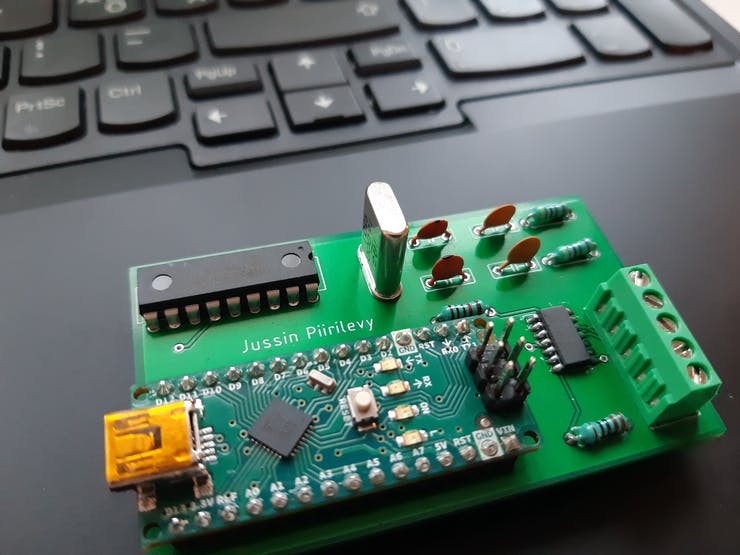
His particular model normally uses the car’s controller area network (CAN) to transmit the radio station or CD track to the uppermost section of the digital display. For this speedometer mod, audio data was replaced with “KM/H” readings, supplied by the vehicle’s CAN bus system via an Arduino Nano and custom interface shield.
Speeds can now be nicely shown in the center of the instrument cluster, letting the driver know exactly how fast they’re traveling. As it’s winter in Finland, and the TT is only driven during the summer, actual speed display has yet to be tested. However, with access to the car’s full CAN bus, any necessary tweaks should be trivial.
Whilst swapping out the stereo in his car for a more modern Android based solution, [Aaron] noticed that it only utilised a single CAN differential pair to communicate with the car as opposed to a whole bundle of wires employing analogue signalling. This is no surprise, as modern cars invariably use the CAN bus to establish communication between various peripherals and sensors.
In a series of videos, [Aaron] details how he used this opportunity to explore some of the nitty-gritty of CAN communication. In Part 1 he designs a cheap, custom CAN bus sniffer using an Arduino, a MCP2515 CAN controller and a CAN bus driver IC, demonstrating how this relatively simple hardware arrangement could be used along with open source software to decode some real CAN bus traffic. Part 2 of his series revolves around duping his Android stereo into various operational modes by sending the correct CAN packets.
These videos are a great way to learn some of the basic considerations associated with the various abstraction layers typically attributed to CAN. Once you’ve covered these, you can do some pretty interesting stuff, such as these dubious devices pulling a man-in-the-middle attack on your odometer! In the meantime, we would love to see a Part 3 on CAN hardware message filtering and masks [Aaron]!
In the old days, a physical button or switch on the dashboard of your car would have been wired to whatever device it was controlling. There was potentially a relay in the mix, but still, it wasn’t too hard to follow wires through the harness and figure out where they were going. But today, that concept is increasingly becoming a quaint memory.
Assuming your modern car even has physical buttons, pushing one of them likely sends a message over the CAN bus that the recipient device will (hopefully) respond to. Knowing how intimidating this can be to work with, [TJ Bruno] has been working on some software that promises to make working with CAN bus user interfaces faster and easier. Ultimately, he hopes that his tool will allow users to rapidly integrate custom hardware into their vehicle without having to drill a hole in the dashboard for a physical control.
But if you’re the kind of person who doesn’t like to have things done for them (a safe bet, since you’re reading Hackaday), don’t worry. [TJ] starts off his write-up with an overview of how you can read and parse CAN messages on the Arduino with the MCP2515 chip. He breaks his sample Sketch down line by line explaining how it all works so that even if you’ve never touched an Arduino before, you should be able to get the gist of what’s going on.
As it turns out, reading messages on the CAN bus and acting on them is fairly straightforward. The tricky part is figuring out what you’re looking for. That’s where the code [TJ] is working on comes in. Rather than having to manually examine all the messages passing through the network and trying to ascertain what they correspond to, his program listens while the user repeatedly presses the button they want to identify. With enough samples, the code can home in on the proper CAN ID automatically.
I am a crappy software coder when it comes down to it. I didn’t pay attention when everything went object oriented and my roots were always assembly language and Real Time Operating Systems (RTOS) anyways.
So it only natural that I would reach for a true In-Circuit-Emulator (ICE) to finish of my little OBDII bus to speed pulse generator widget. ICE is a hardware device used to debug embedded systems. It communicates with the microcontroller on your board, allowing you to view what is going on by pausing execution and inspecting or changing values in the hardware registers. If you want to be great at embedded development you need to be great at using in-circuit emulation.
Not only do I get to watch my mistakes in near real time, I get to make a video about it also.
Getting Data Out of a Vehicle
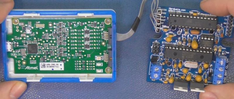
I’ve been working on a small board which will plug into my car and give direct access to speed reported on the Controller Area Network (CAN bus).
To back up a bit, my last video post was about my inane desire to make a small assembly that could plug into the OBDII port on my truck and create a series of pulses representing the speed of the vehicle for my GPS to function much more accurately. While there was a wire buried deep in the multiple bundles of wires connected to the vehicle’s Engine Control Module, I have decided for numerous reasons to create my own signal source.
At the heart of my project is the need to convert the OBDII port and the underlying CAN protocol to a simple variable representing the speed, and to then covert that value to a pulse stream where the frequency varied based on speed. The OBDII/CAN Protocol is handled by the STN1110 chip and converted to ASCII, and I am using an ATmega328 like found on a multitude of Arduino’ish boards for the ASCII to pulse conversion. I’m using hardware interrupts to control the signal output for rock-solid, jitter-free timing.
Walk through the process of using an In-Circuit Emulator in the video below, and join me after the break for a few more details on the process.
The Hardware
I revised the board since the last video and removed the support for the various protocols other than CAN, which is the non-obsolete protocol of the bunch. By removing a bunch of parts I was able to change the package style to through-hole which is easier for many home hobbyists, so you can leave the solder-paste in the ‘fridge.
The “Other Connector” on your Arduino
Unlike the Arduino which is ready to talk to your USB port when you take it out of the box, the ATmega chips arrive without any knowledge of how to go and download code, in other words it doesn’t have a boot loader. Consequently I have the In-Circuit-Serial-Programming (ICSP) pins routed to a pin header on my board so that I can program the part directly.
On this connector you’ll find the Reset line, which means with this header I can use a true ICE utilizing the debugWIRE protocol. Since the vast majority of designs that use an AVR chip do not repurpose the reset pin for GPIO, it is a perfect pin to use for ICE. All of the communications during the debug process will take place on the reset pin.
Enter the ICE
When designing a computer from scratch there is always the stage where nothing yet works. Simply put, a microprocessor circuit cannot work until almost every part of the design works; RAM, ROM, and the underlying buses all need to (mostly) work before simple things can be done. As a hardware engineer by trade I would always reach for an ICE to kick off the implementation; only after the Beta release would the ICE start to gather dust in the corner.
In the case of the ATmega, the debugging capabilities are built into the microcontroller itself. This is a much more straightforward implementation than the early days when we had to have a second isolated processor running off-board with its own local RAM/ROM.
One note mentioned in the video is that a standard Arduino’ish board needs to have the filter capacitors removed from the RESET line to allow the high speed data on the line for its debugWIRE usage.
The ICE I am using here is the one made by Atmel, and is compatible with Atmel Studio, there are also other models available such as the AVR Dragon.
ICEyness
The ICE allows us to download and single step our code while being able to observe and overwrite RAM and I/O Registers from the keyboard. We are able to watch the program step by step or look underneath at the actual assembly code generated by the compiler. We can watch variables and locations directly in RAM or watch the C language counterparts. It’s also possible to jump over a sub-routine call in the instance of just wanting to see the result without all of the processing.
This video was really about finishing the OBDII circuit so I didn’t really have the time to go over everything an ICE can do, maybe I will do a post dedicated to just the ICE and development environment next time.
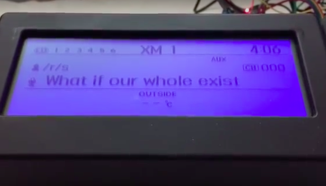
The Shower Thoughts subreddit is a collection of all those ideas or philosophical questions that race through your mind while in the bathroom. For example, “I like to think money wouldn’t change me; yet when I’m winning Monopoly I’m a terrible person,” or “12 years ago leaving CDs out in my car gave theives a reason to break in. Today, leaving CDs out is a deterrent.”
While most folks would simply browse Reddit on their phones or laptops, Harin De Mel decided to something a bit different. He managed to hack his vehicle’s dashboard to display some of the best thoughts from the last hour. Not a bad idea for when you’re stuck in traffic or sitting in the car waiting for someone to come outside, right?
The Maker sniffed the CAN bus on his 2012 Hyundai Genesis, and isolated the LCD from the rest of the network. He used Raspberry Pi and an Arduino, both of which are interfaced with an MCP2515 — one for the display, the other to receive signals from the original network. A Wi-Fi dongle on the Raspberry Pi enables Internet connectivity.
De Mel was also able to make the text scroll, which was accomplished through the CAN bus. However, Python script on the Raspberry Pi provided more control on how fast or frequently the message would come across the screen.
Now that I have a better understanding of how the LCD is controlled, I want to use the screen for more useful information. I have an in-dash Nexus 7 and would like to parse the information of the currently playing track to the car’s system as if it was an iPod. Frank Zhao was kind enough to leave a comment on my previous post pointing me in the direction of the Apple Accessories Protocol (AAP) which I will also begin to tinker with at some point in the future.
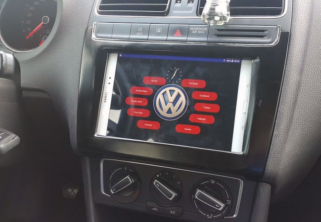
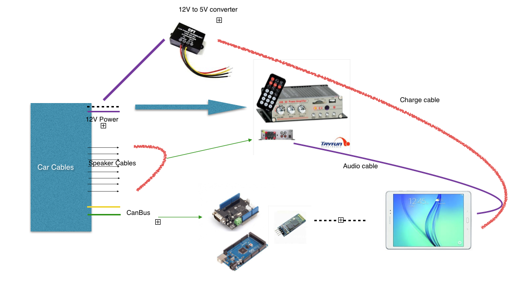
Unlike many cars today, Aykut Celik’s 2014 Volkswagen Polo didn’t have Bluetooth connectivity or an elaborate touchscreen navigation system. So, the Maker decided to take matters into his own hands and swapped out his “useless” radio for a Samsung tablet, putting Google Maps, Spotify and other apps right in his vehicle’s dashboard.
In order to accomplish this, Celik needed an amplifier (to replace the one attached to the prior radio), a CAN bus shield from Seeed (so he could use the steering wheel’s volume buttons), a Bluetooth module, and an Arduino Mega 2560 (for parsing data and sending it over to the Android device).
A CAN-BUS shield is necessary to be able to read CAN-BUS commands from the CAN bus line… I used this shield for detecting wheel button commands like volume up, mute and volume down. Behind the car radio there are two CAN bus cables. One of them is CAN bus – HIGH and the other is CAN bus – LOW. These cables must be connected to green sockets on the shield.
Using the SeeedCAN bus shield, you can sniff you car’s CAN bus data.
The info which is gathered from CAN bus is transferred to the Android tablet via Bluetooth. There is a little app which is responsible, for example, reducing volume whenever the wheel volume button is clicked. And a menu activity to open other apps.
The subreddit for Shower Thoughts offers wisdom ranging from the profound to the mundane. For example: “Every time you cut a corner you make two more.” Apparently, [Harin] has a bit of an addiction to the subreddit. He’s been sniffing the CAN bus on his 2012 Hyundai Genesis and decided to display the top Shower Thought on his radio screen.
To manage the feat he used both a Raspberry Pi and an Arduino. Both devices had a MCP2515 to interface with two different CAN busses (one for the LCD display and the other for control messages which carries a lot of traffic.
The code is available on GitHub. There’s still work to do to make the message scroll, for example. [Harin] has other posts about sniffing the bus, like this one.
At Hackaday we’re very happy to see the increasing number of open hardware devices that appear everyday on the internet, and we’re also quite thrilled about open-source electric cars. Pictured above is the GEVCU, an open source electric vehicle control unit (or ECU). It is in charge of processing different inputs (throttle position, brake pressure, vehicle sensors) then send the appropriate control commands to electric motor controllers (aka inverters) via CAN bus messages or digital / PWM signals.
The project started back in December 2012 and was originally based on an Arduino Due. Since then, the GEVCU went through several revisions and ultimately a complete custom board was produced, while still keeping the Cortex M3 ATSAM3X8E from the Due. As you may have guessed, the board also includes a Wifi transceiver so users may adjust the ECU parameters via a web based platform. All resources may be downloaded from the official GitHub.
Planet Arduino is, or at the moment is wishing to become, an aggregation of public weblogs from around the world written by people who develop, play, think on Arduino platform and his son. The opinions expressed in those weblogs and hence this aggregation are those of the original authors. Entries on this page are owned by their authors. We do not edit, endorse or vouch for the contents of individual posts. For more information about Arduino please visit www.arduino.cc
You are currently browsing the archives for the CAN BUS category.