Posts | Comments

Planet Arduino

Archive for the ‘USB’ Category

RP2040-GEEK

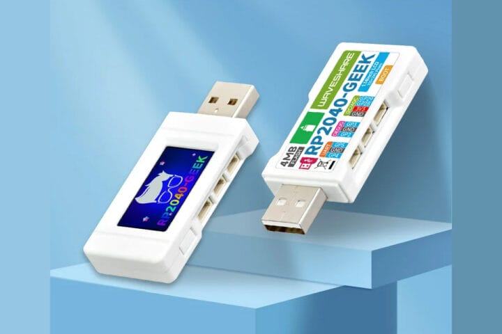
Waveshare RP2040-GEEK is a development board that looks like a USB flash drive but is based on a Raspberry Pi RP2040 microcontroller with a 1.14-inch 65K color LCD and some expansion ports all housed in a white plastic case. The device comes with a 4MB flash to store the firmware, a microSD card slot for data storage, a BOOT button to enter bootloader mode, two 3-pin connectors for UART and SWD debug, and a 4-pin I2C port. Waveshare RP2040-GEEK specifications: MCU – Raspberry Pi RP2040 dual-core Arm Cortex-M0+ microcontroller clocked up to 133 MHz with 264 kB SRAM Storage – 4MB flash (W25Q32JVSSIQ) and microSD card slot Display – 1.14-inch 240×135 pixel 65K color IPS LCD display USB – 1x USB Type-A female port for power and programming Debugging – 3-pin SWD port for connecting a target board; the standard CMSIS-DAP interface can be used to debug most Arm-based microcontrollers; [...]

The post Waveshare RP2040-GEEK USB development board features RP2040 MCU, 1.14-inch color display, UART/I2C/SWD ports appeared first on CNX Software - Embedded Systems News.

Smarter Serial Communications with WiSer

Surely you’ve been there: you need to capture serial output from a microcontroller or other device, so you reach for a PL2303 or CP210x or FT232RL-based USB-to-TTL serial cable (if you can remember where you put the damn thing after you last used it!) and…realize you don’t have the drivers installed on the computer you […]

The post Smarter Serial Communications with WiSer appeared first on Make: DIY Projects and Ideas for Makers.

Even for those of us who are fans of retrocomputing, it’s fair to say that not everyone plays their old-school games on real old-school hardware. The originals are now fragile and expensive, and emulators are good enough that if the gaming experience is all you’re after there’s little point in spending all that cash.

There’s one place in which the originals sometimes have the edge though, the classic controllers are the personal interface with the game. So when [Dome] found a SNES controller in an Akibahara shop, of course he picked it up. How to make it talk to a PC? Tuck an Arduino Pro Micro inside it, of course!

What we like about this project is that instead of ripping out the original electronics it instead hooks the Arduino board onto the original serial interface. We might have made a Nintendo socket to USB box to keep the original cable, but either way, the SNES (technically Super Famicom, because it’s a Japanese market unit) original stays true to its roots. The Arduino polls the clock line at the speed of the console, reads the result, and translates it to a USB interface for the computer. There’s a full run-down of the code and how it was made, should you wish to try.

Of course, if you don’t always have a PC handy, you could also put the whole computer in the controller.

top angle view of the featherwing

The Adafruit USB Host FeatherWing makes it easy to add USB Host support, especially now that TinyUSB supports it in the Arduino library as a ‘native’ interface for host support. This Wing uses the MAX3421E – a tried and true USB Host chip. It uses SPI plus an IRQ pin to send data to just about any USB device.

The Adafruit USB Host FeatherWing guide has everything you need to get started with using this FeatherWing. There’s pages for overview, pinouts, Arduino and resources for download.

Check out the full guide: Adafruit USB Host FeatherWing

Historically, there have been a few cases of useful wireless power transmission over great distances, like a team at MIT that was able to light up a 60 W bulb at several meters, and of course Nikola Tesla had grand dreams of drawing energy from the atmosphere. But for most of us wireless power is limited to small, short-range devices like cellphone chargers. While it’s not a lot of work to plug in a phone when it needs a charge, even this small task can be automated.

This build begins with a 3D printed cradle for the smartphone to sit in. When the device detects that the phone has been placed in the cradle, it uses a linear actuator to drive a custom-built charging cable into the phone’s USB port. Similarly, when the phone is lifted from the cradle the cable is automatically removed. It appears that there is some play in the phone’s position that lets the charger be plugged in smoothly, and the project’s creator [Larpushka] points out that the linear actuator is not particularly strong so we don’t imagine the risk of damage is very high.

While wireless charging still may have the edge when it comes to keeping debris out of the port, we still really enjoy a project like this that seems to be done for its own sake. There are some improvements that [Larpushka] plans to make, but for now we’re delighted by this build. For anyone looking to add true wireless charging to any phone that doesn’t have it, though, it’s not too difficult to accomplish either.

Need to hook a classic Mac mouse up to your modern machine with the help of a DIY USB adapter? [John Floren] has you covered. [John]’s solution uses a board with an ATmega32U4 microcontroller on it to connect to the Mac mouse on one end, and emulate a USB HID (Human Interface Device) on the other. A modern machine therefore recognizes it like it would any other USB input device.

Why is this necessary? The connector on the classic Mac mouse may look like a familiar DE-9 connector, but it is not an RS-232 device and wouldn’t work if it were plugged into a 9-pin serial port. The classic Mac mouse uses a different pinout, and doesn’t have much for brains on the inside. It relies on the host computer to read its encoders and button states directly.

This project is actually a bit of an update to a piece of earlier work [John] did in making a vintage Depraz mouse work with modern systems. He suspected that it wouldn’t take much to have it also work with a classic Mac mouse, and he was right — all it took was updating the pin connections and adding some pull-up resistors. The source code and design files are on GitHub.

Even if one does not particularly want to use a classic Mac mouse for daily work, there’s definitely value in this kind of thing for those who deal in vintage hardware: it allows one to function-check old peripherals without having to fire up a vintage machine.

Input devices consisting of optical readers for punched paper tape have been around since the earliest days of computing, so why stop now? [Jürgen]’s Paper Tape Reader project connects to any modern computer over USB, acting like a serial communications device. Thanks to the device’s automatic calibration, it works with a variety of paper materials. As for reading speed, it’s pretty much only limited to how fast one can pull tape through without damaging it.

Stacked 1.6 mm PCBs act as an enclosure, of sorts.

While [Jürgen]’s device uses LEDs and phototransistors to detect the presence or absence of punched holes, it doesn’t rely on hardware calibration. Instead, the device takes analog readings of each phototransistor, and uses software-adjusted thresholds to differentiate ones from zeros. This allows it to easily deal with a wide variety of tape types and colors, even working with translucent materials. Reading 500 characters per second isn’t a problem if the device has had a chance to calibrate.

Interested in making your own? The build section of the project has all the design files; it uses only through-hole components, and since the device is constructed from a stack of 1.6 mm thick PCBs, there’s no separate enclosure needed.

Paper tape and readers have a certain charm to them. Cyphercon 4.0 badges featured tape readers, and we’ve even seen the unusual approach of encoding an I2C byte stream directly onto tape.

[Daumemo] likes experimenting with DIY electronics, and like many people, eventually ran across an AVR microcontroller with a Unified Program and Debug Interface (UPDI). One option is of course to purchase an UPDI programmer, but an even better solution was to make a DIY USB version from nice, cheap parts.

Programming an Attiny404 over the UPDI interface.

UPDI is an interface for external programming and on-chip debugging of microcontrollers, and [Daumemo]’s solution is based on the jtag2updi project. It combines an Arduino Nano (in this case, a clone) with a single resistor, a single capacitor, and a six pin angled header (with a cleverly bent pin) to enable programming UPDI devices over a USB connection. [Daumemo] is happy to report that the device works just fine in both Microchip Studio with AVRDUDE, or PlatformIO.

Is an Arduino Nano a bit overpowered in this role? Maybe, but the price is certainly right. There’s no need for a custom PCB either, since everything can be soldered direct to the Nano board. A matching 3D printed enclosure is about all that’s needed to make a robust and reliable DIY USB UPDI programmer out of a handful of parts, and that sounds good to us.

On the other hand, if you do find yourself making custom PCBs, you may be interested in another of [Daumemo]’s DIY projects: a printable structure to turn a rotary tool into a PCB drill press.

Even with more and more devices making the leap to USB-C, the Arduino Uno still proudly sports a comparatively ancient Type-B port. It wouldn’t be a stretch to say that many Hackaday readers only keep one of these cables around because they’ve still got an Uno or two they need to plug in occasionally.

Looking to at least move things in the right direction, [sjm4306] recently set out to create a simple board that would let him mount a micro USB connector in place of the Uno’s original Type-B. Naturally there are no components on the PCB, it simply adapts the original through-hole footprint to the tight grouping of surface mount pads necessary to mount a female micro USB port.

Making castellated holes on the cheap.

The design is simple enough, but as [sjm4306] explains in the video below, there’s actually a bit more to the story than you might think. Looking to avoid the premium he’d pay to have the board house do castellated holes, he cheated the system a bit by having the board outline go right through the center of the standard pads.

Under a microscope, you can see the downside of this approach. Some of the holes got pretty tore up as the bit routed out the edges of the board, with a few of them so bad [sjm4306] mentions there might not be enough of the pad left to actually use. But while they may not be terribly attractive, most of them were serviceable. To be safe, he says anyone looking to use his trick with their own designs should order more boards than they think they’ll actually need.

Of course you could go all the way and retrofit the Uno with a USB-C port, as we’ve seen done with devices in the past. But the latest-and-greatest USB interface can be a bit fiddly, especially with DIY gadgets, so we can’t blame him for going with the more reliable approach.

We’ve all found ourselves swimming amongst too many similar-looking USB cables over the years. Some have all the conductors and functionality, some are weird power-only oddballs, and some charge our phones quickly while others don’t. It’s a huge headache and one that [TechKiwiGadgets] hopes to solve with the Arduino Cable Tracer.

The tracer works with USB-A, Mini-USB, Micro-USB, and USB-C cables to determine whether connections are broken or not and also to identify wiring configurations. It’s built around the Arduino Mega 2560, which is ideal for providing a huge amount of GPIO pins that are perfect for such a purpose. Probing results are displayed upon the 2.8″ TFT LCD display that makes it easy to figure out which cables do what.

It’s a tidy build, and one that we could imagine would be very useful for getting a quick go/no-go status on any cables dug out of a junk box somewhere. Just remember to WIDLARIZE any bad cables you find so they never trouble you again. Video after the break.


  • Newsletter

    Sign up for the PlanetArduino Newsletter, which delivers the most popular articles via e-mail to your inbox every week. Just fill in the information below and submit.

  • Like Us on Facebook