Posts | Comments

Planet Arduino

Archive for the ‘update’ Category

Remote monitoring with a mobile app is a must for all the IoT device management platforms. In general, having a mobile app offers a more complete and convenient user experience for IoT device management platform users, which can improve their satisfaction and loyalty. So expanding the mobile app capabilities in order to help users interact better with the platform is one of the key goals. 

The Arduino IoT Remote app (available for Android and iOS) was designed with the aim to control and monitor your devices using the Arduino Cloud dashboards and offer full control in your hands from anywhere in the world. Arduino has gone a BIG step further and enabled you to use the app as an IoT device, collecting information from the mobile phone sensors and sending them to the Arduino Cloud, where they can be monitored and recorded. This feature automatically creates in the Arduino Cloud everything needed to monitor the sensors (the Device, the Thing, and a dashboard).

Starting to play with real hardware can be tricky for non-experienced users, so this feature enables users to get familiar with the Arduino Cloud device management environment using their own phone. Easy, right?

This feature was limited to having the app open at all times. But, what if you wanted to use your mobile phone’s sensors to be monitored continuously thereby enabling them to be used for real projects? For that, you’d need to run the app in background mode.

Voilà… the new background mode!

Now, you have the possibility to run the Arduino IoT Remote app in the background on demand. With this feature, your phone sensors are polled continuously and the data is sent to the Arduino Cloud in real-time. The polling periodicity and the thresholds have been smartly defined in order to optimize the battery consumption, and the feature can be enabled or disabled as desired.

The key benefits of the original “Use data from your phone” feature are still available, in that you can automatically see your phone as a usable device in the IoT cloud, along with a number of variables automatically created and associated with it. Those variables are associated with some of the sensors in your phone such as accelerometer, GPS, microphone, compass, or barometer. Additionally, a dashboard is also automatically created so that all those variables can be monitored.

Do you need some inspiration?

Unleash your creativity with the new feature! With it, a whole new world of possibilities opens up. You can now develop applications that merge data from your phone with real-world actions. Here are some examples:

  • Geofencing: Use virtual geographic boundaries to trigger actions based on your location.
  • Home automation: Automate tasks at home based on your location. For example, turn lights off when you leave and on when you return, lock doors, and adjust home climate control.
  • Child/elder care: Keep track of loved ones with geofencing. Get instant notifications if they leave designated areas.
  • Accident detection: Use your phone’s accelerometer to detect sharp decelerations and detect accidents or falls.
  • Gaming: Use your phone as a remote control for a robot or a game. The sky’s the limit!

Only your imagination sets the boundaries of what you can do with this new feature.

Fall detection project

Fall detection using your phone and Arduino Cloud

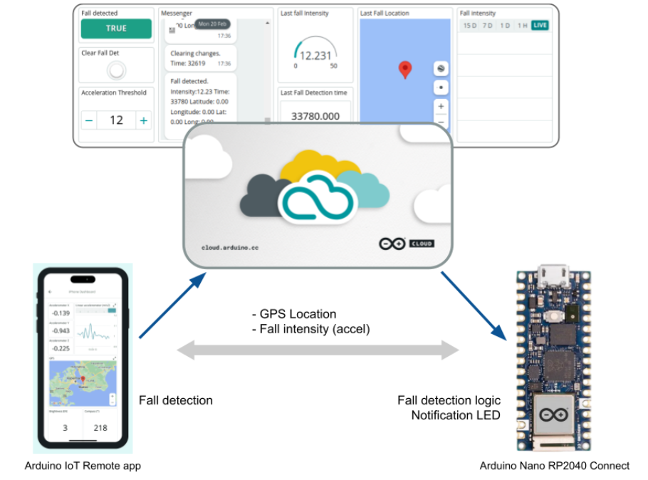
Short of ideas? No worries! Check out this project out if you want to see a real use case and give it a try. This project demonstrates how to use your mobile phone as an IoT device using the phone device feature. By streaming data from your phone’s accelerometer to the Cloud and using an Arduino Nano RP240 Connect, a fall detection system is formed. If sudden acceleration is detected above a certain threshold, an LED on the board is switched on to alert anyone nearby

How do I get started?

Working with the Phone as a background device is a simple process. However, before you begin, ensure that you have the latest version of the app installed on your device. It’s worth noting that the app is compatible with both Android and iOS. platforms.

Enable the “Phone as Device” feature

To proceed, navigate to the “Phone as Device” option on the app’s navigation bar, then follow the instructions to grant the app access to your phone’s sensors.

Enable the Phone as Device feature on the Arduino IoT Cloud remote app

Enable the background mode

Once you’ve completed the previous step, you’ll receive a prompt to enable the “Background mode” feature. You can either activate it immediately or do so manually at a later time. You can also select how your device will stream data to the IoT Cloud:

  • Periodically: Data will be streamed to the cloud at regular intervals that you specify.
  • On change: Data will be streamed to the cloud whenever there is a change in the value being measured.
Enable the background mode of the Phone as Device feature on the Arduino IoT Cloud remote app

Start playing with your dashboards

You now can go to your automatically created dashboard and check how your phone sensors are monitored according to the rules you have configured.

Enable the background mode of the Phone as Device feature on the Arduino IoT Cloud remote app

Arduino IoT Cloud Remote dashboards

Learn more

If you want to learn more about the “Phone as Device”  feature and the background mode, we recommend reviewing the article on the documentation. Kindly note that the Background mode is a feature that comes with the Maker plan or higher. However, we strongly recommend it to anyone seeking anyone looking to enhance their projects using their phone data. Upgrading to a paid subscription is a straightforward process, and you’ll receive extra features to maximise our platform’s capabilities.

To learn more about the Arduino IoT Cloud, please visit the official documentation and resources available on the Arduino Cloud web site.

The post Get more out of your phone: Integrate it with your Arduino Cloud projects appeared first on Arduino Blog.

Potentially, one of the great things about having a device connected to the network is that you can update it remotely. However, how do you make that happen? If you use the Arduino setup for the ESP8266 or ESP32, you might try [scottchiefbaker’s] library which promises to make the process easy.

Adding it looks to be simple. You’ll need an include, of course. If you don’t mind using port 8080 and the path /webota, you only need to call handle_webota() from your main loop. If you want to change the defaults, you’ll need to add an extra call in your setup. You also need to set up a few global variables to specify your network parameters.

The only caveat is that long delay statements in your loop can block things from working and aren’t a great idea anyway. If you have them, you can replace all your delay calls with webota_delay which will stop the system from ignoring update requests.

The code started from a different online tutorial but packaged the code up nicely for reuse. To do an update, simply navigate to the device with a web browser and use the correct port number and path. From there you can upload a new binary image taken from the Arduino IDE with the export compiled binary command.

The only concern we saw was the code didn’t appear to authenticate you at all. That means anyone could load code into your ESP. That might be ok on a private network, but on the public Internet it is surely asking for trouble. The original tutorial code did have a hardcoded user and password, but it didn’t look very useful as the password was in the clear and didn’t stop you from uploading if you knew the right URL. Dropping it from the library probably makes sense, but we would want to build some kind of meaningful security into anything we deployed.

If you have a network connection, we’ve seen the same trick done with a normal Arduino with a wireless chip. You can even do it over WiFi but using an ESP8266 which you’ll then want to be able to update, too.

downloadIDE_blogpost_1-6-9
Today, we’re releasing a shiny new version of the Arduino IDE, with the usual plethora of features and bug fixes.

The new Yún Shield allows you to upload a sketch over the air on any supported board so, as you can guess, our official cores were updated to support this feature. 

Simply select the YunShield entry from the Network port menu, the base board from the Board menu, press upload and voilà!

3

You can update the cores via Board Manager to get the latest version (1.6.11 for AVR, 1.6.8 for SAM and 1.6.6 for SAMD) but don’t miss the chance to update the IDE itself. ;-)

This release fixes a bunch of long-standing issues:

  • the update popup is no longer always on top, error reporting on multitab sketches now works correctly, and compiling/uploading flows have been revisited
  • the problem with FTDI serial ports on Windows introduced with IDE 1.6.8 has been fixed as well
  • the AVR core now recognizes if a new bootloader is present and uses a safe RAM location to trigger programming (this is particularly important for large sketches, like the ones produced by our friends at Arduboy)
  • the builder has been patched, and is now faster and easier to hack

Release after release the community effort continues to get stronger and that makes us extremely happy! As usual, be sure to check the whole changelog for a complete list of changes and credits.

Don’t forget to report any issue you may find, either on GitHub or on the Arduino forum: your help is very much appreciated — even if you’re not a tech specialist. And please consider supporting the Arduino Software by contributing to its development!

Download IDE 1.6.9 now and happy coding! (You can also read all about the new Yún Shield here.)

Arduino IDE 1.6.6 Serial PlotterArduino releases version 1.6.6 of their IDE software, adding new tools and features for programming Arduino-compatible microcontrollers.

Read more on MAKE

The post Arduino Software Update Introduces Command-Line Tool, Serial Data Plotter appeared first on Make: DIY Projects, How-Tos, Electronics, Crafts and Ideas for Makers.

Nov
29

Arduino Aircraft Stabilization Code

gallery, plane, stabilization, update, yellow plane Comments Off on Arduino Aircraft Stabilization Code 

We remember [nickatredbox] for the [Yellow Plane],  an Arduino project. Today we have an update to the code. Click on [more] for the full code update.

Revised Yellow FPV Plane with gyro stability system added, Worked best with analogue inputs from Murata piezo gyro sensors of a dead KK board filtered taking a 10 point average. Yaw compensation is currently not used as there is no rudder presently.

Here is a video of the functionality

Here is the Arduino code that calculates the trim values

//Use the pot as the gain for all channels for now
float GainPot = (float)(TxVal[2]) * 0.001f;

//Get the target values from the TX
int PitchTarg = (TxVal[3] / 10);
int RollTarg = (TxVal[4] / 10);
int YawTarg = (TxVal[6] / 10);

//Prime the Target WOZ values
if(PitchTargWOZ == 9999)
PitchTargWOZ = PitchTarg;

if(RollTargWOZ == 9999)
RollTargWOZ = RollTarg;

if(YawTargWOZ == 9999)
YawTargWOZ = YawTarg;

//Get the Centered target values
float PitchTargCentred = (float)(PitchTarg – PitchTargWOZ);
float RollTargCentred = (float)(RollTarg – RollTargWOZ);
float YawTargCentred = (float)(YawTarg – YawTargWOZ);

//Calculate gains
float PitchGain = GainPot * 1.0f;
float RollGain = GainPot * 1.0f;
float YawGain = GainPot * 1.0f;

//Get Gyro values
float PitchGyro = (float)(AnIn[2] – AnInWOZ[2]);
float RollGyro = (float)(AnIn[1] – AnInWOZ[1]);
float YawGyro = (float)(AnIn[0] – AnInWOZ[0]);

//Calc P error
float PitchError = (float)PitchTargCentred + PitchGyro;
float RollError = (float)RollTargCentred + RollGyro;
float YawError = (float)YawTargCentred + YawGyro;

//Apply gains
int PitchTrim = (int)(PitchError * PitchGain);
int RollTrim = (int)(RollError * RollGain);
int YawTrim = (int)(YawError * YawGain);

//Constaring trim authority
PitchTrim = constrain(PitchTrim, -30, 30);
RollTrim = constrain(RollTrim, -30, 30);
YawTrim = constrain(YawTrim, -30, 30);

//Dump the trim value
if((TxVal[9] & 0×4) == 0)
{
PitchTrim = 0;
RollTrim = 0;
YawTrim = 0;
}

Here is all the RX the code

#define MAX_CHAN 12
#define MAX_IN_STR 200
#define MAX_SETTINGS 20
#define MAX_NAV_VALS 50
#define MAX_SAMPLE 10

#include

char buf[255] = {0, };
String str = “”;
char *p;

Servo servo[7]; // create servo object to control a servo
int val = 0; // variable to read the value from the analog pin
int AnInWOZ[MAX_CHAN] = {0, };
int AnIn[MAX_CHAN] = {0, };
int AnInBuf[MAX_CHAN] = {0, };

//Get the target values from the TX at rest
int PitchTargWOZ = 9999;
int RollTargWOZ = 9999;
int YawTargWOZ = 9999;

String inputString = “”; // a string to hold incoming data

int Sample = 0;
int TxTemp[MAX_CHAN + 1] = {0, };
int TxVal[MAX_CHAN + 1] = {0, };

int NavVal[MAX_NAV_VALS] = {0, };
int SettingVal[MAX_SETTINGS] = {0, };

int rssiDur = 0;
int DigBits = 0;
int ComState = 0;
long PacketCount = 0;
long NoPacketCount = 0;

//Digital inputs TX code helper
//TxVal[8] |= (digitalRead(5) << 0);//joy 2 push
//TxVal[8] |= (digitalRead(6) << 1);//pb
//TxVal[8] |= (digitalRead(7) << 2);//slide
//TxVal[8] |= (digitalRead(8) << 3);//toggle

void setup() {

// initialize serial:
Serial.begin(38400);

// reserve 200 bytes for the inputString:
inputString.reserve(MAX_IN_STR);

pinMode(2,INPUT);//rssi
digitalWrite(2, HIGH);

servo[0].attach(3); // attaches the servo on pin 3 to the servo object
servo[1].attach(5); // attaches the servo on pin 5 to the servo object
servo[2].attach(6); // attaches the servo on pin 6 to the servo object
servo[3].attach(9); // attaches the servo on pin 9 to the servo object
servo[4].attach(10); // attaches the servo on pin 10 to the servo object
servo[5].attach(11); // attaches the servo on pin 11 to the servo object

NullServos();

//Get all the analogue signals
//Do a wind off zero

for(int i = 0;i < 8;i++)
AnInWOZ[i] = 0;

for(int i = 0;i < MAX_SAMPLE;i++){

AnIn[0] += analogRead(A0);
AnIn[1] += analogRead(A1);
AnIn[2] += analogRead(A2);
AnIn[3] += analogRead(A3);
AnIn[4] += analogRead(A4);
AnIn[5] += analogRead(A5);
AnIn[6] += analogRead(A6);
AnIn[7] += analogRead(A7);

delayMicroseconds(10);
}

for(int i = 0;i < 8;i++)
AnInWOZ[i] = (AnIn[i] / MAX_SAMPLE);

//Prime the WOZ values
PitchTargWOZ = 9999;
RollTargWOZ = 9999;
YawTargWOZ = 9999;

}

void loop(){

//*Get all the analogue signals
for(int i = 0;i < 8;i++)
AnInBuf[i] = 0;

for(int i = 0;i < MAX_SAMPLE;i++){

AnInBuf[0] += analogRead(A0);
AnInBuf[1] += analogRead(A1);
AnInBuf[2] += analogRead(A2);
AnInBuf[3] += analogRead(A3);
AnInBuf[4] += analogRead(A4);
AnInBuf[5] += analogRead(A5);
AnInBuf[6] += analogRead(A6);
AnInBuf[7] += analogRead(A7);

delayMicroseconds(10);
}

for(int i = 0;i < 8;i++)
AnIn[i]= (AnInBuf[i] / MAX_SAMPLE);

//Capture the Xbee comms
int CharCount = 0;

while ((Serial.available()) && ((++CharCount) 0)
inputString += inChar;

if(inputString.length() >= MAX_IN_STR)
break;

//Detect end of packet
if ( (inChar == ‘\n’) && (ComState > 0) )
{
//Serial.println(inputString);

//Count packets
PacketCount++;

int NumChan = ExtractPacket();

//Tramsmitter
if( ComState == 1)
{
for(int i = 0 ;i < NumChan;i++)
TxVal[i] = TxTemp[i];

DoTelemetery();

UpdateServos();

}//Navigator
else if( ComState == 2)
{
for(int i = 0 ;i < NumChan;i++)
NavVal[i] = TxTemp[i];

}//Settings
else if( ComState == 3)
{
for(int i = 0 ;i 50)
{
NullServos();
SoftReset();
}

//delayMicroseconds(1000);
}

int ExtractPacket()
{

int Lchk = 0;
int channel = 0; //initialise the channel count

p = &inputString[0];

while ((str = strtok_r(p, “,”, &p)) != NULL) // delimiter is the comma
{

TxTemp[channel] = str.toInt(); //use the channel as an index to add each value to the array

Lchk += TxTemp[channel];

channel++; //increment the channel

if(channel > MAX_CHAN)
break;
}

p = NULL;
inputString = “”;

//Process in comming data
if(channel > 2)
{
//Remove the remote chk from the total
Lchk -= TxTemp[channel-2];

//Checksum
if((Lchk – TxTemp[channel-2]) == 0)
return channel;

}

return -1;
}

void DoTelemetery()
{

//Send back a telemetery packet
if((PacketCount % 5) == 0)
{
rssiDur = pulseIn(5, LOW, 200);

int PacketType = 12;

//sprintf(buf, “T%02X,%d,%d,%d,%d,%d,%d,%d,%d,%d,%d,%d,%d,%d,%d,%d,%d,%d,%d,\n”, PacketType, rssiDur, PacketCount, NoPacketCount, TxVal[1], TxVal[2], TxVal[3], TxVal[4], TxVal[5], TxVal[6], AnIn[0], AnIn[1], AnIn[2], AnIn[3], AnIn[4], AnIn[5], AnIn[6], AnIn[7], DigBits);
//sprintf(buf, “T %d,%d,%d,%d,%d,%d,%d,%d,%d,%d,%d,%d,%d,%d,\n”, PacketType, rssiDur, PacketCount, NoPacketCount, AnIn[0], AnIn[1], AnIn[2], AnIn[3], AnIn[4], AnIn[5], AnIn[6], AnIn[7], DigBits, TxVal[9]);
sprintf(buf, “T%02X%02X%04X%02X%03X%03X%03X%03X%03X%03X%03X%03X%03X%02X%02X\n”, PacketType, rssiDur, PacketCount, NoPacketCount, AnIn[0], AnIn[1], AnIn[2], AnIn[3], AnIn[4], AnIn[5], AnIn[6], AnIn[7], DigBits, TxVal[9]);

Serial.write(buf);

if(digitalRead(13) == false)
digitalWrite(13, HIGH); // set the LED on
else
digitalWrite(13, LOW); // set the LED off

}
}

void UpdateServos()
{

//Digital inputs TX code helper
//TxVal[8] |= (digitalRead(5) << 0);//joy 2 push
//TxVal[8] |= (digitalRead(6) << 1);//pb
//TxVal[8] |= (digitalRead(7) << 2);//slide
//TxVal[8] |= (digitalRead(8) << 3);//toggle

//Throttle TxVal[1]
//Rotary pot TxVal[2]
//Joy 1 X TxVal[3]
//Joy 1 Y TxVal[4]
//Joy 2 X TxVal[5]
//Joy 2 Y TxVal[6]
//rssi TxVal[7]
//digital TxVal[8]
//micros() TxVal[9]

//Use the pot as the gain for all channels for now
float GainPot = (float)(TxVal[2]) * 0.001f;

//Get the target values from the TX
int PitchTarg = (TxVal[3] / 10);
int RollTarg = (TxVal[4] / 10);
int YawTarg = (TxVal[6] / 10);

//Prime the Target WOZ values
if(PitchTargWOZ == 9999)
PitchTargWOZ = PitchTarg;

if(RollTargWOZ == 9999)
RollTargWOZ = RollTarg;

if(YawTargWOZ == 9999)
YawTargWOZ = YawTarg;

//Get the Centered target values
float PitchTargCentred = (float)(PitchTarg – PitchTargWOZ);
float RollTargCentred = (float)(RollTarg – RollTargWOZ);
float YawTargCentred = (float)(YawTarg – YawTargWOZ);

//Calculate gains
float PitchGain = GainPot * 1.0f;
float RollGain = GainPot * 1.0f;
float YawGain = GainPot * 1.0f;

//Get Gyro values
float PitchGyro = (float)(AnIn[2] – AnInWOZ[2]);
float RollGyro = (float)(AnIn[1] – AnInWOZ[1]);
float YawGyro = (float)(AnIn[0] – AnInWOZ[0]);

//Calc P error
float PitchError = (float)PitchTargCentred + PitchGyro;
float RollError = (float)RollTargCentred + RollGyro;
float YawError = (float)YawTargCentred + YawGyro;

//Apply gains
int PitchTrim = (int)(PitchError * PitchGain);
int RollTrim = (int)(RollError * RollGain);
int YawTrim = (int)(YawError * YawGain);

//Constaring trim authority
PitchTrim = constrain(PitchTrim, -30, 30);
RollTrim = constrain(RollTrim, -30, 30);
YawTrim = constrain(YawTrim, -30, 30);

//Dump the trim value
if((TxVal[9] & 0×4) == 0)
{
PitchTrim = 0;
RollTrim = 0;
YawTrim = 0;
}

//Calc flap anglke
int Flaps = 0;

//Apply flaps
if((TxVal[9] & 0×8) != 0)
Flaps = 25;

//Throttle
val = TxVal[1] / 10;
val = map(val, 1, 179, 30, 179);
val = constrain(val, 1, 165); // scale it to use it with the servo (value between 0 and 180)
servo[0].write(val); // sets the servo position according to the scaled value

//Elevator Joy 1 Y TxVal[4]
val = PitchTarg + PitchTrim;
val = constrain(val, 15, 165);
val = map(val, 0, 179, 135, 45); // scale it to use it with the servo (value between 0 and 180)
servo[1].write(val); // sets the servo position according to the scaled value

//Left Flaperon
val = RollTarg + Flaps + RollTrim;
val = constrain(val, 15, 165);
val = map(val, 0, 179, 165, 15); // scale it to use it with the servo (value between 0 and 180)
servo[2].write(val); // sets the servo position according to the scaled value

//Right Flaperon
val = RollTarg – Flaps + RollTrim;
val = constrain(val, 15, 165);
val = map(val, 0, 179, 165, 15); // scale it to use it with the servo (value between 0 and 180)
servo[3].write(val); // sets the servo position according to the scaled value

//Joy 2 x nose Wheel / rudder
val = (TxVal[6] / 10);
val = map(val, 0, 179, 55, 125);
servo[4].write(val); // sets the servo position according to the scaled value

//Joy 2 Y
val = TxVal[5] / 10;
val = constrain(val, 15, 165); // scale it to use it with the servo (value between 0 and 180)
servo[5].write(val); // sets the servo position according to the scaled value

}

void NullServos()
{

//Throttle TxVal[1]
//Rotary pot TxVal[2]
//Joy 1 X TxVal[3]
//Joy 1 Y TxVal[4]
//Joy 2 X TxVal[5]
//Joy 2 Y TxVal[6]
//rssi TxVal[7]
//digital TxVal[8]
//micros() TxVal[9]

//Throttle
val = 0;
val = map(val, 1, 179, 30, 179);
val = constrain(val, 1, 179); // scale it to use it with the servo (value between 0 and 180)
servo[0].write(val); // sets the servo position according to the scaled value

//Elevator Joy 1 Y TxVal[4]
val = 90;
val = constrain(val, 1, 179); // scale it to use it with the servo (value between 0 and 180)
servo[1].write(val); // sets the servo position according to the scaled value

//Left Flaperon
val = 90;
val = map(val, 0, 179, 1, 179); // scale it to use it with the servo (value between 0 and 180)
servo[2].write(val); // sets the servo position according to the scaled value

//Right Flaperon
val = 90;
val = constrain(val, 1, 179); // scale it to use it with the servo (value between 0 and 180)
servo[3].write(val); // sets the servo position according to the scaled value

//Joy 2 X
val = 90;
val = constrain(val, 1, 179); // scale it to use it with the servo (value between 0 and 180)
servo[4].write(val); // sets the servo position according to the scaled value

//Joy 2 Y
val = 90;
val = constrain(val, 1, 179); // scale it to use it with the servo (value between 0 and 180)
servo[5].write(val); // sets the servo position according to the scaled value

}

void SoftReset() // Restarts program from beginning but does not reset the peripherals and registers
{

//Prime the WOZ values
PitchTargWOZ = 9999;
RollTargWOZ = 9999;
YawTargWOZ = 9999;

NoPacketCount = 0;

asm volatile (” jmp 0″);
}


  • Newsletter

    Sign up for the PlanetArduino Newsletter, which delivers the most popular articles via e-mail to your inbox every week. Just fill in the information below and submit.

  • Like Us on Facebook