26
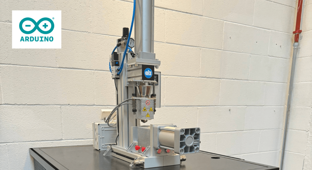
Most ski lifts are pretty simple systems: they use big ol’ motors to pull cables with chairs or hangers attached. More advanced detachable designs let the chairs come off the cable temporarily while in the terminal, so skiers can hop on at a leisurely pace. But basic fixed-grip chairlifts don’t have that capability and skiers have to jump on while the chairs move at full speed. To help ski lift operators space those chairs properly, Marc Antaya designed the Ski Lift Spacer 2000.
Antaya was working as a liftie at a local ski area and noticed that it was difficult to attach chairs to the ski lift cable at consistent intervals that facilitate smooth operation. So he built the Ski Lift Spacer 2000, which measures the cable speed and distance traveled, calculates the spacing, and stops the lift at the right times to hang the chairs. It is wired in series with the lift’s existing controls, so it can’t override their safety measures. It simply provides a remote start/stop function, which it can perform when desired for attaching chairs.
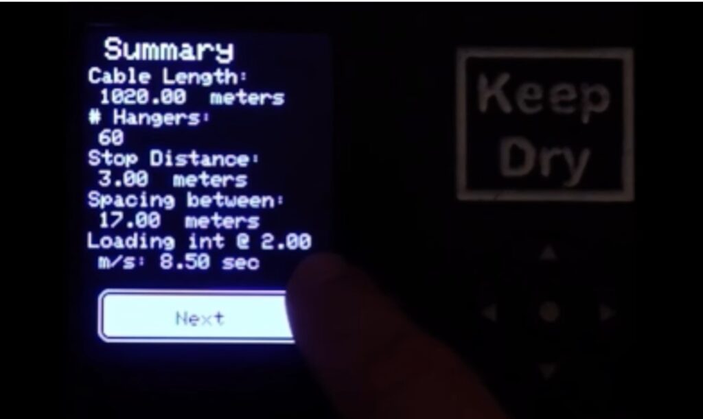
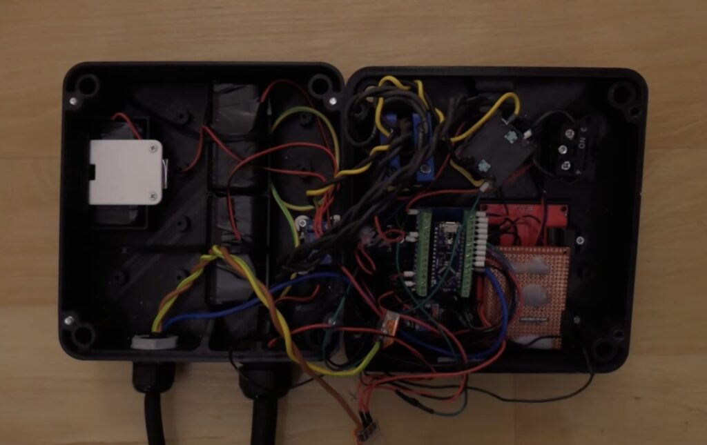
The device consists of an Arduino Nano Every board, lithium batteries, relays, an LCD screen, and a control interface. That interface is important, because it lets lifties calculate the chair positions in several different ways based on the data they have available. For example, they can start with a certain number of chairs and the cable length. In that case, the device will calculate the spacing between chairs. Or they can enter the cable length and desired spacing, in which case the device will calculate the total number of chairs required.
To do its job, the device needs to know exactly how much the cable moves. To achieve that, Antaya built a wheel turned by the cable. It has magnets, which the Arduino can use for rotational encoding thanks to Hall effect sensors. This is all configurable in the device menu system, where the liftie can set the wheel circumference/diameter and number of magnets.
Antaya has already tested an earlier version of the Ski Lift Space 2000 at his local ski area. After updating it as shown in the video, it is ready for a second round of testing.
The post This device helps ski lift operators attach chairs to the cable appeared first on Arduino Blog.