
Dec
02
02
Yellow Plane 2 with inverted V tail software modified and tested stability gyros
2.4GHz, arduino, arduino nano, dtb850, FPV, inverted vee tail, scratch build, Turnigy dlux 30A SBEC Brushless Speed Controller, twin boom, xBee, XBee Explorer Regulated, XBee Pro 60mW U.FL Connection - Series 1 Comments Off on Yellow Plane 2 with inverted V tail software modified and tested stability gyros
New Code
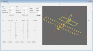
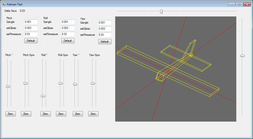
Kalman Filter
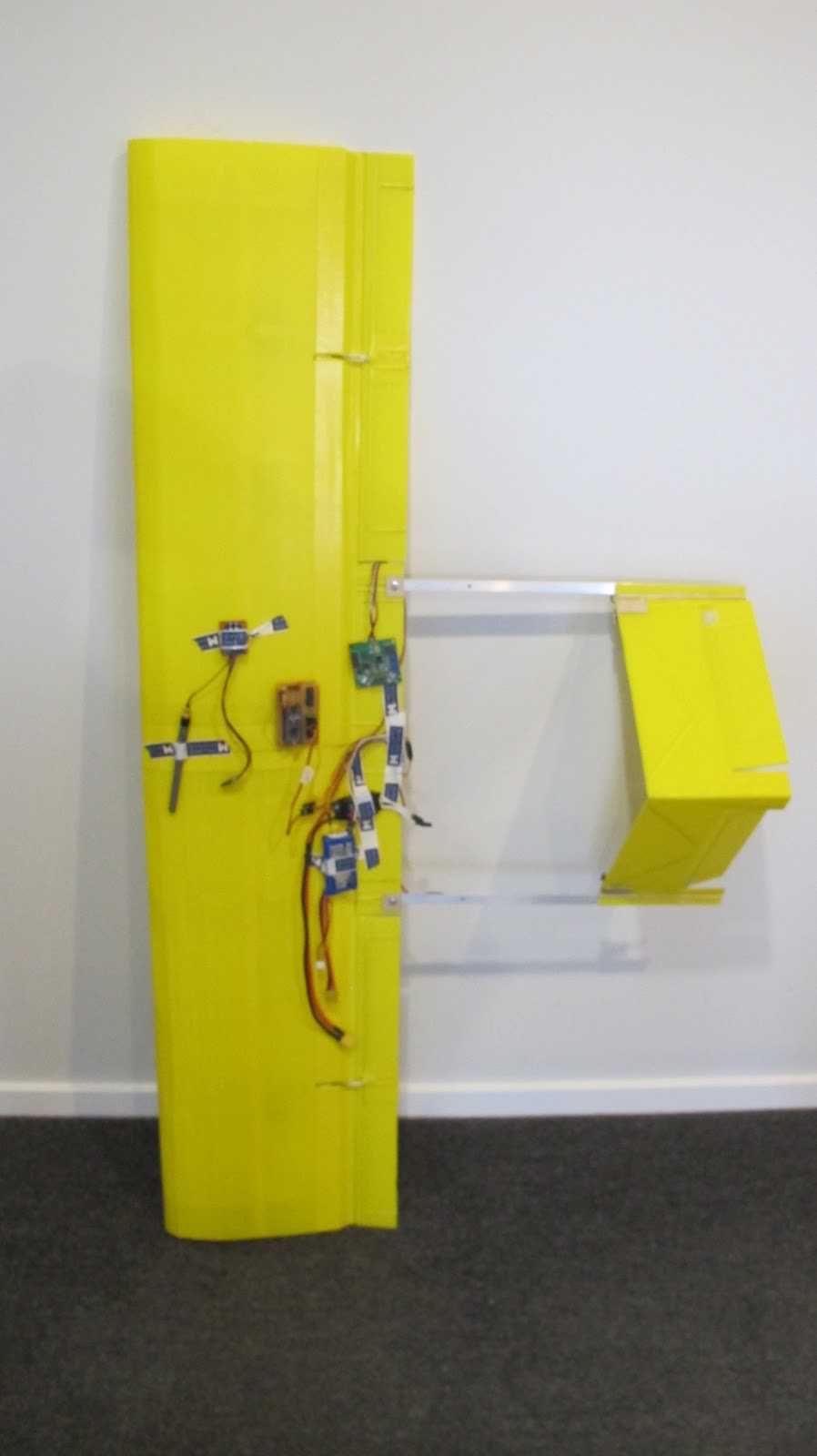
New parts
Turnigy L3010C-1300kv (420w)
H-KING 50A Fixed Wing Brushless Speed Controller
ZIPPY Compact 2700mAh 3S 25C Lipo Pack
HobbyKing 929MG Metal Gear Servo 2.2kg/ 12.5g/ 0.10sec
Dimentions
AUW 1521 Grams Wing loading 14.83 oz/ft² power to weight 270 Watts A Kg should perform much better than Yellow plane one.


Kalman Filter
This is the code in the main loop UpdateServos()
unsigned long msDelta = LastMicros - micros();
LastMicros = micros();
//Measure time since last cycle
double dt = (double)msDelta / 1000000.0;
// The angle should be in degrees and the rate should be in degrees per second and the delta time in seconds
double X_Angle = (double)AnIn[0];
double X_Rate = (double)AnIn[4];
double Kalman_X = kalman[0].getAngle(X_Angle, X_Rate, dt);
double Y_Angle = (double)AnIn[1];
double Y_Rate = (double)AnIn[5];
double Kalman_Y = kalman[1].getAngle(Y_Angle, Y_Rate, dt);
double Z_Angle = (double)AnIn[2];
double Z_Rate = (double)AnIn[6];
double Kalman_Z = kalman[2].getAngle(Z_Angle, Z_Rate, dt);
/* Copyright (C) 2012 Kristian Lauszus, TKJ Electronics. All rights reserved.
This software may be distributed and modified under the terms of the GNU
General Public License version 2 (GPL2) as published by the Free Software
Foundation and appearing in the file GPL2.TXT included in the packaging of
this file. Please note that GPL2 Section 2[b] requires that all works based
on this software must also be made publicly available under the terms of
the GPL2 ("Copyleft").
Contact information
-------------------
Kristian Lauszus, TKJ Electronics
Web : http://www.tkjelectronics.com
e-mail : kristianl@tkjelectronics.com
*/
#ifndef _Kalman_h
#define _Kalman_h
class Kalman {
public:
Kalman() {
/* We will set the varibles like so, these can also be tuned by the user */
Q_angle = 0.001;
Q_bias = 0.003;
R_measure = 0.03;
bias = 0; // Reset bias
P[0][0] = 0; // Since we assume tha the bias is 0 and we know the starting angle (use setAngle), the error covariance matrix is set like so - see: http://en.wikipedia.org/wiki/Kalman_filter#Example_application.2C_technical
P[0][1] = 0;
P[1][0] = 0;
P[1][1] = 0;
};
// The angle should be in degrees and the rate should be in degrees per second and the delta time in seconds
double getAngle(double newAngle, double newRate, double dt) {
// KasBot V2 - Kalman filter module - http://www.x-firm.com/?page_id=145
// Modified by Kristian Lauszus
// See my blog post for more information: http://blog.tkjelectronics.dk/2012/09/a-practical-approach-to-kalman-filter-and-how-to-implement-it
// Discrete Kalman filter time update equations - Time Update ("Predict")
// Update xhat - Project the state ahead
/* Step 1 */
rate = newRate - bias;
angle += dt * rate;
// Update estimation error covariance - Project the error covariance ahead
/* Step 2 */
P[0][0] += dt * (dt*P[1][1] - P[0][1] - P[1][0] + Q_angle);
P[0][1] -= dt * P[1][1];
P[1][0] -= dt * P[1][1];
P[1][1] += Q_bias * dt;
// Discrete Kalman filter measurement update equations - Measurement Update ("Correct")
// Calculate Kalman gain - Compute the Kalman gain
/* Step 4 */
S = P[0][0] + R_measure;
/* Step 5 */
K[0] = P[0][0] / S;
K[1] = P[1][0] / S;
// Calculate angle and bias - Update estimate with measurement zk (newAngle)
/* Step 3 */
y = newAngle - angle;
/* Step 6 */
angle += K[0] * y;
bias += K[1] * y;
// Calculate estimation error covariance - Update the error covariance
/* Step 7 */
P[0][0] -= K[0] * P[0][0];
P[0][1] -= K[0] * P[0][1];
P[1][0] -= K[1] * P[0][0];
P[1][1] -= K[1] * P[0][1];
return angle;
};
void setAngle(double newAngle) { angle = newAngle; }; // Used to set angle, this should be set as the starting angle
double getRate() { return rate; }; // Return the unbiased rate
/* These are used to tune the Kalman filter */
void setQangle(double newQ_angle) { Q_angle = newQ_angle; };
void setQbias(double newQ_bias) { Q_bias = newQ_bias; };
void setRmeasure(double newR_measure) { R_measure = newR_measure; };
private:
/* variables */
double Q_angle; // Process noise variance for the accelerometer
double Q_bias; // Process noise variance for the gyro bias
double R_measure; // Measurement noise variance - this is actually the variance of the measurement noise
double angle; // The angle calculated by the Kalman filter - part of the 2x1 state matrix
double bias; // The gyro bias calculated by the Kalman filter - part of the 2x1 state matrix
double rate; // Unbiased rate calculated from the rate and the calculated bias - you have to call getAngle to update the rate
double P[2][2]; // Error covariance matrix - This is a 2x2 matrix
double K[2]; // Kalman gain - This is a 2x1 matrix
double y; // Angle difference - 1x1 matrix
double S; // Estimate error - 1x1 matrix
};
#endif
New parts
Turnigy L3010C-1300kv (420w)
H-KING 50A Fixed Wing Brushless Speed Controller
ZIPPY Compact 2700mAh 3S 25C Lipo Pack
HobbyKing 929MG Metal Gear Servo 2.2kg/ 12.5g/ 0.10sec
Dimentions
1200 mm Wing span
280 mm cord
14% Clark Y
Length 950 mm

Length 950 mm

Missing battery and camera box have a design which should weigh 140 grams empty.
The assembly shown below weighs 684 Grams no motor or electronics.
Electronics shown weigh 110 grams ESC Arduino board, Xbee, antenna and Gyro board
Motor and prop another 120 Gram
The code with the mixing and stability feedback, all looks Ok on the bench
void UpdateServos()
{

    //Digital inputs TX code helper
    //TxVal[8] |= (digitalRead(5) << 0);//joy 2 push
    //TxVal[8] |= (digitalRead(6) << 1);//pb
    //TxVal[8] |= (digitalRead(7) << 2);//slide
    //TxVal[8] |= (digitalRead(8) << 3);//toggle

    //Throttle TxVal[1]
    //Rotary pot TxVal[2]
    //Joy 1 X TxVal[3]
    //Joy 1 Y TxVal[4]
    //Joy 2 X TxVal[5]
    //Joy 2 Y TxVal[6]
    //rssi TxVal[7]
    //digital TxVal[8]
    //micros() TxVal[9]

    //Use the pot as the gain for all channels for now
    float GainPot = (float)(TxVal[2]) * 0.001f;

    //Get the target values from the TX
    int PitchTarg =  (TxVal[3] / 10);
    int RollTarg =  (TxVal[4] / 10);
    int YawTarg =  (TxVal[6] / 10);


    //Prime the Target WOZ values
    if(PitchTargWOZ == 9999)
      PitchTargWOZ = PitchTarg;

    if(RollTargWOZ == 9999)
      RollTargWOZ = RollTarg;

    if(YawTargWOZ == 9999)
      YawTargWOZ = YawTarg;


    //Get the Centered target values
    float PitchTargCentred = (float)(PitchTarg - PitchTargWOZ);
    float RollTargCentred =  (float)(RollTarg - RollTargWOZ);
    float YawTargCentred =  (float)(YawTarg - YawTargWOZ);

    //Calculate gains
    float PitchGain = GainPot * 1.0f;
    float RollGain = GainPot * 1.0f;
    float YawGain = GainPot * 1.0f;

    //Get Gyro values
    float PitchGyro = (float)(AnIn[2] - AnInWOZ[2]);
    float RollGyro = (float)(AnIn[1] - AnInWOZ[1]);
    float YawGyro = (float)(AnIn[0] - AnInWOZ[0]);

    //Calc P error
    float PitchError = (float)PitchTargCentred + PitchGyro;
    float RollError = (float)RollTargCentred + RollGyro;
    float YawError = (float)YawTargCentred + YawGyro;

    //Apply gains
    int PitchTrim = (int)(PitchError * PitchGain);
    int RollTrim = (int)(RollError * RollGain);
    int YawTrim = (int)(YawError * YawGain);

    //Constaring trim authority
    PitchTrim = constrain(PitchTrim, -30, 30);
    RollTrim = constrain(RollTrim, -30, 30);
    YawTrim = constrain(YawTrim, -30, 30);

    //Dump the trim value
    if((TxVal[9] & 0x4) == 0)
    {
      PitchTrim = 0;
      RollTrim = 0;
      YawTrim = 0;
    }


    //Calc flap anglke
    int Flaps = 0;

    //Apply flaps
    if((TxVal[9] & 0x8) == 0)
        Flaps = -25;


    //Throttle
    val = TxVal[1] / 10;
    val = map(val, 1, 179, 30, 179);
    val = constrain(val, 1, 165);         // scale it to use it with the servo (value between 0 and 180)
    servo[0].write(val);                  // sets the servo position according to the scaled value


    //Vee tail

    //Left Elevator Joy 1 Y TxVal[4]
    val = (YawTarg + YawTrim) + (PitchTargCentred + PitchTrim);
    val = constrain(val, 15, 165);
    val = map(val, 0, 179, 135, 45);       // scale it to use it with the servo (value between 0 and 180)
    servo[1].write(val);                  // sets the servo position according to the scaled value


    //Right Elevator Joy 1 Y TxVal[4]
    val =  (YawTarg + YawTrim) - (PitchTargCentred + PitchTrim);
    val = constrain(val, 15, 165);
    val = map(val, 0, 179, 135, 45);       // scale it to use it with the servo (value between 0 and 180)
    servo[2].write(val);                  // sets the servo position according to the scaled value


    //Left Flaperon
    val = 90 + (RollTargCentred + Flaps) + RollTrim;
    val = constrain(val, 15, 165);
    val = map(val, 0, 179, 165, 15);      // scale it to use it with the servo (value between 0 and 180)
    servo[3].write(val);                  // sets the servo position according to the scaled value

    //Right Flaperon
    val = 90 + (RollTargCentred - Flaps) + RollTrim;
    val = constrain(val, 15, 165);
    val = map(val, 0, 179, 165, 15);      // scale it to use it with the servo (value between 0 and 180)
    servo[4].write(val);                  // sets the servo position according to the scaled value


    //Joy 2 x nose Wheel
    val = (TxVal[6] / 10);
    val = map(val, 0, 179, 55, 125);
    servo[5].write(val);                 // sets the servo position according to the scaled value

}


14% Clark Y more or les given the limitations of the Coroplast


