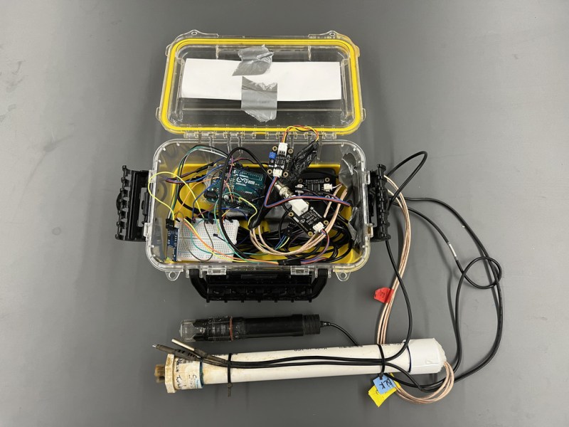
While it can be straightforward to distill water to high purity, this is rarely the best method for producing water for useful purposes. Even drinking water typically needs certain minerals in it, plants may need a certain pH, and wastewater systems have a whole host of other qualities that need to be measured. Measuring water quality is a surprisingly complex endeavor as a result and often involves a wide array of sensors, much like this water quality meter from [RowlesGroupResearch].
The water quality meters that they are putting to use are typically set up in remote locations, without power, and are targeting natural bodies of water and also wastewater treatment plants. Temperature and pH are simple enough to measure and grasp, but this device also includes sensors for total dissolved solids (TDS) and turbidity which are both methods for measuring various amounts and types of particles suspended in the water. The build is based around an Arduino so that it is easy for others to replicate, and is housed in a waterproof box with a large battery, and includes data logging to an SD card in order to make it easy to deploy in remote, outdoor settings and to gather the data at a later time.
The build log for this device also goes into detail about all of the steps needed to set this up from scratch, as well as a comprehensive bill of materials. This could be useful in plenty of professional settings such as community wastewater treatment facilities but also in situations where it’s believed that industrial activity may be impacting a natural body of water. For a water quality meter more focused on drinking water, though, we’d recommend this build that is trained on its own neural network.
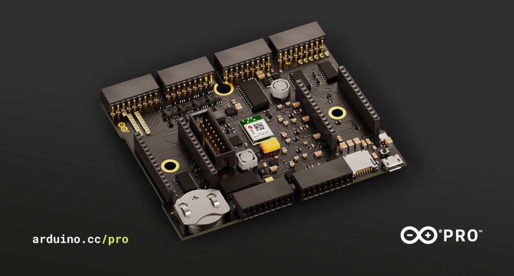
The Arduino Pro lineup continues to grow with the introduction of the new Arduino Edge Control. This is a remote monitoring and control solution optimized for outdoor environments. Easy deployment makes it suitable for smart agriculture, precision farming, and other intelligent control applications in remote locations.
Featuring built-in Bluetooth, Arduino MKR boards can expand connectivity with 2G/3G/CatM1/NB-IoT modems, LoRa®, Sigfox and WiFi. With solar power capabilities you can place it anywhere while leveraging AI on the edge. Once installed in the field, it can then be managed remotely using Arduino IoT Cloud (or other services).
Real-Time Monitoring with Edge Control Sensors
You can also connect sensors, provide real-time monitoring, and drive actuators — commonly used in agriculture — thereby reducing production-related risks.
Particularly aimed at smart agriculture, the sensors can collect real-time data. Weather conditions, soil quality, crop growth and any other data you need. Once sent to Arduino IoT Cloud, the data value chain becomes valuable analytics that support business processes at various levels. For example, crop yield, equipment efficiency, staff performance and so forth. The Edge Control can improve crop quality, reduce effort and minimize error by automating processes like irrigation, fertilization or pest control.
Remote Access and Maintenance
With its robust design, the Edge Control is a fitting solution for applications in any outdoor setting. For example, using it on construction sites or in real estate to automate access control. Similarly, swimming pool maintenance and cleaning companies could monitor and control the condition of pool water from remote locations. As usual, we expect the Arduino community to come up with countless ingenious ways to implement this new technology.
To learn more about how you can use the Edge Control, check out how to get started.
The Edge Control is now available for €169/US$199 on the Arduino Store.
In this tutorial we look at how to use the neat LED Real Time Clock Temperature Sensor Shield for Arduino from PMD Way. That’s a bit of a mouthful, however the shield does offer the following:
four digit, seven-segment LED display
DS1307 real-time clock IC
three buttons
four LEDs
a active buzzer
a light-dependent resistor (LDR)
and a thermistor for measuring ambient temperature
The shield also arrives fully-assembled , so you can just plug it into your Arduino Uno or compatible board. Neat, beginners will love that. So let’s get started, by showing how each function can be used – then some example projects. In no particular order…
The buzzer
A high-pitched active buzzer is connected to digital pin D6 – which can be turned on and off with a simple digitalWrite() function. So let’s do that now, for example:
voidsetup(){// buzzer on digital pin 6pinMode(6,OUTPUT);}// the loop function runs over and over again forevervoidloop(){digitalWrite(6,HIGH);// turn the buzzer on (HIGH is the voltage level)delay(1000);// wait for a seconddigitalWrite(6,LOW);// turn the buzzer off by making the voltage LOWdelay(1000);// wait for a second}
If there is a white sticker over your buzzer, remove it before uploading the sketch. Now for a quick video demonstration. Turn down your volume before playback.
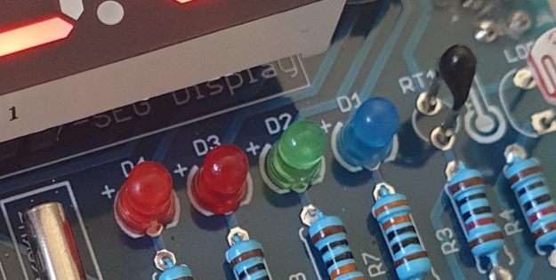
The LEDs
Our shield has four LEDs, as shown below:
They’re labelled D1 through to D4, with D1 on the right-hand side. They are wired to digital outputs D2, D3, D4 and D5 respectively. Again, they can be used with digitalWrite() – so let’s do that now with a quick demonstration of some blinky goodness. Our sketch turns the LEDs on and off in sequential order. You can change the delay by altering the variable x:
voidsetup(){// initialize digital pin LED_BUILTIN as an output.pinMode(2,OUTPUT);// LED 1pinMode(3,OUTPUT);// LED 2pinMode(4,OUTPUT);// LED 3pinMode(5,OUTPUT);// LED 4}intx=200;voidloop(){digitalWrite(2,HIGH);// turn on LED1delay(x);digitalWrite(2,LOW);// turn off LED1. Process repeats for the other three LEDsdigitalWrite(3,HIGH);delay(x);digitalWrite(3,LOW);digitalWrite(4,HIGH);delay(x);digitalWrite(4,LOW);digitalWrite(5,HIGH);delay(x);digitalWrite(5,LOW);}
And in action:
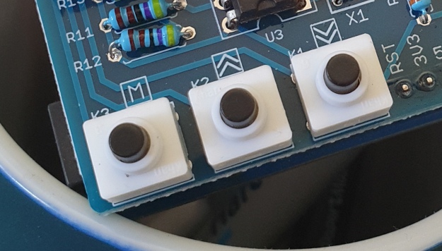
The Buttons
It is now time to pay attention to the three large buttons on the bottom-left of the shield. They look imposing however are just normal buttons, and from right-to-left are connected to digital pins D9, D10 and D11:
They are, however, wired without external pull-up or pull-down resistors so when initialising them in your Arduino sketch you need to activate the digital input’s internal pull-up resistor inside the microcontroller using:
pinMode(pin, INPUT_PULLUP);
Due to this, buttons are by default HIGH when not pressed. So when you press a button, they return LOW. The following sketch demonstrates the use of the buttons by lighting LEDs when pressed:
voidsetup(){// initalise digital pins for LEDs as outputspinMode(2,OUTPUT);// LED 1pinMode(3,OUTPUT);// LED 2pinMode(4,OUTPUT);// LED 3// initalise digital pins for buttons as inputs// and initialise internal pullupspinMode(9,INPUT_PULLUP);// button K1pinMode(10,INPUT_PULLUP);// button K2pinMode(11,INPUT_PULLUP);// button K3}voidloop(){if(digitalRead(9)==LOW){digitalWrite(2,HIGH);delay(10);digitalWrite(2,LOW);}if(digitalRead(10)==LOW){digitalWrite(3,HIGH);delay(10);digitalWrite(3,LOW);}if(digitalRead(11)==LOW){digitalWrite(4,HIGH);delay(10);digitalWrite(4,LOW);}}
You can see these in action via the following video:
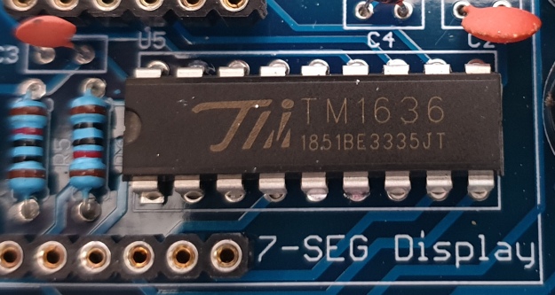
The Numerical LED Display
Our shield has a nice red four-digit, seven-segment LED clock display. We call it a clock display as there are colon LEDs between the second and third digit, just as a digital clock would usually have:
The TM1636 itself is an interesting part, so we’ll explain that in a separate tutorial in the near future. For now, back to the shield.
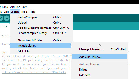
To control the LED display we need to install an Arduino library. In fact the shield needs four, so you can install them all at once now. Download the .zip file from here. Then expand that into your local download directory – it contains four library folders. You can then install them one at a time using the Arduino IDE’s Sketch > Include library > Add .zip library… command:
The supplied library offers five functions used to control the display.
.num(x);
…this displays a positive integer (whole number) between 0 and 9999.
.display(p,d);
… this shows a digit d in location p (locations from left to right are 3, 2, 1, 0)
.time(h,m)
… this is used to display time data (hours, minutes) easily. h is hours, m is minutes
.pointOn();
.pointOff();
… these turn the colon on … and off. And finally:
.clear();
… which clears the display to all off. At the start of the sketch, we need to use the library and initiate the instance of the display by inserting the following lines:
#include <TTSDisplay.h>
TTSDisplay rtcshield;
Don’t panic – the following sketch demonstrates the five functions described above:
#include<TTSDisplay.h>TTSDisplayrtcshield;inta=0;intb=0;voidsetup(){}voidloop(){// display some numbersfor(a=4921;a<5101;a++){rtcshield.num(a);delay(10);}// clear displayrtcshield.clear();// display individual digitsfor(a=3;a>=0;--a){rtcshield.display(a,a);delay(1000);rtcshield.clear();}for(a=3;a>=0;--a){rtcshield.display(a,a);delay(1000);rtcshield.clear();}// turn the colon and offfor(a=0;a<5;a++){rtcshield.pointOn();delay(500);rtcshield.pointOff();delay(500);}// demo the time display functionrtcshield.pointOn();rtcshield.time(11,57);delay(1000);rtcshield.time(11,58);delay(1000);rtcshield.time(11,59);delay(1000);rtcshield.time(12,00);delay(1000);}
And you can see it in action through the video below:
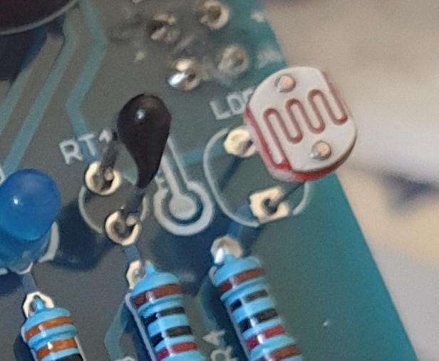
The LDR (Light Dependent Resistor)
LDRs are useful for giving basic light level measurements, and our shield has one connected to analog input pin A1. It’s the two-legged item with the squiggle on top as shown below:
The resistance of LDRs change with light levels – the greater the light, the less the resistance. Thus by measuring the voltage of a current through the LDR with an analog input pin – you can get a numerical value proportional to the ambient light level. And that’s just what the following sketch does:
#include<TTSDisplay.h>TTSDisplayrtcshield;inta=0;voidsetup(){}voidloop(){// read value of analog inputa=analogRead(A1);// show value on displayrtcshield.num(a);delay(100);}
The Thermistor
A thermistor is a resistor whose resistance is relative to the ambient temperature. As the temperature increases, their resistance decreases. It’s the black part to the left of the LDR in the image below:
We can use this relationship between temperature and resistance to determine the ambient temperature. To keep things simple we won’t go into the theory – instead, just show you how to get a reading.
The thermistor circuit on our shield has the output connected to analog input zero, and we can use the library installed earlier to take care of the mathematics. Which just leaves us with the functions.
At the start of the sketch, we need to use the library and initiate the instance of the thermistor by inserting the following lines:
#include <TTSTemp.h>
TTSTemp temp;
… then use the following which returns a positive integer containing the temperature (so no freezing cold environments):
.get();
For our example, we’ll get the temperature and show it on the numerical display:
And our thermometer in action. No video this time… a nice 24 degrees C in the office:
The Real-Time Clock
Our shield is fitted with a DS1307 real-time clock IC circuit and backup battery holder. If you insert a CR1220 battery, the RTC will remember the settings even if you remove the shield from the Arduino or if there’s a power blackout, board reset etc:
The DS1307 is incredibly popular and used in many projects and found on many inexpensive breakout boards. We have a separate tutorial on how to use the DS1307, so instead of repeating ourselves – please visit our specific DS1307 Arduino tutorial, then return when finished.
Where to from here?
We can image there are many practical uses for this shield, which will not only improve your Arduino coding skills but also have some useful applications. An example is given below, that you can use for learning or fun.
Temperature Alarm
This projects turns the shield into a temperature monitor – you can select a lower and upper temperature, and if the temperature goes outside that range the buzzer can sound until you press it.
Here’s the sketch:
#include<TTSDisplay.h>#include<TTSTemp.h>TTSTemptemp;TTSDisplayrtcshield;booleanalarmOnOff=false;inthighTemp=40;intlowTemp=10;intcurrentTemp;voidLEDsoff(){// function to turn all alarm high/low LEDs offdigitalWrite(2,LOW);digitalWrite(4,LOW);}voidsetup(){// initalise digital pins for LEDs and buzzer as outputspinMode(2,OUTPUT);// LED 1pinMode(3,OUTPUT);// LED 2pinMode(4,OUTPUT);// LED 3pinMode(5,OUTPUT);// LED 4pinMode(6,OUTPUT);// buzzer// initalise digital pins for buttons as inputs// and initialise internal pullupspinMode(9,INPUT_PULLUP);// button K1pinMode(10,INPUT_PULLUP);// button K2pinMode(11,INPUT_PULLUP);// button K3}voidloop(){// get current temperaturecurrentTemp=temp.get();// if current temperature is within set limts// show temperature on displayif(currentTemp>=lowTemp||currentTemp<=highTemp)// if ambient temperature is less than high boundary// OR if ambient temperature is grater than low boundary// all is well{LEDsoff();// turn off LEDsrtcshield.num(currentTemp);}// if current temperature is above set high bounday, show red LED and// show temperature on display// turn on buzzer if alarm is set to on (button K3)if(currentTemp>highTemp){LEDsoff();// turn off LEDsdigitalWrite(4,HIGH);// turn on red LEDrtcshield.num(currentTemp);if(alarmOnOff==true){digitalWrite(6,HIGH);// buzzer on }}}// if current temperature is below set lower boundary, show blue LED and// show temperature on display// turn on buzzer if alarm is set to on (button K3)if(currentTemp<lowTemp){LEDsoff();// turn off LEDsdigitalWrite(2,HIGH);// turn on blue LEDrtcshield.num(currentTemp);if(alarmOnOff==true){digitalWrite(6,HIGH);// buzzer on }}}// --------turn alarm on or off-----------------------------------------------------if(digitalRead(11)==LOW)// turn alarm on or off{alarmOnOff=!alarmOnOff;if(alarmOnOff==0){digitalWrite(6,LOW);// turn off buzzerdigitalWrite(5,LOW);// turn off alarm on LED}// if alarm is set to on, turn LED on to indicate thisif(alarmOnOff==1){digitalWrite(5,HIGH);}delay(300);// software debounce}// --------set low temperature------------------------------------------------------if(digitalRead(10)==LOW)// set low temperature. If temp falls below this value, activate alarm{// clear display and turn on blue LED to indicate user is setting lower boundaryrtcshield.clear();digitalWrite(2,HIGH);// turn on blue LEDrtcshield.num(lowTemp);// user can press buttons K2 and K1 to decrease/increase lower boundary.// once user presses button K3, lower boundary is locked in and unit goes// back to normal statewhile(digitalRead(11)!=LOW)// repeat the following code until the user presses button K3{if(digitalRead(10)==LOW)// if button K2 pressed{--lowTemp;// subtract one from lower boundary// display new value. If this falls below zero, won't display. You can add checks for this yourself :)rtcshield.num(lowTemp);}if(digitalRead(9)==LOW)// if button K3 pressed{lowTemp++;// add one to lower boundary// display new value. If this exceeds 9999, won't display. You can add checks for this yourself :)rtcshield.num(lowTemp);}delay(300);// for switch debounce}digitalWrite(2,LOW);// turn off blue LED}// --------set high temperature-----------------------------------------------------if(digitalRead(9)==LOW)// set high temperature. If temp exceeds this value, activate alarm{// clear display and turn on red LED to indicate user is setting lower boundaryrtcshield.clear();digitalWrite(4,HIGH);// turn on red LEDrtcshield.num(highTemp);// user can press buttons K2 and K1 to decrease/increase upper boundary.// once user presses button K3, upper boundary is locked in and unit goes// back to normal statewhile(digitalRead(11)!=LOW)// repeat the following code until the user presses button K3{if(digitalRead(10)==LOW)// if button K2 pressed{--highTemp;// subtract one from upper boundary// display new value. If this falls below zero, won't display. You can add checks for this yourself :)rtcshield.num(highTemp);}if(digitalRead(9)==LOW)// if button K3 pressed{highTemp++;// add one to upper boundary// display new value. If this exceeds 9999, won't display. You can add checks for this yourself :)rtcshield.num(highTemp);}delay(300);// for switch debounce}digitalWrite(4,LOW);// turn off red LED}}
Operating instructions:
To set lower temperature, – press button K2. Blue LED turns on. Use buttons K2 and K1 to select temperature, then press K3 to lock it in. Blue LED turns off.
To set upper temperature – press button K1. Red LED turns on. Use buttons K2 and K1 to select temperature, then press K3 to lock it in. Red LED turns off.
If temperature drops below lower or exceeds upper temperature, the blue or red LED will come on.
You can have the buzzer sound when the alarm activates – to do this, press K3. When the buzzer mode is on, LED D4 will be on. You can turn buzzer off after it activates by pressing K3.
Display will show ambient temperature during normal operation.
You can see this in action via the video below:
Conclusion
This is a fun and useful shield – especially for beginners. It offers a lot of fun and options without any difficult coding or soldering – it’s easy to find success with the shield and increase your motivation to learn more and make more.
You can be serious with a clock, or annoy people with the buzzer. And at the time of writing you can have one for US$14.95, delivered. So go forth and create something.
A little research has shown that this shield was based from a product by Seeed, who discontinued it from sale. I’d like to thank them for the library.
This post brought to you by pmdway.com – everything for makers and electronics enthusiasts, with free delivery worldwide.
To keep up to date with new posts at tronixstuff.com, please subscribe to the mailing list in the box on the right, or follow us on twitter @tronixstuff.
Reading the temperature of your environment is pretty easy right? A quick search suggests the utterly ubiquitous DHT11, which speaks a well documented protocol and has libraries for every conceivable microcontroller and platform. Plug that into your Arduino and boom, temperature (and humidity!) readings. But the simple solution doesn’t hit every need, sometimes things need to get more esoteric.
The technique summarized by an image from Microchip Appnote AN685
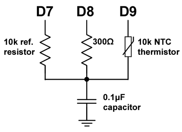
For years we’ve been watching [Edward]’s heroic efforts to build accessible underwater sensing hardware. When we last heard from him he was working on improving the accuracy of his Arduino’s measurements of the humble NTC thermistor. Now the goal is the same but he has an even more surprising plan, throw the ADC out entirely and sample an analog thermistor using digital IO. It’s actually a pretty simple trick based on an intuitive observation, that microcontrollers are better at measuring time than voltage.
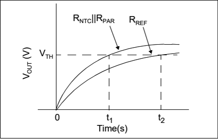
The basic circuit
The circuit has a minimum of four components: a reference resistor, the thermistor, and a small capacitor with discharge resistor. To sense you configure a timer to count, and an edge interrupt to capture the value in the timer when its input toggles. One sensing cycle consists of discharging the cap through the discharge resistor, enabling the timer and interrupt, then charging it through the value to measure. The value captured from the timer will be correlated to how long it took the cap to charge above the logic-high threshold when the interrupt triggers. By comparing the time to charge through the reference against the time to charge through the thermistor you can calculate their relative resistance. And by performing a few calibration cycles at different temperatures ([Edward] suggests at least 10 degrees apart) you can anchor the measurement system to real temperature.
[Edward], creator of the Cave Pearl project, an underwater data logger, needed a way to measure temperature with a microcontroller. Normally, this problem is most easily solved by throwing a temperature sensor on the I2C bus — these sensors are cheap and readily available. This isn’t about connecting a temperature sensor in your Arduino. This build is about using the temperature sensor in your clock.
The ATMega328p, the chip at the heart of all your Arduino Uno clones, has within it a watchdog timer that clicks over at a rate of 110 kHz. This watchdog timer is somewhat sensitive to temperature, and by measuring this temperature sensor you can get some idea of the temperature of the epoxy blob that is a modern microcontroller. The trick is calibrating the watchdog timer, which was done with a homemade ‘calibration box’ in a freezer consisting of two very heavy ceramic pots with a bag of rice between them to add thermal mass (you can’t do this with water because you’re putting it in a freezer and antique crocks are somewhat valuable).
By repeatedly taking the microcontroller through a couple of freeze-thaw cycles, [Edward] was able to calibrate this watchdog timer to a resolution of about 0.0025°C, which is more than enough for just about any sensor application. Discussions of accuracy and precision notwithstanding, it’s pretty good.
This technique measures the temperature of the microcontroller with an accuracy of 0.005°C or better, and it’s using it with just the interrupt timer. That’s not to say this is the only way to measure the temperature of an ATMega; some of these chips have temperature sensors built right into them, and we’ve seen projects that use this before. However, this documented feature that’s clearly in the datasheet seems not to be used by many people.
Gardening is a rewarding endeavour, and easily automated for the maker with a green thumb. With simplicity at its focus, Hackaday.io user [MEGA DAS] has whipped up a automated planter to provide the things plants crave: water, air, and light.
[MEGA DAS] is using a TE215 moisture sensor to keep an eye on how thirsty the plant may be, a DHT11 temperature and humidity sensor to check the airflow around the plant, and a BH1750FVI light sensor for its obvious purpose. To deliver on these needs, a 12V DC water pump and a small reservoir will keep things right as rain, a pair of 12V DC fans mimic a gentle breeze, and a row of white LEDs supplement natural light when required.
The custom board is an Arduino Nano platform, with an ESP01 to enable WiFi capacity and a Bluetooth module to monitor the plant’s status while at home or away. Voltage regulators, MOSFETs, resistors, capacitors, fuses — can’t be too careful — screw header connectors, and a few other assorted parts round out the circuit. The planter is made of laser cut pieces with plenty of space to mount the various components and hide away the rest. You can check out [MEGA DAS]’ tutorial video after the break!
[MEGA DAS] has made his Arduino code and phone app available to download for anyone else wanting to build their own. Once assembled, he can ensure his plant is well taken care of wherever he is with a few taps on his phone. Not too shabby for a seven day build.
We didn’t include a “Most Ornate” category in this year’s Coin Cell Challenge, but if we had, the environmentally reactive jewelry created by [Maxim Krentovskiy] would certainly be the one to beat. Combining traditional jewelry materials with an Arduino-compatible microcontroller, RGB LEDs, and environmental sensors; the pieces are able to glow and change color based on environmental factors. Sort of like a “mood ring” for the microcontroller generation.
[Maxim] originally looked for a turn-key solution for his reactive jewelry project, but found that everything out there wasn’t quite what he was looking for. It was all either too big or too complicated. His list of requirements was relatively short and existing MCU boards were simply designed for more than what he needed.
On his 30 x 30 mm PCB [Maxim] has included the bare essentials to get an environmentally aware wearable up and running. Alongside the ATtiny85 MCU is a handful of RGB LEDs (with expansion capability to add more), as well as analog light and temperature sensors. With data from the sensors, the ATtiny85 can come up with different colors and blink frequencies for the LEDs, ranging from a randomized light show to a useful interpretation of the local environment.
It’s not much of a stretch to imagine practical applications for this technology. Consider a bracelet that starts flashing red when the wearer’s body temperature gets too high. Making assistive technology visually appealing is always a challenge, and there’s undoubtedly a market for pieces of jewelry that can communicate a person’s physical condition even when they themselves may be unable to.
Whether you’re lodged in an apartment with a poor view of the sky like [Becky Stern] or are looking for an at-a-glance report of the current weather, you might consider this minimalist weather display instead of checking your computer or your phone every time you’re headed out the door.
The first order of business was to set up her Feather Huzzah ESP8266 module. [Becky] started with a blink test to ensure it was working properly. Once that was out of the way, she moved on to installing a few libraries. Temperature data fetched by an IFTTT feed is displayed on a seven-segment display, while additional feeds separately retrieve information for each basic weather type: sunny, overcast, rain, snow.
All it took to create the sleek display effect was a few pieces of cardboard inside a shadow box frame, a sheet of paper as a diffuser, and twelve Neopixel RGB LEDs hidden inside. Trimming and securing everything in place as well as notching out the back of the frame for the power cable finished the assembly. Check out the build video after the break.
You'd think there'd be something like a dual set point thermostat on the market already, but it doesn't look like there is. Guess you'll just have to make one.
You'd think there'd be something like a dual set point thermostat on the market already, but it doesn't look like there is. Guess you'll just have to make one.
Planet Arduino is, or at the moment is wishing to become, an aggregation of public weblogs from around the world written by people who develop, play, think on Arduino platform and his son. The opinions expressed in those weblogs and hence this aggregation are those of the original authors. Entries on this page are owned by their authors. We do not edit, endorse or vouch for the contents of individual posts. For more information about Arduino please visit www.arduino.cc
You are currently browsing the archives for the temperature category.


