Posts | Comments

Planet Arduino

Archive for the ‘ATTINY85’ Category

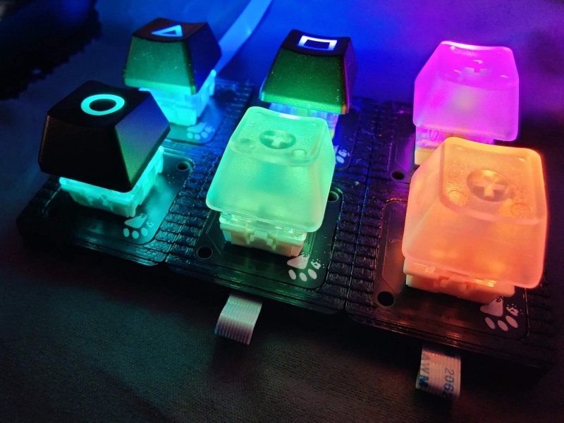
[Gili Yankovitch] has always wanted some kind of macro keypad for all those boss-slaying combos he keeps up the sleeve of his wizard robe while playing WoW. Seventeen years later, he finally threw down the gauntlet and built one. But really, this is an understatement, because Paws is kind of the customizable macropad to end all customizable macropads.

This thing is completely bespoke, and yet cookie cutter at the same time — but we mean that in the best possible way. Paws can be made in any shape or form, and quite easily. How is this even possible, you ask? Well, every single key has its own microcontroller.

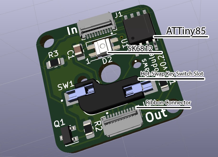
Yep, each key has an ATtiny85 and a cute little ribbon cable, and these form a token ring network that talks to an Arduino, which provides the keyboard interface to the computer. To make things even easier, [Gili] built a simple programming UI that automatically recognizes the configuration and number of keys, and lets the user choose the most important bit of all — the color of the LED.

[Gili] wanted to combine all the skills he’s learned since the worst timeline started in early 2020 — embedded software, CAD, electronics, and PCB design. We’d like to add networking to that list, especially since he figured out a nice workaround for the slowness of I²C and the limitations of communication between the ‘tiny85s and the Arduino. Though [Gili] may have started out with a tall order, he definitely filled it. Want to get your paws on the design files? Just claw your way over to GitHub.

If your customization interests lie more toward what program is in focus, be sure to check out Keybon, which was one of the many awesome winners of our Odd Inputs and Peculiar Peripherals contest.

You would think the hard part about creating a spectrum analyzer using a pint-sized ATTiny85 would be the software. But for [tuenhidiy], we suspect the hard part was fabricating an array of 320 LEDs that the little processor can drive. The design does work though, as you can see in the video below.

The key is to use a TPIC6B595N which is an 8-bit shift register made to drive non-logic outputs. With all outputs on, the driving FETs can supply 150 mA per channel and the device can handle 500 mA per channel peak. At room temperature, the part can go over 1W of total power dissipation, although that goes down with temperature, of course. If you need higher power, there’s a DW-variant of the part that can handle a few hundred milliwatts more.

A fixed-point FFT library does the actual work. The program simply reads samples, processes the FFT, and drives the LEDs through the shift registers.

The construction technique is also a bit interesting as much of the wiring is left over LED leads. We admire the neat work, but we think we’d have had better luck with PCB traces.

Although billed as a spectrum analyzer, a device like this is really more of a music visualizer. If you want a real spectrum analyzer, they have become reasonably cheap. As impractical as the LED grid is for practical output, it beats ping pong balls.

400

Portable air conditioning units are a great way to cool off a space during the hot summer months, but they require some place to blow the heat they’ve removed from your room. [VincentMakes] got a portable AC unit for his home, but he found that the place he wanted to put it was too far from the only window he could use to dump the hot air. Having too long of a duct on the hot air exhaust increases the back pressure on the fan which could cause it to prematurely fail, so [Vincent] used an extractor fan to automatically give is AC unit’s exhaust a boost on its way to the window.

Because his AC can operate at low, medium, and high speeds, he chose an extractor fan that also supported multiple speeds and took care to match the airflow of the AC and extractor fan to avoid putting too much strain on either fan. He designed a system to automatically set the speed of the boosting fan to match that of the AC using a Hall effect current sensor to measure the AC unit’s power draw and an Arduino Nano for control. A custom PCB interfaces the Nano to the Hall Sensor and control relays, and we have to applaud [Vincent] for keeping the +5V DC and 230V AC far, far away from each other. In addition to this fine electronics work, [Vincent] also built an enclosure for the fan controller that allows the fan to be mounted on top at an angle, which helps avoid having hard bends in the exhaust duct.

If this has you thinking about smart air conditioners to keep cool this summer, check out this ESP8266-powered smart AC system, or this Raspberry Pi-based system that controls both AC and blinds!

As every Hackaday reader knows, and tells us at every opportunity in the comments, adding an Arduino to your project instantly makes it twice as cool. But what if, in the course of adding an Arduino to your project, you run into a problem and need to debug the code? What if you could use a second Arduino to debug the first? That would bring your project up to two Arduinos, instantly making it four times as awesome as before you started! Who could say no to such exponential gains?

Debugging an ATTiny85

Not [Wayne Holder], that’s for sure. He writes in to let us know about a project he’s been working on for a while that allows you to debug the execution of code on an Arduino with a second Arduino. In fact, the target chip could even be another AVR series microcontroller such as a the ATTiny85. With his software you can single-step through the code, view and modify values in memory, set breakpoints, and even disassemble the code. Not everything is working fully yet, but what he has so far is very impressive.

The trick is exploiting a feature known as “debugWIRE” that’s included in many AVR microcontrollers. Unfortunately documentation on this feature is hard to come by, but with some work [Wayne] has managed to figure out how most of it works and create an Arduino Sketch that lets the user interact with the target chip using a simple menu system over the serial monitor, similar to the Bus Pirate.

[Wayne] goes into plenty of detail on his site and in the video included after the break, showing many of the functions he’s got working so far in his software against an ATTiny85. If you spend a lot of time working on AVR projects, this looks like something you might want to keep installed on an Arduino in your tool bag for the future.

Debugging microcontroller projects can be a huge time saver when your code starts running on real hardware, but often takes some hacking to get working.

We didn’t include a “Most Ornate” category in this year’s Coin Cell Challenge, but if we had, the environmentally reactive jewelry created by [Maxim Krentovskiy] would certainly be the one to beat. Combining traditional jewelry materials with an Arduino-compatible microcontroller, RGB LEDs, and environmental sensors; the pieces are able to glow and change color based on environmental factors. Sort of like a “mood ring” for the microcontroller generation.

[Maxim] originally looked for a turn-key solution for his reactive jewelry project, but found that everything out there wasn’t quite what he was looking for. It was all either too big or too complicated. His list of requirements was relatively short and existing MCU boards were simply designed for more than what he needed.

On his 30 x 30 mm PCB [Maxim] has included the bare essentials to get an environmentally aware wearable up and running. Alongside the ATtiny85 MCU is a handful of RGB LEDs (with expansion capability to add more), as well as analog light and temperature sensors. With data from the sensors, the ATtiny85 can come up with different colors and blink frequencies for the LEDs, ranging from a randomized light show to a useful interpretation of the local environment.

It’s not much of a stretch to imagine practical applications for this technology. Consider a bracelet that starts flashing red when the wearer’s body temperature gets too high. Making assistive technology visually appealing is always a challenge, and there’s undoubtedly a market for pieces of jewelry that can communicate a person’s physical condition even when they themselves may be unable to.

Form or function, life saving or complete novelty, there’s still time to enter your own project in the 2017 Coin Cell Challenge.


Filed under: Arduino Hacks, ATtiny Hacks, contests, Wearable Hacks

[Corey Harding] designed his business card as a USB-connectable demonstration of his skill. If potential manager inserts the card in a USB drive, open a text editor, then touches the copper pad on the PCB, [Corey]’s contact info pops up in the text box.

In addition to working as a business card, the PCB also works as a Tiny 85 development board, with a prototyping area for adding sensors and other components, and with additional capabilities broken out: you can add an LED, and there’s also room for a 1K resistor, a reset button, or break out the USB’s 5V for other uses. There’s an AVR ISP breakout for reflashing the chip.

Coolly, [Corey] intended for the card to be an Open Source resource for other people to make their own cards, and he’s providing the Fritzing files for the PCB. Fritzing is a great program for beginning and experienced hardware hackers to lay out quick and dirty circuits, make wiring diagrams, and even export PCB designs for fabrication. You can download [Corey]’s files from his GitHub repository.

For another business card project check out this full color business card we published last month.


Filed under: Arduino Hacks

[Captain Credible] is a chiptune music artist. He wanted to release an EP, but a regular old em-pee-three was too lame for him, so he made a tiny board with a coin cell, an ATtiny85, and a 3.5mm socket on it.

Rather than just writing some code to generate the tones for a pre-composed song, his “Dead Cats” EP generates the music itself. Using the arduino-tiny library, which adds the tone() function to the ATtiny, he has the chip pick its own time signature, key, subdivisions, and tempo. The melody and drum beat is randomly generated into an array. In addition to that, there are some code “one-liners” which insert unique sounds. After that the code just loops through the music.

If you don’t like the song, simply unplug the audio cable and plug it back in. The 3.5mm jack he chose has a built-in micro-switch, so the board is only powered up if someone is listening. If you’d like to see the circuit diagram, purchase the EP, or take a look at the code, all of that is available on his site.


Filed under: Arduino Hacks, musical hacks

Chromecasts are fantastic little products, they’re basically little HDMI sticks you can plug into any monitor or TV, and then stream content using your phone or computer as the controller. They are powered by a micro USB port in the back, and if you’re lucky, your TV has a port you can suck the juice off. But what if you want to turn it off while you use a different input on your TV? You might have to build a power switch.

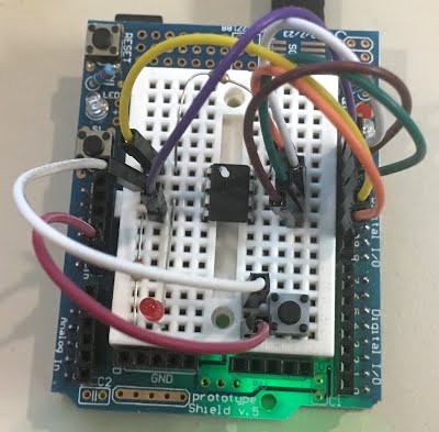
Now in all honesty, the Chromecast gets hot but the amount of power it draws when not in use is still pretty negligible compared to the draw of your TV. Every watt counts, and [Ilias] took this as an opportunity to refine his skills and combine a system using an Arduino, Bluetooth, and Android to create a robust power switch solution for the Chromecast.

The setup is rather simple. An HC-05 Bluetooth module is connected to an Attiny85, with some transistors to control a 5V power output. The Arduino takes care of a bluetooth connection and uses a serial input to control the transistor output. Finally, this is all controlled by a Tasker plugin on the Android phone, which sends serial messages via Bluetooth.

All the information you’ll need to make one yourself is available at [Ilias’] GitHub repository. For more information on the Chromecast, why not check out our review from almost three years ago — it’s getting old!


Filed under: Android Hacks, Arduino Hacks, home entertainment hacks
Oct
23

Now Let’s See The World’s Largest Arduino

arduino, arduino hacks, attiny, ATtiny Hacks, ATTINY85, smallest arduino Comments Off on Now Let’s See The World’s Largest Arduino 

atomsoft

A few days ago we saw what would have been a killer Kickstarter a few years ago. It was the smallest conceivable ATtiny85 microcontroller board, with resistors, diodes, a USB connector, and eight pins for plugging into a breadboard. It’s a shame this design wasn’t around for the great Arduino Minification of Kickstarter in late 2011; it would have easily netted a few hundred thousand dollars, a TED talk, and a TechCrunch biopic.

[AtomSoftTech] has thrown his gauntlet down and created an even smaller ‘tiny85 board. it measures 0.4in by 0.3in, including the passives, reset switch, and USB connector. To put that in perspective, the PDIP package of the ‘tiny85 measures 0.4 x 0.4. How is [Atom] getting away with this? Cheating, splitting the circuit onto two stacked boards, or knowing the right components, depending on how you look at it.

USB 
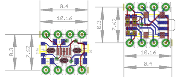
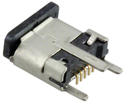
[Atom] is using a few interesting components in this build. The USB connector is a surface mount vertical part, making the USB cord stick out the top of this uC board. The reset button is extremely small as well, sticking out of the interior layer of the PCB sandwich.

[AtomSoft] has the project up on OSH Park ($1.55 for three. How cool is that?), and we assume he’ll be selling the official World’s Smallest Arduino-compatible board at Tindie in time.


Filed under: Arduino Hacks, ATtiny Hacks
Oct
10

The Arduino Gemma

arduino, Arduino Gemma, ATTINY85, USB Comments Off on The Arduino Gemma 

ArduinoGemma

by elektor.com:

In a presentation at the Maker Faire held in Rome this weekend Arduino co-founder Massimo Banzi gave a preview of the soon to be released Gemma wearable Arduino board. The 27 mm diameter board contains an ATtiny85 processor programmable from the Arduino IDE via Gemma’s micro USB connector. The design is a collaborative effort together with Adafruit Industries who also worked on the Arduino Micro.

The ATtiny85 has 8K of flash and 5 I/O pins, including analog inputs and PWM outputs. It was designed with a USB bootloader so you can plug it into any computer and reprogram it over a USB port (it uses 2 of the 5 I/O pins, leaving you with 3). Ideal for small & simple projects sewn with conductive thread, the Arduino Gemma fits the needs of most of entry-level wearable creations including reading sensors and driving addressable LED pixels.

The Arduino Gemma - [Link]


  • Newsletter

    Sign up for the PlanetArduino Newsletter, which delivers the most popular articles via e-mail to your inbox every week. Just fill in the information below and submit.

  • Like Us on Facebook