Posts | Comments

Planet Arduino

Archive for the ‘reverse engineering’ Category

IR Remote tester in use, showing a remote control lighting up an LED and screenshots of the Arduino serial terminal

Even though some devices now use WiFi and Bluetooth, so much of our home entertainment equipment still relies on its own proprietary infrared remote control. By and large (when you can find them) they work fine, but what happens when they stop working?  First port of call is to change the batteries, of course, but once you’ve tried that what do you do next? [Hulk] has your back with this simple but effective IR Remote Tester / Decoder.

IR remote tester schematic showing arduino, receiver, LED and resistor
How to connect the TSOP4838 to an Arduino to read the transmitted codes

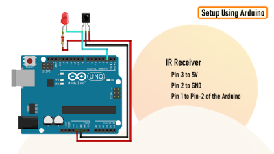
By using a cheap integrated IR receiver/decoder device (the venerable TSOP4838), most of the hard work is done for you! For a quick visual check that your remote is sending codes, it can easily drive a visible LED with just a resistor for a current-limit, and a capacitor to make the flickering easier to see.

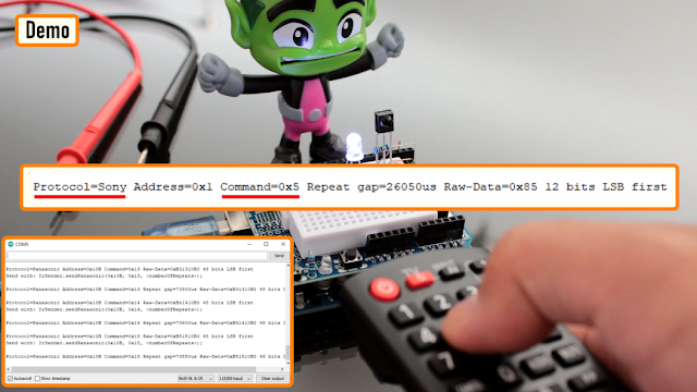
For an encore, [Hulk] shows how to connect this up to an Arduino and how to use the “IRremote” library to see the actual data being transmitted when the buttons are pressed.

It’s not much of a leap to imagine what else you might be able to do with this information once you’ve received it – controlling your own projects, cloning the IR remote codes, automating remote control sequences etc..

It’s a great way to make the invisible visible and add some helpful debug information into the mix.

We recently covered a more complex IR cloner, and if you need  to put together a truly universal remote control, then this project may be just what you need.

Working with vintage computer technology can feel a bit like the digital equivalent of archeology. Documentation is often limited or altogether absent today — if it was ever even public in the first place. So you end up reverse engineering a device’s functionality through meticulous inspection and analysis. Spencer Nelson has a vintage NeXT keyboard from the ’80s and wanted to get it working with modern computers via USB. To make that happen, he reverse engineered the protocol and used an Arduino as an adapter.

NeXT was a computer company founded by Steve Jobs in the ’80s, in the period after he left Apple. A little over ten years later, Apple bought NeXT and Jobs rejoined the company. NeXT only released a few computers, but they are noteworthy and desirable to collectors. This particular keyboard is from 1988 and worked with the first generation NeXT Computer. Unlike modern keyboards that share the USB protocol, keyboards from this era utilized proprietary protocols. This particular model had an enigmatic protocol that Nelson became obsessed with deciphering.

Nelson started with an Arduino Micro with the intention of using an existing library. But that resulted in unpredictable and jumbled text. After inspecting the keyboard’s output signal with both an oscilloscope and a logic analyzer, Nelson determined that the keyboard protocol worked at an unusual 52.74 microsecond pulse width that the library didn’t account for. It turns out that that was the result of NeXT using a cheap 455 kHz resonator intended for AM radios. Every 24 ticks of that resonator, it would send a data bit (18,958 hertz equals once pulse every 52.74 microseconds).

With this information in hand, Nelson was able to create his own Arduino sketch to analyze the signal coming from the NeXT keyboard. It can output the text via the serial console, but it is also possible to configure an Arduino as a USB HID to output the text to any modern computer.

The post Reverse engineering an ’80s NeXT keyboard appeared first on Arduino Blog.

Recently [Imran Haque]’s family bought the quite popular Peloton bike. After his initial skepticism melted to a quiet enthusiasm, [Imran] felt his hacker curiosity begin to probe the head unit on the bike. Which despite being a lightly skinned android tablet, has a reputation for being rather locked down. The Peloton bike will happily collect data such as heart rate from other devices but is rather reticent to broadcast any data it generates such as cadence and power. [Imran] set out to decode and liberate the Peleton’s data by creating a device he has dubbed PeloMon. He credits the inspiration for his journey to another hacker who connected a Raspberry Pi to their bricked exercise bike.

As a first step, [Imran] step began with decoding the TRRS connector that connects the bike to the head unit. With the help of a multi-meter and a logic analyzer, two 19200bps 8N1 RS-323 channels (TX and RX) were identified. Once the basic transport layer was established, he next set to work decoding the packets. By plotting the bytes in the packets and applying deductive reasoning, a rough spec was defined. The head unit requested updates every 100ms and the bike responded with cadence, power, and resistance data depending on the request type (the head unit did a round-robin through the three data types).

Once the protocol was decoded, the next step for [Imran] was to code up an emulator. It seems a strange decision to write an emulator for a device with a simple protocol, but the reasoning is quite sound. It avoids a 20-minute bike ride every time a code change needs to be tested. [Imran] wrote both an event-driven and a timing-accurate emulator. The former runs on the same board as the PeloMon and the latter runs on a separate board (an Arduino).

The hardware chosen for the PeloMon was an Adafruit Feather 32u4 Bluefruit LE. It was chosen for supporting Bluetooth LE as well as having onboard EEPROM. A level shifter allows the microcontroller to talk directly to the RS-323 on the bike. After a few pull requests to the Adafruit Bluetooth libraries and a fair bit of head-banging, [Imran] has code that advertises two Bluetooth services, one for speed and another for power. A Bluetooth serial console is also included for debugging without having to pull the circuit out.

The code, schematics, emulators, and research notes are all available on GitHub.

The Samsung PS-WTX500 subwoofer is designed to be used as part of a 5.1 channel home theater system, but not just any system. It contains the amplifiers for all the channels, but they’ll only function when the subwoofer is connected to the matching receiver. [Alejandro Zarate] figured there must be some way to unlock the system’s full functionality without being limited to the original receiver, he just needed to reverse engineer how the subwoofer worked.

All the wires tuck underneath the Arduino

The result is a fantastically well documented write-up that covers the whole process, starting with how [Alejandro] identified and researched the Pulsus PS9829B Digital Audio Processor (DAP). Documentation for this particular chip seems hard to come by, but he was able to find a similar chip from the same manufacturer that was close enough to put him on the right track. From there, he started studying the SPI communications between the DAP and the subwoofer’s S3P70F4 microcontroller.

After analyzing the communication between the two chips, [Alejandro] pulled the S3P70F4 off the board and wired an Arduino Pro Mini 328 in its place. The Arduino was quite a bit larger than the original microcontroller, but with some careful wiring, he manged a very professional looking installation. Short of coming up with a custom PCB adapter, we don’t think it could look much better.

With some relatively straightforward code and a listing of the captured byte sequences, the Arduino was able to power up the PS-WTX500’s amplifiers and handle the incoming audio signal as a stand-alone device.

In the past we’ve seen a similar trick done with the ESP8266, which had the added benefit of enabling WiFi control of the speakers. We’re all for adding modern functionality to older hardware, even if you’ve got to hang it off the back as an external module.

[James Tate] is starting up a project to make a “Super Reverse-Engineering Tool”. First on his list? A simple NAND flash reader, for exactly the same reason that Willie Sutton robbed banks: because that’s where the binaries are.

As it stands, [James]’s first version of this tool is probably not what you want to use if you’re dumping a lot of NAND flash modules. His Arduino code reads the NAND using the notoriously slow digital_read() and digital_write() commands and then dumps it over the serial port at 115,200 baud. We’re not sure which is the binding constraint, but neither of these methods are built for speed.

Instead, the code is built for hackability. It’s pretty modular, and if you’ve got a NAND flash that needs other low-level bit twiddling to give up its data, you should be able to get something up and working quickly, start it running, and then go have a coffee for a few days. When you come back, the data will be dumped and you will have only invested a few minutes of human time in the project.

With TSOP breakout boards selling for cheap, all that prevents you from reading out the sweet memory contents of a random device is a few bucks and some patience. If you haven’t ever done so, pull something out of your junk bin and give it a shot! If you’re feeling DIY, or need to read a flash in place, check out this crazy solder-on hack. Or if you can spring for an FTDI FT2233H breakout board, you can read a NAND flash fast using essentially the same techniques as those presented here.


Filed under: Arduino Hacks, hardware
Feb
25

An electronic diesel engine controlled with Arduino Mega

arduino, arduino mega, Cars, diesel, Engine, mega, reverse engineering Commenti disabilitati su An electronic diesel engine controlled with Arduino Mega 

Diesel_Engine

A few years ago Sven and Juho started working on the same type of project without knowing about each other and only by a coincidence their paths crossed. They wrote me about their cool story and the successful experiment of upgrading a diesel engine using Arduino Mega:

There’s a prettty large community out there in the car/motorsports hobbyist world that loves their vehicle but the engine is getting old, worn out and maybe even too bad to renovate. What people do is to take the engine from a newer car with a modern direct injected diesel engine, with all the cables, sensors and motor controller (the ECU) and adapt it to their beloved old car. This is exactly what is going on with the VW buses (called vanagons in the US) where the diesel engines from the beginning is a bit on the small side and 20 years later their performance is not much better than a garden tractor. A “new” electronically controlled engine is used to replace the old worn out engine, and with that follows better power, less pollution and way better fuel economy.

Schematic_diesel

BUT, this takes time and is a complex project. You have to adapt the cablage, install the ECU (the motor controller) and must be sure that all the peripheral sensors sitting all around the engine is brought over to the new car and is working. You might also have to adapt the instrument cluster behind the steering wheel to make all the warning lights and gauges to work again.

The idea with the Arduino controller is to take the ENGINE ONLY and then let the Arduino manage the engine with the sensors that is on the engine itself. By doing this, the motor swap is reduced to a weekend project and everything in the bus is working as it was before. No instruments modification, no need for external valves and sensors, no adapted cablage. Just the Arduino.

You can find the whole documentations and the details of the project on Juho’s website.

ardAndRFoutlets

Cyber Monday may be behind us, but there are always some hackable, inexpensive electronics to be had. [Stephen's] wireless Android/Arduino outlet hack may be the perfect holiday project on the cheap, especially considering you can once again snag the right remote controlled outlets from Home Depot. This project is similar to other remote control outlet builds we’ve seen here, but for around $6 per outlet: a tough price to beat.

[Stephen] Frankenstein’d an inexpensive RF device from Amazon into his build, hooking the Arduino up to the 4 pins on the transmitter. The first step was to reverse engineer the communication for the outlet, which was accomplished through some down and dirty Arduino logic analyzing. The final circuit included a standard Arduino Ethernet shield, which [Stephen] hooked up to his router and configured to run as a web server. Most of the code was borrowed from the RC-Switch outlet project, but the protocols from that build are based on US standards and did not quite fit [Stephen's] needs, so he turned to a similar Instructables project to work out the finer details.

Stick around after the break for a quick video demonstration, then check out another wireless outlet hack for inspiration.

[Via Reddit]


Filed under: Android Hacks, Arduino Hacks, home hacks
Lug
19

Designing a replacement for an obsolete Electro Cam control system

arduino, industrial machines, prototyping, reverse engineering, Schematics, Teensy Commenti disabilitati su Designing a replacement for an obsolete Electro Cam control system 

etched prototype

Patrick Griffin is a  maintenance technician working in the plastics industry for the last 20+ years with primary focus being the repair, upkeep, & design of electrical, electronic, automation, and both relay & PLC control logic. He submitted his project to Arduino blog about using Teensy Arduino on a Maac vacuum former:

This story revolves around one of the workhorse machines in the company where I work: a Maac vacuum former. It is a solid, well-designed machine with a solid, well-designed control system that Maac contracted out to the Electro Cam systems group. As with any industrial equipment, as time goes by the OEM develops new products that replace their old stuff, technologies advance, and eventually they start the formal process of obsoleting their older inventory.
The situation started out years ago, long before I arrived on the scene, when the company I work for hired a contractor to add some automation to the Maac. When the automation was added almost all of the Electro Cam system was necessarily replaced with an Allen-Bradley SLC500 PLC to provide the changes in logic & the additional I/O points to do all of the new functions. The only Electro Cam components left in the Maac are the parts in the 84 zone oven controller.

We have been aware that more and more of it’s components, especially the Electro Cam controls, were being obsoleted. Recently we were put in the position to ask ourselves what our options are when one of these proprietary controls have a permanent catastrophic failure. What we learned was that we would be given few options through the official channels. We would have to leave the machine down and idle for an undetermined amount of time while the failed component was sent to Electro Cam for assessment and possible repair. This would certainly take longer than a week, but my gut says it would be closer to a month. There are also no guarantees that the part could be repaired at all. We were quoted a price for a replacement as starting at $4500, but with no promises.

Not having a replacement for a proprietary single-sourced part on the shelf is scary. Worse is when that single source says that they really can’t help you. This is one of several (maybe many) triggers for the maintenance department that I am a part of to fly wildly into a re-engineering frenzy.

Read the complete story and take a look at the schematics, on his website.

Prototype hooked to spare Electro Cam output boards

Gen
19

Enabling F-bus communications with Arduino

cellular, f-bus, Hacks, Hardware, nokia, projects, Protocols, reverse engineering, sms, wireless Commenti disabilitati su Enabling F-bus communications with Arduino 

It’s always nice to see how creative makers approach communication issues in DIY projects, and today we would like to highlight the approach followed by Alex, from InsideGadgets.

On his website, he provides a detailed tutorial on how to use an old Nokia 6110 (or any derivatives) to send SMS messages by exploiting the Nokia’s F-bus, a simple bi-directional and full-duplex serial protocol.

After considerable reverse engineering work, made possible by useful online documentation, Alex finally managed to send a SMS from his Arduino board, connected to the phone, thanks to AVR libraries made available by AVRFreaks.

More information can be found on InsideGadget.

[Via: Inside Gadgets]

Gen
10

An Arduino-based ADB-to-USB adapter for NeXT keyboards

adb, Hacks, Hardware, keyboard, NeXT, reverse engineering, USB Commenti disabilitati su An Arduino-based ADB-to-USB adapter for NeXT keyboards 

Have you ever wondered to use your old-fashioned NeXT keyboard with your current, non-ADB computer? The main issue that needs to be solved regards how to interface this ADB keyboard (standing for Apple Desktop Bus, an old protocol used in former NeXT and Apple computers) with a standard USB interface.

In this nice tutorial, Ladyada and Pt describe the approach they have used, based on an Arduino Micro board and… some luck in searching for the right information about the scancode table of the keyboard  ^^.

More information can be found here.

[Via: Adafruit Learning System]


  • Newsletter

    Sign up for the PlanetArduino Newsletter, which delivers the most popular articles via e-mail to your inbox every week. Just fill in the information below and submit.

  • Like Us on Facebook