Introduction
Every month Australian electronics magazine Silicon Chip publishes a variety of projects, and in March 2004 they published the “DC-DC converter” project. Altronics picked it up and now offers a kit, the subject of our review. The main purpose of this converter kit is to allow replacement of expensive PP3 9V batteries with 2 AA cells, to enable a cheaper and longer lifespan over use. With a slight modification it can also act as a trickle-charger for 2 rechargeable AA cells (that can then supply power to the converter) via a plugpack. And there’s some educational value if you’re so inclined, as you can learn about voltage converters as well.
Assembly
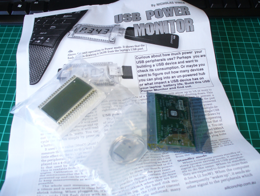
As usual for Altronics the kit is in a typical retail package:

…which includes the detailed instructions (based on the original Silicon Chip article), a handy reference guide and of course the parts:

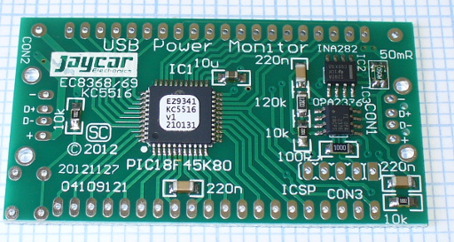
The PCB has a good silk screen and solder mask:


and all the required parts are included:

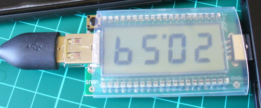
It was nice to see plenty of extra black and red wire for modifications or final installations, the battery snap, 2 x AA cell holder and a DC socket for use with the optional plug pack mentioned earlier. That hand-wound inductor was interesting, and I couldn’t help but measure it on the LC meter:

It was supposed to be a 47 uH inductor, so let’s hope that doesn’t cause too much trouble. Assembly was quite straight-forward – just start with the smallest components first and build up. If you’re not going to have the trickle-charge function, heed the notes in the manual and don’t install D2 or R4. The only fiddly bit was the “short as possible” (red) link across the board:

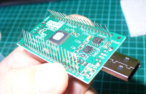
And after a few more minutes it was finished. The external connections will vary depending on your application – however for the review I’ve got the 9V snap on the input, which makes it easy to connect the 2 AA cell holder to power the converter. Nice to see the holes around the perimeter of the board, which make mounting it more permanently quite easy.
Operation
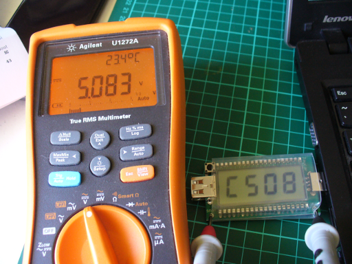
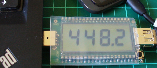
After a bench clean-up it was time to connect 2 AA rechargeable cells and see what we can get out of the converter. The cells measured 2.77V together before connection, and without a load on the converter the resulting output was 8.825 V:

We can live with that. Furthermore the quiescent current (a situation with the power connected and not having a load on the output) was 2.5 mA. Thus it would be a good idea to have a power switch in a real-world environment. Speaking of the real world (!) how much current can you get out of the converter? Generally PP3 battery applications are low current, as the battery itself isn’t good for that much – even an expensive “Energizer Ultimate Lithium” offers only 800 mAh (for $16). So using higher-capacity rechargeable AA cells and this kit will save money. A table is included with the instructions that shows the possible uses:

According to the table my 2.77V supply should be good for ~80 mA. With some resistors in parallel we made a dummy load of 69 mA and measured 0.37A current draw from the AA cells. Thus the key to this kit – you find a cheaper or more plentiful power supply at a lower voltage to save you the expense of providing the higher voltage.
For example, if you had a pair of Sanyo Eneloop rechargeable AA cells (total 2.4 V at 2 Ah) they would give you around 5.4 hours of life (ignoring the fall-off of voltage towards the end of their charge life – however the eneloops are pretty good in that regard). Whereas a disposable PP3 mentioned earlier would offer around 2.1 hours (at $16) or a rechargeable unit (which offers 8.4 V at 175 mAh) would only last around 25 minutes. Note that you can change two resistors in the circuit to alter the output voltage, and the values have been listed in the instructions for outputs up to 15 V.
Finally, let’s consider the output waveforms from the circuit. With the aforementioned load, here’s the output on the DSO:

… and for interest’s sake, the switching output from the TL499:


Conclusion
Apart from the described voltage-boosting functions this kit gives the interested builder experience with boost circuits and also the knowledge to create their own versions based on the original design, at a much lower cost than using other boost ICs . If you wanted a permanent certain voltage output, it would be better to breadboard the kit and experiment with the required resistors – then assemble the kit with the new values. And there is money and effort to be saved when subsituting with PP3 batteries. Finally, learning is a good thing!
So – a lot of fun and education for under $20. Purchase it from Altronics and their resellers, or read more about it in the September 2007 edition of Silicon Chip.
Full-sized images available on flickr. This kit was purchased without notifying the supplier.
And if you made it this far – check out my new book “Arduino Workshop” from No Starch Press.

In the meanwhile have fun and keep checking into tronixstuff.com. Why not follow things on twitter, Google+, subscribe for email updates or RSS using the links on the right-hand column? And join our friendly Google Group – dedicated to the projects and related items on this website. Sign up – it’s free, helpful to each other – and we can all learn something.
The post Kit review – Altronics/Silicon Chip DC to DC Converter appeared first on tronixstuff.