Posts | Comments

Planet Arduino

Archive for the ‘silicon chip’ Category

Introduction

Every month Australian electronics magazine Silicon Chip publishes a variety of projects, and in February 1994 they published the “90 Second Digital Message Recorder” project. That was a long time ago, however you can still find the kit today at Altronics (and at the time of writing, on sale for AU$26), and thus the subject of our review.

The kit offers a simple method of recording and playing back 90 seconds of audio, captured with an electret microphone. When mounted in a suitable enclosure it will make a neat way of leaving messages or instructions for others at home.

Assembly

The kit arrives in typical Altronics fashion:

Altronics K9570 90 second message recorder kit package

… and includes everything required including IC sockets for the ISD2590 and the audio amplifier:

Altronics K9570 90 second message recorder kit inclusions

Altronics K9570 90 second message recorder kit components

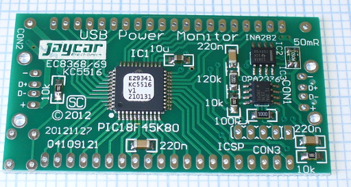
The PCB missed out on silk-screening – which is a pity:

Altronics K9570 90 second message recorder kit instructions PCB front

however it is from an original design from twenty years ago. The solder mask is neat and helps prevent against lazy soldering mistakes:

Altronics K9570 90 second message recorder kit PCB back

Finally the detailed instructions including component layout and the handy Altronics reference guide are also included. After checking and ordering the resistors, they were installed first along with the links:

Altronics K9570 90 second message recorder kit construction

 If you have your own kit, there is a small error in the instructions. The resistor between the 2k2 and the 10uF electrolytic at the top of the board is 10k0 not 2k2. Moving on, these followed by the capacitors and other low-profile components:

Altronics K9570 90 second message recorder kit construction 4

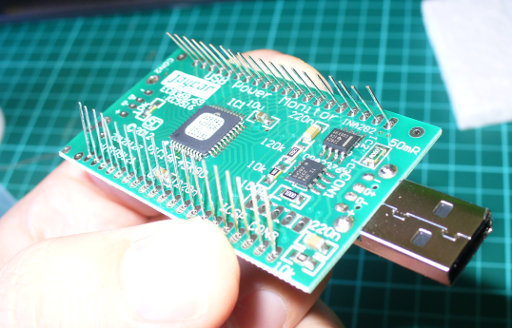
The rest of the components went in without any fuss, and frankly it’s a very easy kit to assemble:

Altronics K9570 90 second message recorder kit finished

 The required power supply is 6V, and a power switch and 4 x AA cell holder is included however were omitted for the review.

How it works

Instead of some fancy microcontrollers, the kit uses an ISD2590P single chip voice recording and playback IC:

Altronics K9570 90 second message recorder kit ISD2590

It’s a neat part that takes care of most of the required functions including microphone preamp, automatic gain control, and an EEPROM to store the analogue voltage levels that make up the voice sample. The ISD2590 samples audio at 5.3 kHz which isn’t CD quality, but enough for its intended purpose.

Apart from some passive components for power filtering, controls and a speaker amplifier there isn’t much else to say. Download the ISD2590 data sheet (pdf), which is incredibly detailed including some example circuits.

Operation

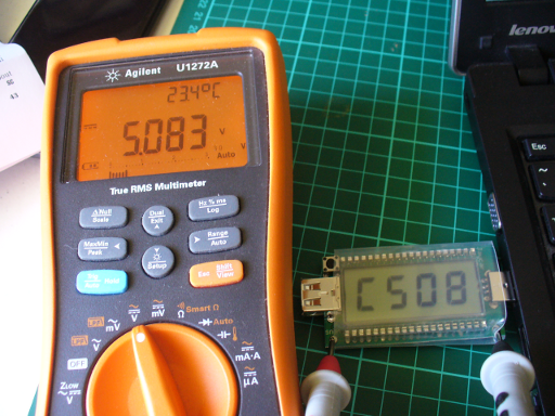
Once you apply power it’s a simple matter of setting the toggle switch on the PCB down for record, or up for playback. You can record in more than one session, and each session is recorded in order until the memory is full. Then the sounds can be played back without any fuss.

The kit is supplied with the generic 0.25W speaker which is perhaps a little weak for the amplifier circuit in the kit, however by turning down the volume a little the sound is adequate. In this video you can see (and hear) a quick recording and playback session.

Conclusion

This kit could be the base for convenient message system – and much more interesting than just scribbling notes for each other. Or you could built it into a toy and have it play various tunes or speech to amuse children. And for the price it’s great value to experiment with an ISD2590 – just use an IC socket. Or just have some fun  – we did.  Full-sized images are available on flickr

And if you enjoyed this article, or want to introduce someone else to the interesting world of Arduino – check out my book (now in a third printing!) “Arduino Workshop”.

visit tronixlabs.com

Have fun and keep checking into tronixstuff.com. Why not follow things on twitterGoogle+, subscribe  for email updates or RSS using the links on the right-hand column, or join our forum – dedicated to the projects and related items on this website. Sign up – it’s free, helpful to each other –  and we can all learn something.

Introduction

Every month Australian electronics magazine Silicon Chip publishes a few projects, and in this kit review we’ll look at an older but still current example from August 2004 – the 3-state Logic Probe Kit (Mk II). This is an inexpensive piece of test equipment that’s useful when checking digital logic states and as a kit, great for beginners. Avid readers of my kit reviews may remember the SMD version we examined in June… well it wasn’t that much of a success due to the size of the parts. However this through-hole version has been quite successful, so keep reading to find out more

Assembly

The kit is packaged in typical form, without any surprises:

bag

 In typical Altronics fashion, an updated assembly guide is provided along with a general reference to common electronics topics:

bagcontents

 All the required parts are included – except for a 14-pin IC socket and two CR2016 batteries.

parts

 The PCB makes soldering easy with the silk-screen and solder mask:

pcbtop

 However the resistor numbering is a bit out of whack, a few R-numbers are skipped. So before soldering, measure and line up all the resistors in numbered order – doing so will reduce the chance of fitting them in the wrong spot.

pcbbottom

When it comes time to solder the power switch on the end, it’s necessary to clip off two tabs – one at each end of the switch. However this isn’t a problem:

solderswitchon

Soldering in the rest of the components wasn’t any effort at all, they’ve been spaced around the PCB nicely:

gettingthere

 Once they’re in, it’s time to insert the pins that hold the probe (shown on the left below):

pinsforprobe

 A full-sized probe is included with the kit, which you cut down with a hacksaw to allow it to fit on the end of the PCB. Then solder a short wire from the tip’s collar and run it through the body as such:

pinsforprobe2

 At this point, it’s time to break out the butane torch:

blowtorch

… with which you melt down the heatshrink over the tip, then fit it to the PCB and solder the probe wire:

testing

At this point it’s wise to fit the batteries and test that the probe works, as the next stage is to heatshrink the entire circuit to the left of the LEDs:

finished

Use

Using the probe is incredibly simple – however note that it’s designed for working with 5V logic. If you need to use higher voltages the probe can be assembled with slightly different circuit to take care of that eventuality. Moving forward simply clip the lead to GND on the circuit under test, then probe where you want to measure. The LEDs will indicate either HIGH, LOW or the PULSE LED will light when a fault is apparent, or other need for further research into the circuit. Here’s a quick demonstration probing a signal from an Arduino board:

Conclusion

This through-hole version of the logic probe kit was much easier to construct than the SMD version, and worked first time. A logic probe itself is a very useful tool to have and I highly recommend this kit for the beginner who enjoys projects and is growing their stable of test equipment on a budget. You can find the kit at Altronics and their distributors.

Full-sized images available on flickr.  And if you made it this far – check out my new book “Arduino Workshop” from No Starch Press.

In the meanwhile have fun and keep checking into tronixstuff.com. Why not follow things on twitterGoogle+, subscribe  for email updates or RSS using the links on the right-hand column? And join our friendly Google Group – dedicated to the projects and related items on this website. Sign up – it’s free, helpful to each other –  and we can all learn something.

[Note - kit purchased without notifying the supplier]

The post Kit review – Altronics Logic Probe Mk II appeared first on tronixstuff.

Introduction

Every month Australian electronics magazine Silicon Chip publishes a variety of projects, and in March 2004  they published the “DC-DC converter” project. Altronics picked it up and now offers a kit, the subject of our review. The main purpose of this converter kit is to allow replacement of expensive PP3 9V batteries with 2 AA cells, to enable a cheaper and longer lifespan over use. With a slight modification it can also act as a trickle-charger for 2 rechargeable AA cells (that can then supply power to the converter) via a plugpack. And there’s some educational value if you’re so inclined, as you can learn about voltage converters as well.

Assembly

As usual for Altronics the kit is in a typical retail package:

packaged

…which includes the detailed instructions (based on the original Silicon Chip article), a handy reference guide and of course the parts:

contents

The PCB has a good silk screen and solder mask:

pcbtop

pcbbottom

and all the required parts are included:

components

It was nice to see plenty of extra black and red wire for modifications or final installations, the battery snap, 2 x AA cell holder and a DC socket for use with the optional plug pack mentioned earlier. That hand-wound inductor was interesting, and I couldn’t help but measure it on the LC meter:

lcmeter

It was supposed to be a 47 uH inductor, so let’s hope that doesn’t cause too much trouble. Assembly was quite straight-forward – just start with the smallest components first and build up. If you’re not going to have the trickle-charge function, heed the notes in the manual and don’t install D2 or R4. The only fiddly bit was the “short as possible” (red) link across the board:

longlink

And after a few more minutes it was finished. The external connections will vary depending on your application – however for the review I’ve got the 9V snap on the input, which makes it easy to connect the 2 AA cell holder to power the converter. Nice to see the holes around the perimeter of the board, which make mounting it more permanently quite easy.

Operation

After a bench clean-up it was time to connect 2 AA rechargeable cells and see what we can get out of the converter. The cells measured 2.77V together before connection, and without a load on the converter the resulting output was 8.825 V:

firsttest

We can live with that. Furthermore the quiescent current (a situation with the power connected and not having a load on the output) was 2.5 mA. Thus it would be a good idea to have a power switch in a real-world environment. Speaking of the real world (!) how much current can you get out of the converter? Generally PP3 battery applications are low current, as the battery itself isn’t good for that much – even an expensive “Energizer Ultimate Lithium” offers only 800 mAh (for $16). So using higher-capacity rechargeable AA cells and this kit will save money.  A table is included with the instructions that shows the possible uses:

tableofuse

According to the table my 2.77V supply should be good for ~80 mA. With some resistors in parallel we made a dummy load of 69 mA and measured 0.37A current draw from the AA cells. Thus the key to this kit – you find a cheaper or more plentiful power supply at a lower voltage to save you the expense of providing the higher voltage.

For example, if you had a pair of Sanyo Eneloop rechargeable AA cells (total 2.4 V at 2 Ah) they would give you around 5.4 hours of life (ignoring the fall-off of voltage towards the end of their charge life – however the eneloops are pretty good in that regard). Whereas a disposable PP3 mentioned earlier would offer around 2.1 hours (at $16) or a rechargeable unit (which offers 8.4 V at 175 mAh) would only last around 25 minutes. Note that you can change two resistors in the circuit to alter the output voltage, and the values have been listed in the instructions for outputs up to 15 V.

Finally, let’s consider the output waveforms from the circuit. With the aforementioned load, here’s the output on the DSO (click image to enlarge):

output

… and for interest’s sake, the switching output from the TL499 (click images to enlarge):

switchoutput

switchoutputdata

Conclusion

Apart from the described voltage-boosting functions this kit gives the interested builder experience with boost circuits and also the knowledge to create their own versions based on the original design, at a much lower cost than using other boost ICs . If you wanted a permanent certain voltage output, it would be better to breadboard the kit and experiment with the required resistors – then assemble the kit with the new values. And there is money and effort to be saved when subsituting with PP3 batteries. Finally, learning is a good thing!

So – a lot of fun and education for under $20. Purchase it from Altronics and their resellers, or read more about it in the September 2007 edition of Silicon Chip.

Full-sized images available on flickr. This kit was purchased without notifying the supplier.

And if you made it this far – check out my new book “Arduino Workshop” from No Starch Press.

In the meanwhile have fun and keep checking into tronixstuff.com. Why not follow things on twitterGoogle+, subscribe  for email updates or RSS using the links on the right-hand column? And join our friendly Google Group – dedicated to the projects and related items on this website. Sign up – it’s free, helpful to each other –  and we can all learn something.


Introduction

Every month Australian electronics magazine Silicon Chip publishes a variety of projects, and in March 2004  they published the “DC-DC converter” project. Altronics picked it up and now offers a kit, the subject of our review. The main purpose of this converter kit is to allow replacement of expensive PP3 9V batteries with 2 AA cells, to enable a cheaper and longer lifespan over use. With a slight modification it can also act as a trickle-charger for 2 rechargeable AA cells (that can then supply power to the converter) via a plugpack. And there’s some educational value if you’re so inclined, as you can learn about voltage converters as well.

Assembly

As usual for Altronics the kit is in a typical retail package:

packaged

…which includes the detailed instructions (based on the original Silicon Chip article), a handy reference guide and of course the parts:

contents

The PCB has a good silk screen and solder mask:

pcbtop

pcbbottom

and all the required parts are included:

components

It was nice to see plenty of extra black and red wire for modifications or final installations, the battery snap, 2 x AA cell holder and a DC socket for use with the optional plug pack mentioned earlier. That hand-wound inductor was interesting, and I couldn’t help but measure it on the LC meter:

lcmeter

It was supposed to be a 47 uH inductor, so let’s hope that doesn’t cause too much trouble. Assembly was quite straight-forward – just start with the smallest components first and build up. If you’re not going to have the trickle-charge function, heed the notes in the manual and don’t install D2 or R4. The only fiddly bit was the “short as possible” (red) link across the board:

longlink

And after a few more minutes it was finished. The external connections will vary depending on your application – however for the review I’ve got the 9V snap on the input, which makes it easy to connect the 2 AA cell holder to power the converter. Nice to see the holes around the perimeter of the board, which make mounting it more permanently quite easy.

Operation

After a bench clean-up it was time to connect 2 AA rechargeable cells and see what we can get out of the converter. The cells measured 2.77V together before connection, and without a load on the converter the resulting output was 8.825 V:

firsttest

We can live with that. Furthermore the quiescent current (a situation with the power connected and not having a load on the output) was 2.5 mA. Thus it would be a good idea to have a power switch in a real-world environment. Speaking of the real world (!) how much current can you get out of the converter? Generally PP3 battery applications are low current, as the battery itself isn’t good for that much – even an expensive “Energizer Ultimate Lithium” offers only 800 mAh (for $16). So using higher-capacity rechargeable AA cells and this kit will save money.  A table is included with the instructions that shows the possible uses:

tableofuse

According to the table my 2.77V supply should be good for ~80 mA. With some resistors in parallel we made a dummy load of 69 mA and measured 0.37A current draw from the AA cells. Thus the key to this kit – you find a cheaper or more plentiful power supply at a lower voltage to save you the expense of providing the higher voltage.

For example, if you had a pair of Sanyo Eneloop rechargeable AA cells (total 2.4 V at 2 Ah) they would give you around 5.4 hours of life (ignoring the fall-off of voltage towards the end of their charge life – however the eneloops are pretty good in that regard). Whereas a disposable PP3 mentioned earlier would offer around 2.1 hours (at $16) or a rechargeable unit (which offers 8.4 V at 175 mAh) would only last around 25 minutes. Note that you can change two resistors in the circuit to alter the output voltage, and the values have been listed in the instructions for outputs up to 15 V.

Finally, let’s consider the output waveforms from the circuit. With the aforementioned load, here’s the output on the DSO:

output

… and for interest’s sake, the switching output from the TL499:

switchoutput

switchoutputdata

Conclusion

Apart from the described voltage-boosting functions this kit gives the interested builder experience with boost circuits and also the knowledge to create their own versions based on the original design, at a much lower cost than using other boost ICs . If you wanted a permanent certain voltage output, it would be better to breadboard the kit and experiment with the required resistors – then assemble the kit with the new values. And there is money and effort to be saved when subsituting with PP3 batteries. Finally, learning is a good thing!

So – a lot of fun and education for under $20. Purchase it from Altronics and their resellers, or read more about it in the September 2007 edition of Silicon Chip.

Full-sized images available on flickr. This kit was purchased without notifying the supplier.

And if you made it this far – check out my new book “Arduino Workshop” from No Starch Press.

LEDborder

In the meanwhile have fun and keep checking into tronixstuff.com. Why not follow things on twitterGoogle+, subscribe  for email updates or RSS using the links on the right-hand column? And join our friendly Google Group – dedicated to the projects and related items on this website. Sign up – it’s free, helpful to each other –  and we can all learn something.

The post Kit review – Altronics/Silicon Chip DC to DC Converter appeared first on tronixstuff.

Feb
12

Introduction

Every month Australian electronics magazine Silicon Chip publishes a variety of projects, and in January 2013 they published the “Garbage Recycling Reminder” by John Clarke. Jaycar picked it up and now offers a kit, the subject of our review. This kit solves the old but recurring (for some) problem – which bin to put out, and when!

The kit offers a simple way of keeping track of the bin schedule, and is suitable for up to four bins. With a simple user-interface consisting of a button and LED for each bin – once setup the reminder can easily be used by anyone. It allows for weekly, fortnightly and alternate fortnights – which is perfect for almost every council’s schedule.

Assembly

The kit arrives in typical Jaycar fashion:

and includes everything you need, including an enclosure, front panel sticker and battery:

 The PCB is well done, and routed nicely to fit inside the enclosure:

Now to get started. The instructions included are a reprint of the magazine article, and as Jaycar have modified the kit a little, their notes and photos are also included. However there isn’t anything to worry about.

Assembly is straight-forward, the only annoying thing was the assumption that the constructor will use off-cuts for jumper links. Instead – use your own header pins:

Furthermore, when soldering in the resistors and 1N914 diodes next to the LEDs – leave them floating so you can move them a bit to make way for the LEDs:

This is also a good time to check the buttons line up with the holes drilled into the front panel (a template is included with the instructions):

At this point you can fit the LEDs to the PCB, and carefully match it up with the drilled lid. You are supplied with a red, green, yellow and blue LED – which generally match the bin lid colours from various councils. Screw the PCB into the lid then solder the LEDs in – after double-checking they protrude out of lid. Then insert the battery and make a final test:

If you made it that far, you can apply the sticker included to illustrate the front panel. To save time we cut the sticker up for a minimalist look. However you now need to set-up the jumpers before closing the box up. There is a set of three pins for each bin, and a jumper can bridge the first two or last two pins, or none. If you don’t bridge them – that bin is weekly. If you bridge the first two – that bin is fortnightly from the setup day. If you bridge the last two – that bin is fortnightly from the next week, for example:

So you can easily set it up for a weekly bin and an alternating-fortnight pair of bins. Once you’ve setup the jumpers, screw up the box and you’re done.

Operation

Once you’ve set the jumpers up as described earlier, you just need to execute the programming function at the time you want the reminders to start every week. For example, if your weekly collection is 4 AM on a Thursday – do the programming around 5pm Wednesday night – that will then be the time the LEDs start blinking. When you put out the appropriate bin, press the button below the matching bin LED to stop the blinking. You can control the number of bins – so if you only have two bins, only two LEDs will activate. The blinking period is eighteen hours, and you can adjust the start time via the buttons.

How it works

The circuit is based around a Microchip PIC16LF88 and has an incredibly low current draw, around 15 uA when the LEDs aren’t blinking. This allows the circuit to run for over two years on the included 3v coin cell battery. The internal clock is kept accurate to around 10 minutes per year using an external 32.768 kHz crystal. After a period of use the battery voltage may drop to a level insufficient to adequately power the LEDs, so each one has a voltage doubler by way of a diode and capacitor – very clever. This ensures LED brightness even with a low battery. For complete details purchase the kit or a copy of the January 2013 edition of Silicon Chip.

Now it sits next to the kettle, waiting for bin night…

Conclusion

Personally I needed this kit, so I’m a little biased towards it. However – it’s simple and it works. Kudos to John Clarke for his project. You can purchase it from Jaycar and their resellers, or read more about it in the January 2013 edition of Silicon Chip. Full-sized images available on flickr. This kit was purchased without notifying the supplier.

In the meanwhile have fun and keep checking into tronixstuff.com. Why not follow things on twitterGoogle+, subscribe  for email updates or RSS using the links on the right-hand column? And join our friendly Google Group – dedicated to the projects and related items on this website. Sign up – it’s free, helpful to each other –  and we can all learn something.

The post Kit Review – SC/Jaycar Garbage and Recycling Reminder appeared first on tronixstuff.

Introduction

Every month Australian electronics magazine Silicon Chip publishes a variety of projects, and in December 2012 they published the USB Power Monitor by Nicholas Vinen. Jaycar picked it up and now offers a kit, the subject of our review. This small device plugs inline between a USB port and another device, and can display the current drawn, power and voltage at the USB port with a large LCD module. This is useful when you’re experimenting with USB-powered devices such as Arduino projects or curious how external USB devices can affect your notebook computer’s battery drain.

Assembly

The kit arrives in typical Jaycar fashion:

… everything necessary is included with the kit:

The instructions arrive as an updated reprint of the original magazine article, plus the usual notes from Jaycar about warranty and their component ID sheet which is useful for beginners. The PCB is quite small, and designed to be around the same size as the LCD module:

As you can see below, most of the work is already done due to the almost exclusive use of SMD components:

That’s a good thing if you’re in a hurry (or not the best with surface-mount work). Therefore the small amount of work requires is simply to solder in the USB sockets, the button and the LCD:

It took less than ten minutes to solder together. However – take careful, careful note of the LCD. There isn’t a pin 1 indicator on the module – so instead hold the LCD up to the light and determine which side of the screen has the decimal points – and line it up matching the silk-screening on the PCB. Once finished you can add the clear heatshrink to protect the meter, but remember to cut a small window at the back if you want access to the ICSP pins for the PIC microcontroller:

How it works

The USB current is passed through a 50 mΩ shunt resistor, with the voltage drop being measured by an INA282 current shunt monitor IC. The signal from there is amplified by an op amp and then fed to the ADC of a PIC18F45K80 microcontroller, which does the calculations and drives the LCD. For complete details purchase the kit or a copy of the December 2012 edition of Silicon Chip.

Operation

First you need to calibrate the unit – when first used the meter defaults to calibration mode. You simply insert it into a USB port. then measure the USB DC voltage brought out to two pads on the meter. By pressing the button you can match the measured voltage against the display as shown below – then you’re done.

Then you simply plug it in between your USB device and the socket. Press the button to change the measurement. The meter can measure the following ranges:

For an operational example. consider the next three images are from charging my phone – with the power, current and voltage being shown:

“P” for power…

current in mA

“b” for bus voltage

If you want to use the USB ports on the right-hand side of your computer, just press the button while inserting the meter – and it flips around:

Finally – here’s a quick video of the meter at work, whilst copying a file to an external USB hard drive:

Conclusion

I really like this – it’s simple and it works. Kudos to Nicholas for his project. You can purchase it from Jaycar and their resellers, or read more about it in the December 2012 edition of Silicon Chip. Full-sized images available on flickr. This kit was purchased without notifying the supplier.

In the meanwhile have fun and keep checking into tronixstuff.com. Why not follow things on twitterGoogle+, subscribe  for email updates or RSS using the links on the right-hand column? And join our friendly Google Group – dedicated to the projects and related items on this website. Sign up – it’s free, helpful to each other –  and we can all learn something.

The post Kit Review – SC/Jaycar USB Power Monitor appeared first on tronixstuff.


  • Newsletter

    Sign up for the PlanetArduino Newsletter, which delivers the most popular articles via e-mail to your inbox every week. Just fill in the information below and submit.

  • Like Us on Facebook