Posts | Comments

Planet Arduino

Archive for the ‘ldr’ Category

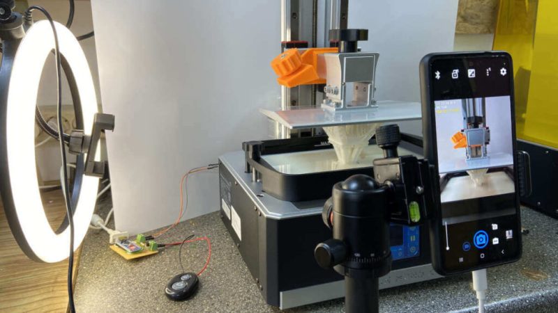
With how cheap they’re getting, everyone seems to be jumping on the resin printer bandwagon. They may not be able to fully replace your trusty old FDM printer, but for certain jobs, they just can’t be beaten. Sadly though, creating those smooth time-lapse videos of your prints isn’t quite as easy to do as it is on their filament-based counterparts.

Not as easy, perhaps, but not impossible. [Fraens] found a way to make time-lapses on any resin printer, and in a wonderfully hacky way. First, you need to find a smartphone, which shouldn’t be too hard, given how often we all tend to upgrade. [Fraens] recommends replacing the standard camera app on the phone with Open Camera, to prevent it from closing during the long intervals with nothing happening. The camera is triggered by any readily available Bluetooth dongle, which is connected via a simple transistor circuit to an Arduino output. To trigger the shutter, a light-dependent resistor (LDR) is connected to one of the microcontroller’s inputs. The LDR is placed inside the bed of the resin printer — an Anycubic Photon in this case — where light from the UV panel used to cross-link the resin can fall on it. A simple bit of Arduino code triggers the Bluetooth dongle at the right moment, capturing a series of stills which are later stitched together using DaVinci Resolve.

The short video below shows the results, which look pretty good to us. There are other ways to do this, of course, but we find the simplicity of this method pleasing.

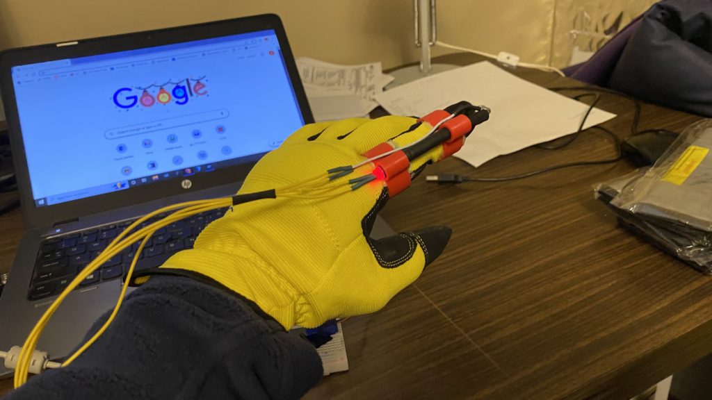
In order to build wearables that react to movement, most people tend to reach for accelerometers, gyroscopes, and flex sensors. But due to their higher cost, one of teacher Gord Payne’s students wanted to create a low-cost alternative that could be easily sourced and integrated into projects.

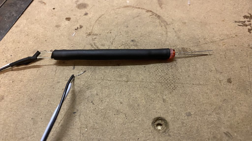
A typical glove with finger movement tracking normally incorporates flexible strips, which vary in resistance based on the extent of their deviation from the starting angle. By reading this value with an Arduino board’s analog-to-digital converter (ADC) and mapping the resistance with a formula, the total angle can be found with decent accuracy. The student’s idea, however, substituted this special material for a flexible tube that has an LED on one end and a light-dependent resistor (LDR) on the other. When kept at the starting position, all of the light from the LED is able to hit the LDR, and any bends introduced from bending the tube cause less light to reach the other side.

After performing a few test runs to determine the exact mapping of resistance values coming from the LDR compared to the angle of the finger, the student’s code could accurately calculate the angle based on a simple formula. To demonstrate this project, a servo was connected to the microcontroller and made to mimic how the finger is moved.

More information can be found here on Payne’s Hackaday.io write-up

The post Substituting a flex sensor for an inexpensive light-dependent resistor appeared first on Arduino Blog.

While researching how to detect a laser beam configured as a tripwire I came across a number of ‘recommended’ ways to do this. I decided to test the two cheapest viable options – an LDR and LED – to see which would best suit my needs.

The sensor requirements for this application are relatively simple – detect a low power red laser beam interrupted by something passing through the it. The sensor needs to provide a reliable on/off signal within a few milliseconds of the event. It should also be inexpensive and implementable with a minimum of supporting passive components (ie, no op-amps, transistors, etc).

The two candidates that could suit this application are a

  • Light Dependent Resistor (LDR).
  • Light Emitting Diode (LED) used as a photodiode.

Light Dependent Resistor

A LDR (also known as photoresistor or photocell) is a passive component that decreases resistance when exposed to increased light intensity. The resistance range can span orders of magnitude when exposed to light – from as several megaohms to as low as a few hundred ohms.

Inexpensive cadmium sulfide (CdS) cells are readily available and can be found in many consumer items. Importantly for this application, LDRs are also commonly used in laser-based security systems to detect the laser beam is interrupted.

LDRs are usually configured as in voltage divider (see the circuit here) that provides a voltage proportional to the light intensity to a microporcessor’s analog input.

Light Emitting Diode

A Light Emitting Diode (LED) is a semiconductor light source that emits light when current flows through it. The color of the light is determined by the energy required for electrons to cross the band gap of the semiconductor and commonly enhanced by the color of the encapsulating plastic lens.

In addition to emitting light, a LED can be used as a photodiode light sensor/detector. When used this way, a LED is sensitive to wavelengths equal to or shorter than the predominant wavelength it emits. The current produce is very small (microamps).

The small current produced can be measured using high impedance inputs common in modern microprocessors. The LED is wired in a circuit ‘as normal’ with the microprocessor pin configured as an analog input measuring the voltage generated by the light detection, which should be about the same as the LED forward voltage.

Testing

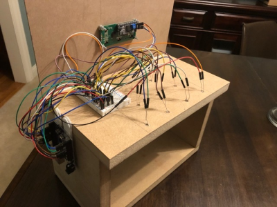
The test hardware setup shown below is built up from my standardized prototyping mini-circuits (see this previous article) and the software used is found at the end of this article.

A small 5mW red laser is directly connected to an output pin and can be turned on/off using a tact switch connected to input pin.

The LDR/LED sensors are in turn connected to a third input pin and sampled by the software. The Arduino board’s bult-in LED is used to indicate the binary sensor output and the corresponding analog values are written to the serial monitor.

The LED had a few shortcomings in this application. The analog range was relatively small (260 to 140) making it tricky to find the on/off threshold. The sensor values read also jumped around quite a bit, so each reading was actually the average of multiple reads with senor recovery delays between each reading.

The LDR performed the best for this application. The sensor was 100% reliable, with the analog values reported between 1000 (exposed to the laser) and 100 (dark). This large range makes it easy to convert to an on/off signal. The sensor could also be read in one operation and requires minimal software additional hardware to use.


Test Code

// Test Laser Tripwire
//
// Test laser sensor types
// Switch off the built-in LED when the laser is blocked
//
// MD_UISwitch from https://github.com/MajicDesigns/MD_UISwitch or Arduino Library Manager


#include <MD_UISwitch.h>

#define TEST_LDR 1
#define TEST_LED 0

const uint8_t PIN_LASER = 12;
const uint8_t PIN_DETECT = A0;
const uint8_t PIN_SWITCH = 3;

MD_UISwitch_Digital sw(PIN_SWITCH); // laser toggle switch

void setup(void) 
{
  Serial.begin(57600);
  Serial.print(F("\n[Laser Test]"));
  pinMode(PIN_LASER, OUTPUT);
  pinMode(PIN_DETECT, INPUT);
  pinMode(LED_BUILTIN, OUTPUT);
  sw.begin();
}

#if TEST_LDR
const uint16_t threshold = 200;

inline uint16_t readSensor(void)
{
  return(analogRead(PIN_DETECT));
}
#endif

#if TEST_LED
// LED is in circuit with anode in the PIN_DETECT and gnd to ground
const uint16_t threshold = 160;
const uint8_t samples = 20;
const uint16_t recovery = 2;

uint16_t readSensor(void)
{
  uint32_t sens = 0; 

  for (uint8_t i = 0; i < samples; i++) // remember the lowest value out of many readings
  {
    sens += analogRead(PIN_DETECT);
    delay(recovery);                 // the sensor needs a delay here to catch its breath
  }
  sens /= samples;

  return(sens);
}
#endif

void loop(void)
{
  // toggle laser on/off with momentary switch
  if (sw.read() == MD_UISwitch::KEY_PRESS)
    digitalWrite(PIN_LASER, digitalRead(PIN_LASER) == LOW ? HIGH : LOW);

  // display the value of the input detected
  uint16_t v = readSensor();
  
  digitalWrite(LED_BUILTIN, v < threshold ? HIGH : LOW);

  Serial.print(F("\n"));
  Serial.print(v < threshold);
  Serial.print(F("  "));
  Serial.print(v);
}
Bowling has been around since ancient Egypt and continues to entertain people of all ages, especially once they roll out the fog machine and hit the blacklights. But why pay all that money to don used shoes and drink watered-down beer? Just build a tabletop bowling alley in your spare time and you can bowl barefoot if you want.

Those glowing pins aren’t just for looks — the LEDs underneath them are part of the scoring system. Whenever a pin is knocked out of its countersunk hole, the LED underneath is exposed and shines its light on a corresponding light-dependent resistor positioned overhead. An Arduino Uno keeps track of of the frame, ball number, and score, and displays it on an LCD.

The lane is nearly six feet long, so this is more like medium-format bowling or maybe even skee-bowling. There are probably a number of things one could use for balls, but [lainealison] is using large ball bearings. Roll past the break to see it in action, but don’t go over the line!

Can’t keep your balls out of the gutter? Build a magic ball and make all wishful leaning more meaningful as you steer it down the lane with your body.

Mankind will always wonder whether we’re alone in the universe. What is out there? Sure, these past weeks we’ve been increasingly wondering the same about our own, direct proximity, but that’s a different story. Up until two years ago, we had the Kepler space telescope aiding us in our quest for answers by exploring exoplanets within our galaxy. [poblocki1982], who’s been fascinated by space since childhood times, and has recently discovered 3D printing as his new thing, figured there is nothing better than finding a way to combine your hobbies, and built a simplified model version simulating the telescope’s main concept.

The general idea is to detect the slight variation of a star’s brightness when one of its planets passes by it, and use that variation to analyze each planet’s characteristics. He achieves this with an LDR connected to an Arduino, allowing both live reading and logging the data on an SD card. Unfortunately, rocket science isn’t on his list of hobbies yet, so [poblocki1982] has to bring outer space to his home. Using a DC motor to rotate two “planets” of different size, rotation speed, and distance around their “star”, he has the perfect model planetary system that can easily double as a decorative lamp.

Obviously, this isn’t meant to detect actual planets as the real Kepler space telescope did, but to demonstrate the general concept of it, and as such makes this a nice little science experiment. For a more pragmatic use of our own Solar System, [poblocki1982] has recently built this self-calibrating sundial. And if you like rotating models of planets, check out some previous projects on that.

Have you shopped for an appliance lately? They’re all LEDs, LEDs everywhere. You might say that manufacturers are out of touch with the utility of tactile controls. [Wingletang]’s fancy new washing machine is cut from this modern cloth. While it does have a nice big knob for selecting cycles, the only indication of your selection is an LED. This isn’t an issue for [Wingletang], but it’s a showstopper for his visually impaired wife.

They tried to make tactile signposts for her most-used cycles with those adhesive rubber feet you use to keep cabinet doors quiet. But between the machine’s 14(!) different wash cycles and the endlessly-rotating selector knob, the tactile map idea was a wash. It was time to make the machine talk.

For his very first microcontroller project, [Wingletang] designed a completely non-invasive and totally awesome solution to this problem. He’s using LDRs arranged in a ring to detect which LED is lit. Recycled mouse pad foam and black styrene keep ambient light from creating false positives, and double as enclosure for the sensor and support boards. As [Mrs. Wingletang] cycles through with the knob, an Arduino clone mounted in a nearby project box determines which program is selected, and a Velleman KA02 audio shield plays a recorded clip of [Wingletang] announcing the cycle number and description.

The system, dubbed SOAP (Speech Output Announcing Programmes), has been a great help to [Mrs. Wingletang] for about the last year. Watch her take it for a spin after the break, and stick around for SOAP’s origin story and walk-through videos.

It’s baffling that so few washers and dryers let you know when they’re finished. Don’t waste your time checking over and over again—Laundry Spy waits for the vibrations to end and sends you a text.


The view from America has long seen French women as synonymous with thin and/or beautiful. France is well-known for culinary skill and delights, and yet many of its female inhabitants seem to view eating heartily as passé. At a recent workshop devoted to creating DIY amusements, [Niklas Roy] and [Kati Hyyppä] built an electro-mechanical sushi-eating game starring Barbie, American icon of the feminine ideal. The goal of the game is to feed her well and inspire a happy relationship with food.

Built in just three days, J’ai faim! (translation: I’m hungry!) lets the player satiate Barbie one randomly lit piece of sushi at a time. Each piece has a companion LED mounted beneath the surface that’s connected in series to the one on the game board. Qualifying sushi are determined by a photocell strapped to the underside of Barbie’s tongue, which detects light from the hidden LED. Players must race against the clock to eat each piece, taking Barbie up the satisfaction meter from ‘starving’ to ‘well-fed’. Gobble an unlit piece, and the score goes down.

The game is controlled with a lovely pink lollipop of a joystick, which was the main inspiration for the game. Players move her head with left and right, and pull down to engage the solenoid that pushes her comically long tongue out of her button-nosed face. Barbie’s brain is an Arduino Uno, which also controls the stepper motor that moves her head.

[Niklas] and [Kati] wound up using cardboard end stops inside the box instead of trying to count the rapidly changing steps as she swivels around. The first motor they used was too weak to move her head. The second one worked, but the game’s popularity combined with the end stops did a number on the gears after a day or so. Click past the break to sink your teeth into the demo video.

Barbie can do more than teach young girls healthy eating habits. She can also teach them about cryptography.

In our eyes, there isn’t a much higher calling for Arduinos than using them to make musical instruments. [victorh88] has elevated them to rock star status with his homemade electronic drum kit.

The kit uses an Arduino Mega because of the number of inputs [victorh88] included. It’s not quite Neil Peart-level, but it does have a kick drum, a pair of rack toms, a floor tom, a snare, a crash, a ride, and a hi-hat. With the exception of the hi-hat, all the pieces in the kit use a piezo element to detect the hit and play the appropriate sample based on [Evan Kale]’s code, which was built to turn a Rock Band controller into a MIDI drum kit. The hi-hat uses an LDR embedded in a flip-flop to properly mimic the range of an actual acoustic hi-hat. This is a good idea that we have seen before.

[victorh88] made all the drums and pads out of MDF with four layers of pet screen sandwiched in between. In theory, this kit should be able to take anything he can throw at it, including YYZ. The crash and ride cymbals are MDF with a layer of EVA foam on top. This serves two purposes: it absorbs the shock from the sticks and mutes the sound of wood against wood. After that, it was just a matter of attaching everything to a standard e-drum frame using the existing interfaces. Watch [victorh88] beat a tattoo after the break.

If you hate Arduinos but are still reading for some reason, here’s a kit made with a Pi.


Filed under: Arduino Hacks, musical hacks
Mar
05

[Carl] recently upgraded his home with a solar panel system. This system compliments the electricity he gets from the grid by filling up a battery bank using free (as in beer) energy from the sun. The system came with a basic meter which really only shows the total amount of electricity the panels produce. [Carl] wanted to get more data out of his system. He managed to build his own monitor using an Arduino.

The trick of this build has to do with how the system works. The panel includes an LED light that blinks 1000 times for each kWh of electricity. [Carl] realized that if he could monitor the rate at which the LED is flashing, he could determine approximately how much energy is being generated at any given moment. We’ve seen similar projects in the past.

Like most people new to a technology, [Carl] built his project up by cobbling together other examples he found online. He started off by using a sketch that was originally designed to calculate the speed of a vehicle by measuring the time it took for the vehicle to pass between two points. [Carl] took this code and modified it to use a single photo resistor to detect the LED. He also built a sort of VU meter using several LEDs. The meter would increase and decrease proportionally to the reading on the electrical meter.

[Carl] continued improving on his system over time. He added an LCD panel so he could not only see the exact current measurement, but also the top measurement from the day. He put all of the electronics in a plastic tub and used a ribbon cable to move the LCD panel to a more convenient location. He also had his friend [Andy] clean up the Arduino code to make it easier for others to use as desired.


Filed under: Arduino Hacks
Sep
06

Very accurate master clock synchronized to the DCF77 time signal

arduino, bluetooth, clock, dcf77, ldr Comments Off on Very accurate master clock synchronized to the DCF77 time signal 

master_clock_16a

by embedded-lab.com:

Brett’s new masterclock is Arduino-controlled and keeps very accurate time by periodically synchronizing with the DCF77 “Atomic” Clock in Mainflingen near Frankfurt, Germany. The DCF77  library for Arduino is used to decode the time signal broadcasted from the atomic clock. The time is displayed as hours, minutes, and seconds on six 1″ seven segment LEDs. A 4×20 I2C LCD display is also used in the project to display additional info such as display brightness, sync information, signal quality, auto tune’d frequency, auto tuned quartz accuracy, etc. Both the displays are auto-dimmed based on the surrounding light intensity using an LDR sensor and pulse width modulation technique. His clock also includes a bluetooth link for updating the Arduino firmware from a PC without an USB cable.

Very accurate master clock synchronized to the DCF77 time signal - [Link]


  • Newsletter

    Sign up for the PlanetArduino Newsletter, which delivers the most popular articles via e-mail to your inbox every week. Just fill in the information below and submit.

  • Like Us on Facebook