Posts | Comments

Planet Arduino

Archive for the ‘pcb’ Category

What is part way between a printed circuit board and a rats-nest of point-to-point wiring? We’re not sure, but this is it. [Johan von Konow] has come up with an inspired solution, 3D printing an Arduboy case with channels ready-made for all the wires. The effect with his 3DPCBoy is of a PCB without the PCB, and allows the console to be made very quickly and cheaply.

The Arduboy — which we originally looked at back in 2014 — is a handheld gaming console in a somewhat Gameboy-like form factor. Normally a credit-card sized PCB hosts all the components, including a microcontroller, display, and buttons. Each has a predictable footprint and placement so they can simply be wired together with hookup wire, if you don’t mind a messy result.

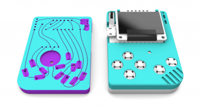
Here the print itself has all the holes ready-created for the components, and the path of the wires has a resemblance to the sweeping traces of older hand-laid PCBs. The result is very effective way to take common components — and Arduino pro micro board for the uC, an OLED breakout board, and some buttons — and combine them into a robust package. This technique of using 3D prints as a combination of enclosure and substrate for components and wiring has an application far beyond handheld gaming. We look forward to seeing more like it.

[Via the Arduboy community forum, thanks [Kevin Bates] for the tip.]

Engineers create something out of nothing, and no where is this more apparent than in the creation of customized computer hardware. To make a simple MIDI controller, you need knowledge of firmware design and computer architecture, you need knowledge of mechanical design, and you need to know electronic design. And then you need the actual working knowledge and experience to wield a tool, be it a hammer, laser cutter, or an IDE. [Mega Das] brought together all of these skill to build a MIDI controller. Sure, it’s for bleeps and bloops coming out of a speaker, but take a step back and realize just how awesome it is that any one person could imagine, then implement such a device.

The electronics for this build include a printed circuit board that serves to break out the connections on an Arduino nano to a dozen arcade push buttons, four slide pots, two rotary pots, and a handful of screw terminals to connect everything together. Mechanically, this is a laser-cut box engraved with some fancy graphics and sized perfectly to put everything inside.

Yes, we’ve seen a lot of MIDI controllers built around the Arduino over the years, but this one is in a class by itself. This is taking off-the-shelf parts and customizing them to exactly what you want, and a prodigious example of what is possible with DIY hardware creation. You can check out the build video below.

We’ve all got a box full of old PCBs, just waiting to be stripped of anything useful. [Dennis1a4] decided to do something with his, turning it into an attractive mosaic that he hung on the wall of his new workshop. But this isn’t just a pile of old PCBs: [Dennis1a4] decided to use the LEDs that were on many of the old boards, creating a blinky junk build. That’s kind of neat in itself, but he then decided to go further, building in an IR receiver so he could control the blinkiness, and a PIR sensor that detected when someone was near the mosaic.

This whole setup is controlled by an ATMega328p  that is driving a couple of PCF8575 port expanders that drive the LEDs. These blink in Morse code patterns. [Dennis1a4] also used an array of DIP switches on one of the boards to randomize the patterns, and wired in a pizeo buzzer on another board to make appropriate bleepy noises.

We’re all familiar with the wide variety of Arduino development boards available these days, and we see project after project wired up on a Nano or an Uno. Not that there’s anything wrong with that, of course, but there comes a point where some hobbyists want to move beyond plugging wires into header sockets and build the microcontroller right into their project. That’s when one generally learns that development boards do a lot more than break the microcontroller lines out to headers, and that rolling your own design means including all that supporting circuitry.

To make that transition easier, [Sean Hodgins] has come up with a simple Arduino-compatible module that can be soldered right to a PCB. Dubbed the “HCC Mod” for the plated half-circle castellations that allows for easy soldering, the module is based on the Atmel SAMD21 microcontroller. With 16 GPIO lines, six ADCs, an onboard 3.3 V regulator, and a reset button, the module has everything needed to get started — just design a PCB with the right pad layout, solder it on, and surround it with your circuitry. Programming is done in the familiar Arduino IDE so you can get up and running quickly. [Sean] has a Kickstarter going for the modules, but he’s also releasing it as open source so you’re free to solder up your own like he does in the video below.

It’s certainly not the first dev module that can be directly soldered to a PCB, but we like the design and can see how it would simplify designs. [Sean] as shown us a lot of builds before, like this army of neural net robots, so he’ll no doubt put these modules to good use.

[Allan Schwartz] decided to document his experience using Fritzing to design, fabricate, and test a custom Arduino shield PCB, and his step-by-step documentation makes the workflow very clear. Anyone who is curious or has been looking for an opportunity to get started will find [Allan]’s process useful to follow. The PCB in question has two shift registers, eight LEDs, eight buttons, and fits onto an Arduino; it’s just complex enough to demonstrate useful design features and methods while remaining accessible.

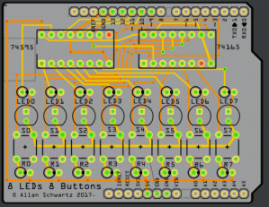
[Allan] starts with a basic breadboard design, draws a schematic, prototypes the circuit, then designs the PCB and orders it online, followed by assembly and testing. [Allan] had previously taught himself to use Eagle and etched his own PCBs via the toner transfer method, but decided to use Fritzing instead this time around and found it helpful and easy to use.

About a year ago we saw Fritzing put through its paces for PCB design, and at the time found that it didn’t impress much from an engineering perspective. Regardless, as a hobbyist [Allan] found real value in using Fritzing for his project from beginning to end; he documented both the process and his observations in order to help others, and that’s wonderful.


Filed under: Arduino Hacks, how-to

[Corey Harding] designed his business card as a USB-connectable demonstration of his skill. If potential manager inserts the card in a USB drive, open a text editor, then touches the copper pad on the PCB, [Corey]’s contact info pops up in the text box.

In addition to working as a business card, the PCB also works as a Tiny 85 development board, with a prototyping area for adding sensors and other components, and with additional capabilities broken out: you can add an LED, and there’s also room for a 1K resistor, a reset button, or break out the USB’s 5V for other uses. There’s an AVR ISP breakout for reflashing the chip.

Coolly, [Corey] intended for the card to be an Open Source resource for other people to make their own cards, and he’s providing the Fritzing files for the PCB. Fritzing is a great program for beginning and experienced hardware hackers to lay out quick and dirty circuits, make wiring diagrams, and even export PCB designs for fabrication. You can download [Corey]’s files from his GitHub repository.

For another business card project check out this full color business card we published last month.


Filed under: Arduino Hacks

Have you ever wanted to build your own Arduino from scratch? [Pratik Makwana] shares the entire process of designing, building and flashing an Arduino Nano clone. This is not an entry-level project and requires some knowledge of soldering to succeed with such small components, but it is highly rewarding to make. Although it’s a cheap build, it’s probably cheaper to just buy a Nano. That’s not the point.

The goal here and the interesting part of the project is that you can follow the entire process of making the board. You can use the knowledge to design your own board, your own variant or even a completely different project.

from-zero-to-nano-thumb
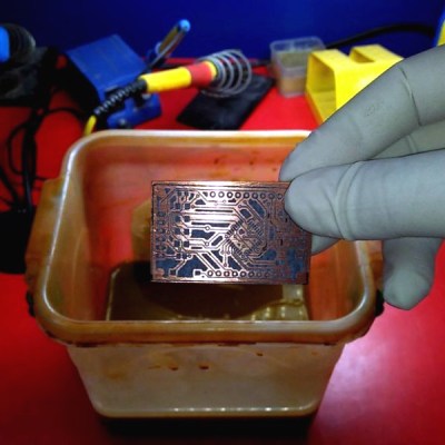
[Pratik Makwana] starts by showing how to design the circuit schematic diagram in an EDA tool (Eagle) and the corresponding PCB layout design. He then uses the toner transfer method and a laminator to imprint the circuit into the copper board for later etching and drilling. The challenging soldering process is not detailed, if you need some help soldering SMD sized components we covered some different processes before, from a toaster oven to a drag soldering process with Kapton tape.

Last but not least, the bootloader firmware. This was done using an Arduino UNO working as master and the newly created the Arduino Nano clone as target. After that you’re set to go. To run an actual sketch, just use your standard USB to UART converter to burn it and proceed as usual.

Voilá, from zero to Nano:

If you still want to build an Arduino but the difficulty level is a bit high for you, maybe a good idea is to start with the Shrimp.


Filed under: Arduino Hacks

In this three part video series we watch [Dirk Herrendoerfer] go from scraps to a nice 3D printed assembly as he iterates through the design of a pen plotter for making circuit boards.

[dana] mentioned [Dirk]’s work in the comments of this post which describes a different process. Many permanent markers stick to copper well enough to last through the chemical etching process. While hand drawing definitely produces some cool, organic-looking boards, for sharp lines and SMDs it gets a bit harder; to the point where it becomes advisable to just let a robot do it.

Of course, [Dirk] was aware of this fact of life. He just didn’t have a robot on hand. He did have some electronic detritus, fishing line, an Arduino, scrap wood, brass tubes, and determination.  The first version‘s frame consisted of wooden blocks set on their ends with holes drilled to accept brass rods. The carriage was protoboard and hot glue. Slightly larger brass tubing served as bushings and guide. As primitive as it was the plotter performed admirably, albeit slowly.

The second version was a mechanical improvement over the first, but largely the same. The software got a nice improvement. It worked better and had some speed to it.

The latest version has some fancy software upgrades; such as acceleration. The frame has gone from random bits of shop trash to a nicely refined 3D printed assembly. Even the steppers have been changed to the popular 28BYJ-48 series. All the files, software and hardware, are available on GitHub. The three videos are viewable after the break. It’s a great example of what a good hacker can put together for practically no money.


Filed under: Arduino Hacks, cnc hacks

[Neumi] has built a CNC Laser using CD-ROM drives as the X and Y motion platforms. The small 405nm laser can engrave light materials like wood and foam. The coolest use demonstrated in the video is exposing pre-coated photo-resist PCBs.

With $61 US Dollars (55 Euro) for the Arduino, stepper drivers, and a laser in the project, [Nuemi] got a pretty capable machine after adding a few parts from the junk bin. He wanted to avoid using existing software in order to learn the concepts behind a laser engraver. In the end, he has a working software package which can send raster scans to an Arduino mega. The mega then controls the sync between the stepper and laser firings. The code is available on GitHub.

The machine can do a 30x30mm PCB in 10 minutes. It’s not about to set a record, but it’s cool and not at all bad for the price. You can see the failed PCBs lined up in the video from the initial tuning, but the final one produced a board very equivalent to the toner transfer method. Video after the break.


Filed under: Arduino Hacks, cnc hacks


  • Newsletter

    Sign up for the PlanetArduino Newsletter, which delivers the most popular articles via e-mail to your inbox every week. Just fill in the information below and submit.

  • Like Us on Facebook