
Oct
03
03
 Daniel Davis wanted to see if he could turn his "dumb" nokia phone and turn it into a smartwatch.
The post Hacking a Nokia Phone into a New Smartwatch appeared first on Make: DIY Projects and Ideas for Makers.
Daniel Davis wanted to see if he could turn his "dumb" nokia phone and turn it into a smartwatch.
The post Hacking a Nokia Phone into a New Smartwatch appeared first on Make: DIY Projects and Ideas for Makers.
The Nokia 3100 is a classic in the circles we frequent. The LCD in this phone is a very cheap and very common display, and it was one of the most popular phones since the phone from Bell, making it a very popular source of cool components.
Now everything is an Internet of Thing, and cellular data for microcontroller projects is all the rage. [Charles] thought it would be interesting to use the famous Nokia 3100 to transmit and receive data. After battling with some weird connectors, he succeeded.
The Nokia 3100 doesn’t have a USB connector, as this phone was made before the EU saved us from a menagerie of cell phone chargers. Instead, this phone has a Nokia Pop-Port, a complex connector that still has TX and RX pins running at 115,200 bit/s 8N1. By fitting a USB socket onto a prototyping board, adding a few level shifters, and connecting the pins in the right order, [Charles] was able to get his Arduino talking to an old Nokia Brick.
[Charles] isn’t quite at the level of sending SMS from his confabulation, and even following a tutorial from [Ilias Giechaskiel] didn’t work. [Charles] is looking for help here, and if you have any suggestions, your input would be appreciated.
There is a problem with using a Nokia 3100 as a cheap Arduino cellular shield: it’s only 2G, and sometime soon those cell towers will be shut down. For now, though, it works, and once those 2G towers are shut down, there are plenty of options with cheap, early Android and iOS phones.


Anyone awake in the early 2000’s knows the familiar shape of those candy bar style mobile phones. In the Shenzhen phone markets we see tons of them. Literally, there are tons of these phone passing through the markets every day. Some are resold while others are disassembled for parts and recycled. This is where all those cheap Nokia 3310/5110 LCD shields come from. It’s great to see so much reuse and recycling.
Having all these cheap LCDs is nice, but most of the interesting and useful parts are wasted. We saw a fantastic opportunity to save a heap of phones from the recycling bin and save people a pocket full of money. We can make a positive impact on the environment if we reuse some of these phones that we are literally tripping over in the streets. Let’s make an Arduino to GSM network bridge for just a few dollars.
Nokia phone Arduino shield – [Link]

by samuel123abc @ instructables.com:
Okay, here’s the deal. There are some tutorials on youtube showing how to get graphics to show on the nokia 5110 and that’s great. If you just want a simple way to do that, go and watch them instead but there are a few problems I see,
1. There are none for mac. I am using a mac and everyone in the videos are using a windows.
2. Sometimes I just wanna go to the computer and search up how to make some graphics. When searching “Nokia 5110 graphics” on google, I found nothing but some libraries and some text.
In this tutorial I will show you how to connect the display, use the code and use some web-based and downloaded tools to create some awesome graphics YOU can customize however you want. Now, enough of me speaking, let’s just begin.
Nokia 5110 graphics tutorial – [Link]
While [Ilias Giechaskiel] was waiting for his SIM900 shield to arrive, he decided to see what he could do with an old Nokia 6310i and an Arduino. He was researching how to send automated SMS text messages for a home security project, and found it was possible to send AT commands via the headphone jack of Motorola phones. But unfortunately Nokia did not support this, as they use a protocol known as FBus. With little information to go on, [Ilias] was able to break down the complicated protocol and take control with his Arduino.
With the connections in place, [Ilias] was able to communicate with the Nokia phone using a program called Gnokii — a utility written specifically for controlling the phone with a computer. Using the Arduino as an intermediary, he was eventually able tap into the FBus and send SMS messages.
Be sure to check out his blog as [Ilias] goes into great detail on how Nokia’s FBus protocol works, and provides all source code needed to replicate his hack. There is also a video demonstration at the end showing the hack in action.

Learn how to use an inexpensive colour LCD shield with your Arduino. This is chapter twenty-eight of our huge Arduino tutorial series.
Updated 03/02/2014
There are many colour LCDs on the market that can be used with an Arduino, and for this tutorial we’re using a relatively simple model available that is available from suppliers such as Tronixlabs, based on a small LCD originally used in Nokia 6100 mobile phones:

These are a convenient and inexpensive way of displaying data, or for monitoring variables when debugging a sketch. Before getting started, a small amount of work is required.
From the two examples we have seen, neither of them arrive fitted with stacking headers (or in Sparkfun’s case – not included) or pins, so before doing anything you’ll need to fit your choice of connector. Although the LCD shield arrived with stacking headers, we used in-line pins as another shield would never be placed on top:

Which can easily be soldered to the shield in a few minutes:

While we’re on the subject of pins – this shield uses D3~D5 for the three buttons, and D8, 9, 11 and 13 for the LCD interface. The shield takes 5V and doesn’t require any external power for the backlight. The LCD module has a resolution of 128 x 128 pixels, with nine defined colours (red, green, blue, cyan, magenta, yellow, brown, orange, pink) as well as black and white.
So let’s get started. From a software perspective, the first thing to do is download and install the library for the LCD shield. Visit the library page here. Then download the .zip file, extract and copy the resulting folder into your ..arduino-1.0.xlibraries folder. Be sure to rename the folder to “ColorLCDShield“. Then restart the Arduino IDE if it was already open.
At this point let’s check the shield is working before moving forward. Once fitted to your Arduino, upload the ChronoLCD_Color sketch that’s included with the library, from the IDE Examples menu:

This will result with a neat analogue clock you can adjust with the buttons on the shield, as shown in this video.
It’s difficult to photograph the LCD – (some of them have very bright backlights), so the image may not be a true reflection of reality. Nevertheless this shield is easy to use and we will prove this in the following examples. So how do you control the color LCD shield in your sketches?
At the start of every sketch, you will need the following lines:
#include "ColorLCDShield.h"
LCDShield lcd;
as well as the following in void setup():
lcd.init(PHILIPS);
lcd.contrast(63); // sets LCD contrast (value between 0~63)
With regards to lcd.init(), try it first without a parameter. If the screen doesn’t work, try EPSON instead. There are two versions of the LCD shield floating about each with a different controller chip. The contrast parameter is subjective, however 63 looks good – but test for yourself.
Now let’s move on to examine each function with a small example, then use the LCD shield in more complex applications.
The LCD can display 8 rows of 16 characters of text. The function to display text is:
lcd.setStr("text", y,x, foreground colour, background colour);
where x and y are the coordinates of the top left pixel of the first character in the string. Another necessary function is:
lcd.clear(colour);
Which clears the screen and sets the background colour to the parameter colour. Please note – when referring to the X- and Y-axis in this article, they are relative to the LCD in the position shown below. Now for an example – to recreate the following display:

… use the following sketch:
// Example 28.1
#include "ColorLCDShield.h"
LCDShield lcd;

void setup()
{
 // following two required for LCD
 lcd.init(PHILIPS);
 lcd.contrast(63); // sets LCD contrast (value between 0~63)
}

void loop()
{
 lcd.clear(BLACK);
 lcd.setStr("ABCDefghiJKLMNOP", 0,2, WHITE, BLACK);
 lcd.setStr("0123456789012345", 15,2, WHITE, BLACK);
 lcd.setStr("ABCDefghiJKLMNOP", 30,2, WHITE, BLACK);
 lcd.setStr("0123456789012345", 45,2, WHITE, BLACK);
 lcd.setStr("ABCDefghiJKLMNOP", 60,2, WHITE, BLACK);
 lcd.setStr("0123456789012345", 75,2, WHITE, BLACK);
 lcd.setStr("ABCDefghiJKLMNOP", 90,2, WHITE, BLACK);
 lcd.setStr("0123456789012345", 105,2, WHITE, BLACK);
 do {} while (1>0);
}
In example 28.1 we used the function lcd.clear(), which unsurprisingly cleared the screen and set the background a certain colour.
Let’s have a look at the various background colours in the following example. The lcd.clear() function is helpful as it can set the entire screen area to a particular colour. As mentioned earlier, there are the predefined colours red, green, blue, cyan, magenta, yellow, brown, orange, pink, as well as black and white. Here they are in the following example:
// Example 28.2

int del = 1000;
#include "ColorLCDShield.h"
LCDShield lcd;
void setup()
{
  // following two required for LCD
  lcd.init(PHILIPS);
  lcd.contrast(63); // sets LCD contrast (value between 0~63)
}

void loop()
{
 lcd.clear(WHITE);
 lcd.setStr("White", 39,40, WHITE, BLACK);
 delay(del);
 lcd.clear(BLACK);
 lcd.setStr("Black", 39,40, WHITE, BLACK);
 delay(del);
 lcd.clear(YELLOW);
 lcd.setStr("Yellow", 39,40, WHITE, BLACK);
 delay(del);
 lcd.clear(PINK);
 lcd.setStr("Pink", 39,40, WHITE, BLACK);
 delay(del);
 lcd.clear(MAGENTA);
 lcd.setStr("Magenta", 39,40, WHITE, BLACK);
 delay(del);
 lcd.clear(CYAN);
 lcd.setStr("Cyan", 39,40, WHITE, BLACK);
 delay(del);
 lcd.clear(BROWN);
 lcd.setStr("Brown", 39,40, WHITE, BLACK);
 delay(del);
 lcd.clear(ORANGE);
 lcd.setStr("Orange", 39,40, WHITE, BLACK);
 delay(del);
 lcd.clear(BLUE);
 lcd.setStr("Blue", 39,40, WHITE, BLACK);
 delay(del);
 lcd.clear(RED);
 lcd.setStr("Red", 39,40, WHITE, BLACK);
 delay(del);
 lcd.clear(GREEN);
 lcd.setStr("Green", 39,40, WHITE, BLACK);
 delay(del);
}
And now to see it in action. In this demonstration video the colours are more livid in real life, unfortunately the camera does not capture them so well.
Now that we have had some experience with the LCD library’s functions, we can move on to drawing some graphical objects. Recall that the screen has a resolution of 128 by 128 pixels. We have four functions to make use of this LCD real estate, so let’s see how they work. The first is:
lcd.setPixel(int colour, Y, X);
This function places a pixel (one LCD dot) at location x, y with the colour of colour.
Note – in this (and all the functions that have a colour parameter) you can substitute the colour (e.g. BLACK) for a 12-bit RGB value representing the colour required. Next is:
lcd.setLine(x0, y0, x1, y1, COLOUR);
Which draws a line of colour COLOUR, from position x0, y0 to x1, y1. Our next function is:
lcd.setRect(x0, y0, x1, y1, fill, COLOUR);
This function draws an oblong or square of colour COLOUR with the top-left point at x0, y0 and the bottom right at x1, y1. Fill is set to 0 for an outline, and 1 for a filled oblong. It would be convenient for drawing bar graphs for data representation. And finally, we can also create circles, using:
lcd.setCircle(x, y, radius, COLOUR);
X and Y is the location for the centre of the circle, radius and COLOUR are self-explanatory. We will now use these graphical functions in the following demonstration sketch:
// Example 28.3

#include "ColorLCDShield.h"
LCDShield lcd;
int del = 1000;
int xx, yy = 0;

void setup()
{
  lcd.init(PHILIPS);
  lcd.contrast(63); // sets LCD contrast (value between 0~63)
  lcd.clear(BLACK);
  randomSeed(analogRead(0));
}

void loop()
{
  lcd.setStr("Graphic Function", 40,3, WHITE, BLACK);
  lcd.setStr("Test Sketch", 55, 20, WHITE, BLACK);
  delay(5000);
  lcd.clear(BLACK);
  lcd.setStr("lcd.setPixel", 40,20, WHITE, BLACK);
  delay(del);
  lcd.clear(BLACK);
  for (int a=0; a<500; a++)
  {
    xx=random(160);
    yy=random(160);
    lcd.setPixel(WHITE, yy, xx);
    delay(10);
  }
  delay(del);
  lcd.clear(BLACK);
  lcd.setStr("LCDDrawCircle", 40,10, WHITE, BLACK);
  delay(del);
  lcd.clear(BLACK);
  for (int a=0; a<2; a++)
  {
    for (int b=1; b<6; b++)
    {
      xx=b*5;
      lcd.setCircle(32, 32, xx, WHITE);
      delay(200);
      lcd.setCircle(32, 32, xx, BLACK);
      delay(200);
    }
  }
  lcd.clear(BLACK);
  for (int a=0; a<3; a++)
  {
    for (int b=1; b<12; b++)
    {
      xx=b*5;
      lcd.setCircle(32, 32, xx, WHITE);
      delay(100);
    }
    lcd.clear(BLACK);
  }
  lcd.clear(BLACK);
  for (int a=0; a<3; a++)
  {
    for (int b=1; b<12; b++)
    {
      xx=b*5;
      lcd.setCircle(32, 32, xx, WHITE);
      delay(100);
    }
    lcd.clear(BLACK);
  }
  delay(del);
  lcd.clear(BLACK);
  lcd.setStr("LCDSetLine", 40,10, WHITE, BLACK);
  delay(del);
  lcd.clear(BLACK);
  for (int a=0; a<160; a++)
  {
    xx=random(160);
    lcd.setLine(a, 1, xx, a, WHITE);
    delay(10);
  }
  lcd.clear(BLACK);
  lcd.setStr("LCDSetRect", 40,10, WHITE, BLACK);
  delay(del);
  lcd.clear(BLACK);
  for (int a=0; a<10; a++)
  {
    lcd.setRect(32,32,64,64,0,WHITE);
    delay(200);
    lcd.clear(BLACK);
    lcd.setRect(32,32,64,64,1,WHITE);
    delay(200);
    lcd.clear(BLACK);
  }
  lcd.clear(BLACK);
}
The results of this sketch are shown in this video. For photographic reasons, I will stick with white on black for the colours.
So now you have an explanation of the functions to drive the screen – and only your imagination is holding you back.
Conclusion
Hopefully this tutorial is of use to you. and you’re no longer wondering “how to use a color LCD with Arduino”. They’re available from our tronixlabs store. And if you enjoyed this article, or want to introduce someone else to the interesting world of Arduino – check out my book (now in a third printing!) “Arduino Workshop”.

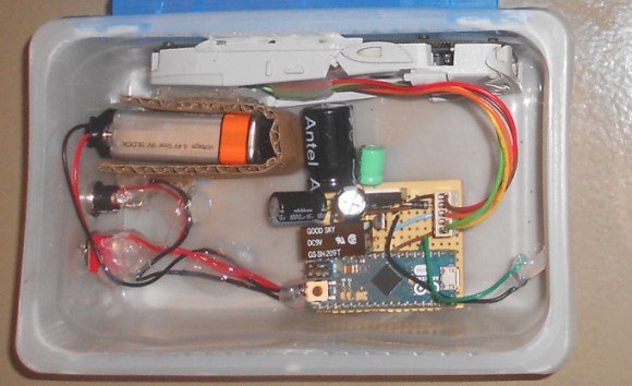
When the power went out at his parents’ shop and ruined the contents of their fridge, [Lauters Mehdi] got to work building a custom power failure alert system to prevent future disasters. Although some commercial products address this problem, [Lauters] decided that he could build his own for the same cost while integrating a specific alert feature: one that fires off an SMS to predefined contacts upon mains power failure.
The first step was to enable communication between an Arduino Micro and a Nokia cell phone. His Nokia 3310 uses FBus protocol, but [Lauters] couldn’t find an Arduino library to make the job easier. Instead, he prototyped basic communication by running an Arduino Uno as a simple serial repeater to issue commands from the computer directly to the phone, and eventually worked out how to send an SMS from the ‘duino. [Lauters] then took the phone apart and tapped into the power button to control on/off states. He also disconnected the phone’s battery and plugged it into an attached PCB. The system operates off mains power but swaps to a 1000mAH 9V backup battery during a power outage, logging the time and sending out the SMS alerts. A second message informs the contacts when power has been restored.
Head over to [Lauters's] project blog for schematics and photos, then see his GitHub for the source code. If you want to see other SMS hacking projects, check out the similar build that keeps a remote-location cabin warm, or the portable power strip activated by SMS.

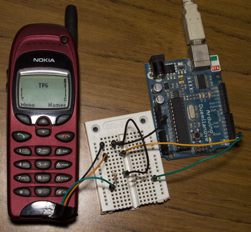
It’s always nice to see how creative makers approach communication issues in DIY projects, and today we would like to highlight the approach followed by Alex, from InsideGadgets.
On his website, he provides a detailed tutorial on how to use an old Nokia 6110 (or any derivatives) to send SMS messages by exploiting the Nokia’s F-bus, a simple bi-directional and full-duplex serial protocol.
After considerable reverse engineering work, made possible by useful online documentation, Alex finally managed to send a SMS from his Arduino board, connected to the phone, thanks to AVR libraries made available by AVRFreaks.
More information can be found on InsideGadget.
[Via: Inside Gadgets]
Planet Arduino is, or at the moment is wishing to become, an aggregation of public weblogs from around the world written by people who develop, play, think on Arduino platform and his son. The opinions expressed in those weblogs and hence this aggregation are those of the original authors. Entries on this page are owned by their authors. We do not edit, endorse or vouch for the contents of individual posts. For more information about Arduino please visit www.arduino.cc
You are currently browsing the archives for the nokia category.
 Arduino Blog Make Magazine Blog Hackaday Electronics-Lab Noel Portugal CNX-Software Matthew Rollings Chris Debenham Techatronic Giasone John Boxall Arduino++ Adafruit Blog EngineeringException Mamaus's Blog Tinker Hobby Bits and Pieces Wayne and Layne NerdyTechy Liudr's Blog Steve Marple b7arduino Chipwired Embedded-Lab