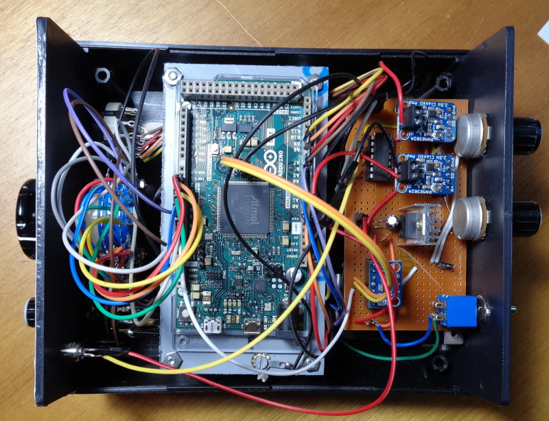
[JanHerman] knows that tuning musical instruments is all about precision and that precision is measured in a logarithmic unit called a cent. A cheap tuner unit might be accurate to 1.5 cents which sounds good until you look at one for ten times the price and find it is accurate to 0.1 cents. So you can spend $800 for precision or $60 for something less. [Jan] decided to build something better and cheaper using a 32-bit Arduino and a DDS frequency generator chip on a breakout board.
Oddly enough, the device doesn’t have a display. Instead, it generates a precise frequency and couples it to the piano using a transducer. You tune the string to the corresponding note. The post has a lot of detail about how piano tuning works.
If you know about the chromatic scale, the equal temperament system, and how many cents are in an octave, you might want to skip the first section. We didn’t though. If we learned any of that in childhood piano classes, we’ve forgotten it.
For those whose quest for precision isn’t that critical, note that the difference between two notes can be as little as 0.3316 Hz. It is interesting that the final design isn’t the first one [Jan] attempted and there is an explanation of why the first design wasn’t successful.
The final design calls for a 24-position rotary switch which is tough to find. We might have opted for a rotary encoder and a display or even some LEDs to make a cheap alternative. As it was, the cheap switch used caused problems and required a replacement and very careful soldering.
Somehow [hvde] wound up with a CB radio that does AM and SSB on the 11 meter band. The problem was that the radio isn’t legal where he lives. So he decided to change the radio over to work on the 6 meter band, instead.
We were a little surprised to hear this at first. Most radio circuits are tuned to pretty close tolerances and going from 27 MHz to 50 MHz seemed like quite a leap. The answer? An Arduino and a few other choice pieces of circuitry.
In particular, [hvde] removed much of the RF portion of the radio, leaving just the parts that dealt with the intermediate frequency at 7.8 MHz. Even the transmitter generates this frequency because it is easier to create an SSB signal at a fixed frequency. The Arduino drives a frequency synthesizer and an OLED display. A mixer combines the IF signal with the frequency the Arduino commands.
The radio had a “clarifier” which acts as a fine tuning control. With the new setup, the Arduino has to read this, also, and make small adjustments to the frequency. The RF circuits in the radio took some modifications, too. It is all documented, although we will admit this probably isn’t a project for the faint of heart.
There’s a lot more to learning how to play the guitar than just playing the right notes at the right time and in the right order. To produce any sound at all requires learning how to do completely different things with your hands simultaneously, unless maybe you’re a direct descendant of Eddie Van Halen and thus born to do hammer ons. There’s a bunch of other stuff that comes with the territory, like stringing the thing, tuning it, and storing it properly, all of which can be frustrating and discouraging to new players. Add in the calluses, and it’s no wonder people like Guitar Hero so much.
In an interesting departure from standard stringed instrument construction, plucking is isolated from fretting. The player fingers notes on four strings but plucks a special, fifth string with a conductive pick that closes the plucking circuit. By contrast, the fretting strings are normally high. When pressed, they contact the foil-covered fingerboard and the circuit goes low. All five strings are made of carbon-impregnated elastic and wrapped with 30AWG copper wire.
All five strings connect to an Arduino UNO and then a laptop. The laptop sends the signal to a Bluefruit friend to change Bluetooth to UART in order to satisfy the PIC32. From there, it goes out via 2-channel DAC to a pair of PC speakers. One channel has the string tones, which are generated by Karplus-Strong. To fill out the sound, the other DAC channel carries undertones for each note, which are produced by sine tables and direct digital synthesis. There’s no cover charge; just click past the break to check it out.
Hackaday reader [Jan Ostman] has been making microcontroller-based DIY synthesizers for quite a while now. Recently, he’s opened up the source for a lot of them so that you can play along at home. All of these virtual-analog synths and soundmakers can be realized on an Arduino or AVR ATmega328 if you happen to have one lying around.
Extra parts like a keyboard, some pushbuttons, or some potentiometer knobs to twiddle won’t hurt if you’d like to make something more permanent or more obviously playable, like [Jan] does. On the other hand, if you’d just like to get your feet wet, I’ve tweaked his code to be more immediately plug-and-play. The code is straightforward enough that it’s a good learning platform. So let’s take a quick tour through three drum machines and a string synth, each of which you can build on a breadboard in just a few minutes.
To install on an Arduino UNO, fetch the zip file from this GitHub repository, and move each subfolder to your Arduino sketch directory. You’re ready to play along.
Simple Drum Machines
[Jan] has two sample-playback~based drum machines that he’s published the code for: the dsp-D8 with straight-ahead drum samples and the dsp-L8 loaded with Latin percussion. They’re essentially the same code base, but with different samples, so we’ll treat them together.
Working through [Jan]’s code inspired me to write up a longer article on DDS playback, so if you want to brush up on the fundamentals, you can head over there. The short version is that you can change the pitch of playback of a sample by using a counter that’s much larger than the number of data points you’re going to play.
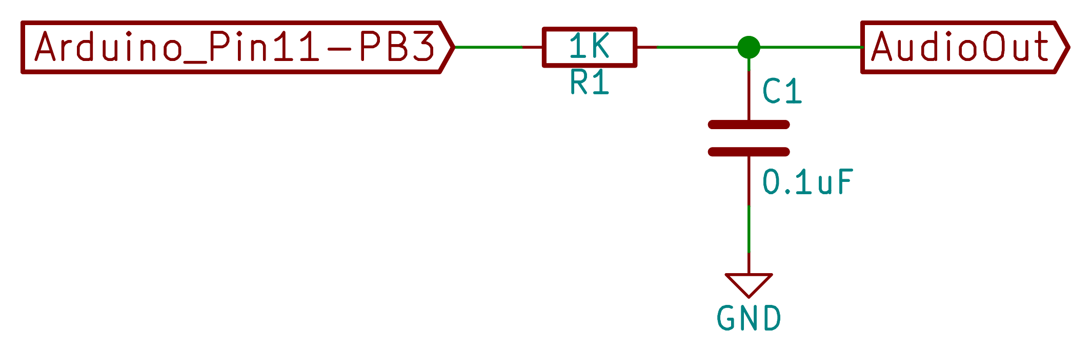
[Jan]’s drum machines all use the AVR’s hardware pulse-width modulation (PWM) peripherals to play the samples back out. You could use something fancier, but this gets the job done with just an optional resistor and capacitor filter on the output, bringing the total parts count to three: Arduino, 1 KOhm resistor, and a decent-sized (0.1 uF?) capacitor. An interrupt service routine (ISR) periodically loads a new sample value into the PWM register, and the AVR’s peripheral hardware takes care of the rest.
One nice touch is the use of a circular buffer that holds the playback sample values until the ISR is ready for them. In the case of the drum machines, there’s not much math for the CPU to do — it just combines the samples from all of the different simultaneous voices — but in his more complicated modules this buffer allows the CPU to occasionally take more time to calculate a sample value than it would otherwise have between updates. It buys [Jan]’s code some breathing room and still allows it to make the sample-playback schedule without glitching.
[Jan] adds individual pitch control for each sample, which is great for live playing or tweaking, and you can watch him use them in his two videos: one for the dsp-D8 and another for the dsp-L8. Wiring up so many knobs is a breadboard-salad, though, so I’ve gone through the code for you with a fine-toothed chainsaw, and hacked off [Jan]’s button-and-knob interface and replaced it with the Arduino’s built-in serial I/O.
To play my version of [Jan]’s drum machines, each sample is mapped to a key in the home row: “asdfjkl;”. If you’ve got a proper serial terminal program that transmits each keystroke in real-time, you’ll be tapping out rhythms at 9600 baud in no time. Note that the Arduino IDE’s built-in terminal only sends the keystroke after you hit “enter” — this makes playing in tempo very difficult. (I use screen /dev/ttyACM0 9600 or the terminal that’s built-in with Python’s pyserial library myself. What do Windows folks use for a real-time terminal?)
If you haven’t already, download this zip file, move each sub-folder to your Arduino sketch directory, and connect an amplified speaker either directly to your Arduino’s pin 11 and ground, or include an RC filter. It’ll only take a second before you’re playing. When you want the full version with all the knobs, head on over to [Jan]’s site.
O2 Minipops
[Jan]’s O2 Minipops machine mimics an old-school rhythm box: the Korg mini pops 7. Whether this primitive drum machine is horribly cheesy or divinely kitschy is in the ear of the beholder, but it’s a classic that has been used all over. [Jan]’s named his after an epic album Oxygene by Jean-Michel Jarre. You’ll hear them starting around 1:40 into the clip. Jarre famously used to press multiple buttons on the Minipops, making more complex drum patterns by playing more than one at a time.
The nice thing about having your own Minipops in firmware is that you can add the features you want to it. Instead of having to mash down multiple plastic buttons live on stage like poor Mr. Jarre, you can just tweak the firmware to suit. Need longer patterns? You’ve got the RAM. Emphasis? Swing? Tap tempo? It’s all just a matter of a few lines of code.
The sound playback code is just like the simpler drum machines above, so we won’t have to cover that again. The only real addition is the sequencer, but that’s where the real magic lies. After all, what’s a drum machine without some beats? Because there are eight possible drum sounds, each beat is a byte and so four bars of 4/4 time is just sixteen bytes stored in memory. I broke the data out into its own header file O2_data.h, so have a look there for the pre-programmed rhythms, and feel free to modify them to suit your own needs.
In order to make the O2 Minipops immediately playable, I stripped out the potentiometer code again (sorry [Jan]!) and passed off control over the serial port. The “user interface” has five controls. Press j and k to switch between patterns and f and d to speed up or slow down. (They’re under your first two fingers in the home row.) The space bar starts and stops the drum machine.
Try switching between the patterns on the fly with j and k — it’s a surprisingly fun way to create your own, slightly less cheesy, patterns. You need to download this code and give it a try. Trust me.
[Jan]’s Solina is a “virtual analog” in the sense that it builds up sawtooth waveforms in the microcontroller’s RAM and then outputs the corresponding voltage through PWM. And that’s a good start for a string synthesizer, because a filtered sawtooth waveform is a good first stab at the sound put out by a violin, for example.
Solina — the clone
The secret to the sound of the string section of an orchestra (and to string synthesizers that mimic it) is that it’s a combination of many different bowed instruments all playing at once. No matter how precise the players, they’re each slightly differently tuned, and none of the strings are resonating exactly in phase. The Solina mimics this by detuning each oscillator, naturally, and by moving them in and out of phase with each other. If you want to dig into the details of how exactly [Jan]’s Solina works, he explains it well in this blog post.
Again, I’ve converted it for direct-serial control, and you can control the envelope, detune, LFO speed, and modulation depth over the serial port. Press the spacebar once to simulate a keypress, and again to let go. Try the Solina with detune and pitch modulation around twenty, and play with the LFO rate and other parameters. That’s a lot of useful noise for just some sawtooth waves.
Keyboards and What’s Next
[Jan]’s builds are much more than what we’re demonstrating here, of course. His blog kicks off (in 2009!) with a project that essentially shoe-horns a PC into a keyboard enclosure, and the Solina and others get their own keys too. We’ve just presented the kernel of any such project — there’s a lot of labor-of-love left in wiring up all of the diodes necessary to do detection on a keyboard matrix, to say nothing of building enclosures, wiring up potentiometers, and making nice-looking front panels. But if you want to start down that path, you’ve at least got a good start.
[Jan]’s current project is the Minimo miniature monophonic synth that takes the Solina a step further and adds a lowpass filter with (digital) resonance to it. The resulting sounds are great, so we’re excited to see where [Jan] takes this one in the future.
Thanks again, [Jan], for opening the code up. And if any of you build something with this, be sure to post in the comments and let us all know. Since I started playing around with these, I’ve got the hankering to modularize the code up a bit and make it into something that’s even easier to adapt and modify. Maybe we’ll have to start up a Hackaday.io project — these little simple synths are just too much fun!
If you are a hacker, you might consider ham radio operators as innovative. Most people, however, just see them as cheap. So it is no surprise that hams like [jmharvey] will build an antenna analyzer from a DDS module and an Arduino instead of dropping a few hundred dollars on a commercial unit. As he points out, you probably only need an analyzer for a day or two while you set up an antenna. Unless you are a big time antenna builder, the unit will then sit idle on the shelf (or will wind up on loan to hams even cheaper than you are).
The design is rooted in another proven design, but changed to take advantage of parts he happened to have on hand. Although the build is on a universal circuit board, [jmharvey] used Eagle to lay out the circuit as though it were a PCB. Since placement can be important with an RF circuit, this isn’t a bad idea. It’s always easier to move stuff around on the screen than on the perf board.
Since this is a no frills, unit, you are expected to grab the output from the Arduino and manually put it in a spreadsheet to plot the results. There is another version of the Arduino code that drives an OLED screen, although you still need a PC to kick the process off. One interesting feature of the Arduino code is how it deals with the nonlinear nature of the diodes used in the circuit. After plotting the values with known loads, [jmharvey] broke the diode operation into three regions and used different equations for each region. Even so, he warns that readings higher than 1:1 VSWR are only accurate to 10% or 20% – still good enough for ham shack use.
If you want an antenna analyzer for $40 (or less, if you have a good stock of parts) this looks like a worthwhile project. If, however, you want to repurpose it to Rickroll your neighbor’s AM radio, you might want to go with the commercial unit.
Click past the break to see the analyzer in action.
DuWayne (KV4QB) has done something very cool here. He’s taken an Arduino Nano, a cheap AD9850 DDS board, a small screen, and a couple of log detectors, and he has built IN AN ALTOIDS TIN a scalar network analyzer that lets you see the bandpass of a filter. (We posted an earlier version of this here: http://soldersmoke.blogspot.com/2015/01/duwaynes-ad9850-arduino-tft-swr-scanner.html ) Wow. I’ve been doing this by hand, changing the input freq at 100Hz increments, measuring the output, putting the results into a spread sheet, converting to log (db), creating a graph… DuWayne makes it a lot easier. DuWayne is being encouraged to write up the results, possibly for QRP Quarterly.
Scalar Network Analyzer – In an Altoids Tin - [Link]
There has been a lot of talk lately about inexpensive DDS (direct digital synthesis) function generators, and I always enjoy a kit – so it was time to check out the subject of this review. It’s the “FG085 miniDDS function generator” from JYE Tech. JYE is a small company in China that makes inexpensive test equipment kits, for example their capacitance meter (my first kit review!) and DSO. The capacitance meter was good, the DSO not so good – so let’s hope this is better than their last efforts.
Assembly
The instructions (AssemblyGuide_085G) are much better than previous efforts, and if you have bought the kit – read them. The kit arrives in a large zip-lock bag, with the following bundle of parts:
The AC adaptor is 100~240V in, 15V DC out. Everything is included with the kit including a short BNC to alligator clips lead for output. The PCBs are very good, with a nice solder mask and silk screen:
and back:
At this point we realise that most of the work is already done. There’s two microcontrollers ATmega48 and ATmega168- one for display and user-interface control, and the other for function generation. It takes only a few minutes to solder in the through-hole parts, headers and sockets:
… then you flip over the PCB and add the LCD:
… followed by the buttons and rotary encoder. From previous research this is the part that causes people a lot of trouble – so read carefully. There’s a lot of buttons – and if they aren’t inserted into the PCB correctly your life will become very difficult. The buttons must be inserted a certain way – they’re “polarised” – for example:
As you can see above, one side has a double-vertical line and the other side has a single. When you fit the buttons to the PCB – the side with the double-vertical must face the left-hand side of the PCB – the side with the DC socket. For example:
Furthermore, don’t be in a rush and put all the buttons in then try to solder them all at once. Do them one at a time, and hold them tight to the PCB with some blu-tac or similar. If they don’t sit flush with the PCB the front panel won’t fit properly and the buttons will stick when in use. So exercise some patience, and you’ll be rewarded with an easy to use function generator. Rush them in and you’ll be very unhappy. I warned you! After fitting each button, test fit the front panel to check the alignment, for example:
Then you end up with nicely-aligned buttons:
… which all operate smoothly when the panel is fitted:
After the buttons comes the rotary encoder. Be very careful when fitting it to the PCB – the data legs are really weak, and bend without much effort. If you push in the encoder, be mindful of the legs not going through the holes and bending upwards. Furthermore, when soldering in the encoder note that you’re really close to an electrolytic – you don’t want to stab it with a hot iron:
The CP2012 chip in the image above is for the USB interface. More on that later. Now the next stage is the power-test. Connect DC power and turn it on – you should be greeted by a short copyright message followed by the operation display:
If you didn’t – remove the power and check your soldering – including the capacitor polarities and look for bridges, especially around the USB socket. Now it’s time to fit the output BNC socket. For some reason only known to the designers, they have this poking out the front of the panel for the kit – however previous revisions have used a simple side-entry socket. Thus you need to do some modifications to the supplied socket. First, chop the tag from the sprocket washer:
… then remove the paper from the front panel:
Now solder a link to the washer in a vertical position:
… then fit the BNC socket to the panel, with the washer aligned as such:
Finally, align the top panel with the PCB so the BNC socket pin and washer link drop into the PCB and solder them in:
If you want to use the servo mode, solder three short wires that can attach to a servo form the three “output” pads between the BNC and USB socket.
Finally, screw in the panels and you’re finished!
Using the function generator
Operation is quite simple, and your first reference should be the manual (manual.pdf). The display defaults to normal function generator mode at power-up – where you can adjust the frequency, offset, amplitude and type of output – sine, square, triangle, ramp up, ramp down, staircase up and down:
The ranges for all functions is 0~10 khz, except for sine which can hit 200 kHz. You can enter higher frequencies, such as up to 250 kHz for sine – but the results aren’t so good.
Instead of filling this review with lots of screen dumps from an oscilloscope to demonstrate the output – I’ve made the following video where you can see various functions being displayed on a DSO:
You can also create signals to test servos, with adjustable pulse-width, amplitude and cycle times. However you’ll need to solder three wires onto the PCB (next to the BNC socket area) to attach to the servo.
According to the user manual and various retailers’ websites – the FG085 can generate frequency sweeping signals. These are signals that sweep from a start to as finish frequency over a period of time. However the firmware on the supplied unit is old and needs updating to enable this function. You can download the firmware in .hex file format from here. Then go and dig up an AVR programmer and avrdude. At the time of writing we had some issues with the signature not being recognised when updating the firmware, and solidly bricked the FG085. Our fault – so when that’s sorted out we’ll update the review – stay tuned.
There is also a USB port on the side – after installing CP2102 drivers in Windows we could connect at 115200 bps with terminal, however all the FG085 returned was the firmware version number. Perhaps later on the designers will update the firmware to allow for PC control. Somehow I wouldn’t bank on it.
Oh – if you’re wondering what DDS is - click here!
Conclusion
It’s an interesting piece of equipment. Putting the firmware upgrade issues to one side, the FG085 does what it sets out to do. During testing it worked well, and we didn’t come across any obvious inaccuracies during use. The price varies between US$43 and $50 – so for that money it’s a good kit. Just take care during construction and you’ll be fine.
The function generator is available in kit form or assembled, with or without panels from China. The kit version with panels is also available from Sparkfun (KIT-11394) and their resellers. Full-sized images available on flickr. This kit was purchased and reviewed without notifying the supplier.
In the meanwhile have fun and keep checking into tronixstuff.com. Why not follow things on twitter, Google+, subscribe for email updates or RSS using the links on the right-hand column? And join our friendly Google Group – dedicated to the projects and related items on this website. Sign up – it’s free, helpful to each other – and we can all learn something.
Planet Arduino is, or at the moment is wishing to become, an aggregation of public weblogs from around the world written by people who develop, play, think on Arduino platform and his son. The opinions expressed in those weblogs and hence this aggregation are those of the original authors. Entries on this page are owned by their authors. We do not edit, endorse or vouch for the contents of individual posts. For more information about Arduino please visit www.arduino.cc
You are currently browsing the archives for the dds category.