Posts | Comments

Planet Arduino

Archive for the ‘mega’ Category

Fans off Wallace and Gromit will all remember two things about the franchise: the sort of creepy — but mostly delightful — stop-motion animation and Wallace’s Rube Goldberg-esque inventions. YouTuber Gregulations was inspired by Wallace’s Autochef breakfast-cooking contraption and decided to build his own robot to prepare morning meals.

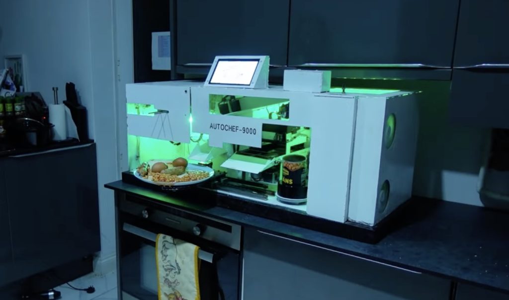
Gregulations wanted his Autochef-9000 to churn out traditional full British breakfasts consisted of buttered toast, eggs, beans, and sausage. That was an ambitious goal, because each of those foods requires several steps to prepare. Gregulations’ solution was to, essentially, create one large machine that contains several smaller CNC machines. Each one is distinct and tailored to suit a particular food. In total — if you add up all of the different sections — this is a 12-axis CNC machine.

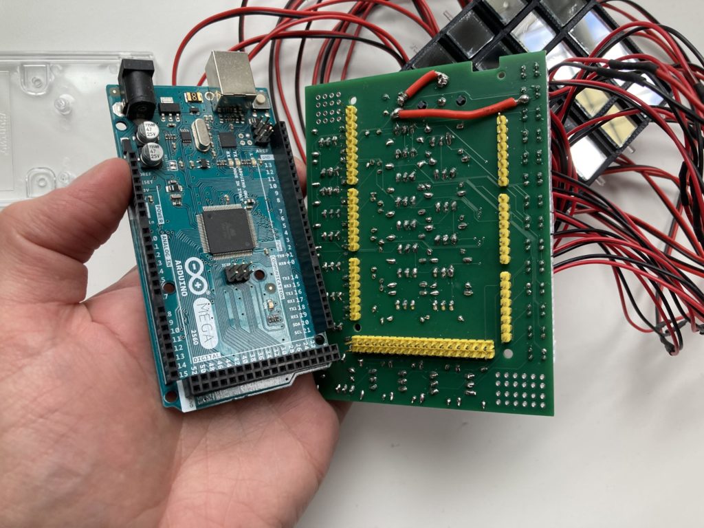
The Autochef-9000’s central controller is an Arduino Mega 2560 board. But even with the power and number of pins available, that wouldn’t have been able to handle everything. So it divvies out some tasks to Arduino UNO Rev3 boards.

As you would expect, this takes quite a lot of heat to cook everything. That’s why the Autochef-9000 contains several electric heating elements, which the Arduinos control via relays.

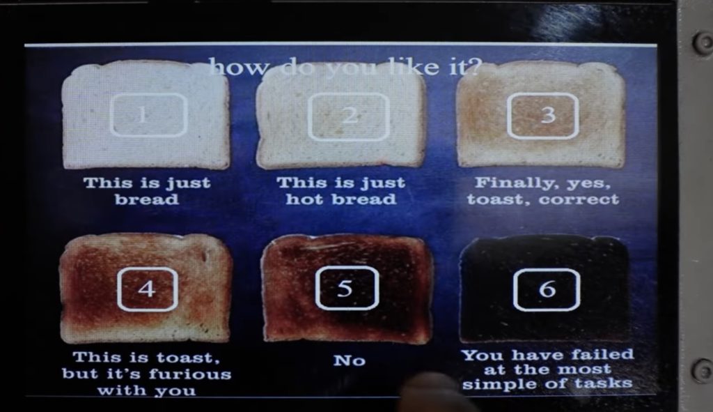
Users can order food using a touchscreen menu system or a smartphone interface. Autochef-9000 will then whir to life. It will open and heat a tin of beans, grab and heat a sausage, hard boil an egg, and toast and then butter bread fed from a magazine. Finally, it will deposit all of those items onto a plate.

There is a lot going on inside of this machine and Gregulations breezes past a lot of the technical details, but it is a joy to see in action. And unlike Wallace’s inventions, this one hasn’t caused any serious disasters (yet).

The post Autochef-9000 can cook an entire breakfast automatically appeared first on Arduino Blog.

Do you really understand what is happening within the mysterious black packaging of a microcontroller or microprocessor? Most people don’t — we just learn how to use them. That’s because they’re wildly complex circuits combining many different subsystems that are all abstracted away from the view of the user. To help students better understand these integrated circuits (ICs), Dr. Panayotis Papazoglou designed the Hardware-Oriented Microprocessor Simulator (HOMS)

Dr. Papazoglou is an associate professor at the National and Kapodistrian University of Athens (NKUA), so he has a stake in creating an educational tool like this one. The goal of HOMS is to provide a visual and tactile demonstration of what happens inside an eight-bit microprocessor. For example, it will show a value moving from a counter to a memory register. That’s something that is difficult to visualize when using a microprocessor, even if you’re working close to “the metal” in assembly. 

HOMS is a modular system, so students can experiment with blocks that represent different subsystem circuits within a microprocessor. Each module has an Arduino UNO Rev3 board to control its own functions, with all of the modules working under the coordination of a central Arduino Mega 2560 controller. One module may, for instance, represent memory and will show the data “written” to it on a display. Another module may have buttons and switches to allow user input.

There are software simulation tools that seek to illustrate computing fundamentals in a similar way, but many people learn better through physical interaction. For those people, HOMS could be very helpful.

The post The Hardware-Oriented Microprocessor Simulator illustrates the inner workings of microcontrollers appeared first on Arduino Blog.

Robots come in all shapes and sizes, but one of the most popular styles for industrial applications is the SCARA (Selective Compliance Assembly Robot Arm). These have multiple degrees of freedom, each of which rotates around the vertical Z axis. But they’re otherwise constrained, which can have advantages for certain applications. For example, they tend to have relatively high payload capacities. If you’re on a budget but want to dip your toes in, tuenhidiy’s SCARA plotter is a great way to start.

This is a follow-up to tuenhidiy’s previous SCARA design from a couple of years ago. The new version is more robust and includes a homing feature, which is important for repeatability. This is set up as a plotter and the firmware reflects that, but it would be possible to adapt the mechanical design for other purposes. 

To keep costs down, most of the structure is PVC pipe. Stepper motors provide actuation via GT2 timing belts and pulleys. An Arduino Mega 2560 board controls those steppers through a RAMPS 1.4 board with A4988 stepper drivers. An interface module with a 2004 LCD, rotary encoder, buzzer, and button lets the user start jobs.

In this case, those jobs are G-code files containing the movement commands to reproduce the drawings. That works because the Arduino runs Marlin firmware (popular in the 3D printing community). The use of Marlin made homing easy and it accepts g-code that users can create with most of the standard software tools. 

The post Building your own affordable SCARA plotter with Arduino appeared first on Arduino Blog.

If you’re heard the pop music emanating from any recent reality TV show, you won’t be surprised to learn that AI is perfectly capable of generating tunes on demand. It won’t replace true artistry any time soon, but AI music fits all of the technical criteria. But typing a prompt is boring, which is why Arvind Sanjeev constructed this gorgeous and imaginative AI synthesizer called SPIN.

SPIN is beautiful and looks like a cross between a turntable and a drum machine. Those visual cues hint at its function. The user can press buttons on the right-side pad to define musical characteristics, which then form a prompt for a language model called MusicGen. That synthesizes music according to the selected characteristics, like “happy” and “lo-fi.” The music then starts playing and the user can control its speed and direction using the record on the turntable — even scratching like a DJ if they want.

A Raspberry Pi 4 Model B runs MusicGen, but it receives inputs through an Arduino Mega 2560 connected to the buttons. There are also dials to set song duration and BPM (beats per minute), as well as control knobs.

The turntable is a Numark PT-01, but the vinyl is a special dummy record that only contains a time code track. The sound from that then feeds through the audio driver back to the Raspberry Pi, where it is decoded to control the playback of the synthesized music. 

SPIN is truly stunning to look at and its functionality is quite interesting, but Sanjeev’s real motivation was to raise awareness about the ethics of AI-generated art and the original human-made art it is trained on. 

The post SPIN is a beautiful and imaginative AI synthesizer appeared first on Arduino Blog.

Proper spindle speed control is necessary to get good CNC milling results. If your spindle speed is inconsistent, your speed and feed calculations will be wrong. That will lead to poor finishes and even broken end mills (and ruined parts) in extreme cases. But cheap CNC mills and routers often have insufficient spindle speed controllers. That’s why Joekutz’s Workbench built an improved spindle speed controller for his generic 3040 CNC mill.

This DIY spindle speed controller has two major improvements: more precise adjustment and closed-loop feedback.

The original controller just had an imprecise potentiometer knob and dot markings, making it impossible to set to a specific speed. The new version lets the user set the spindle to a desired speed with a digital readout.

It also has closed-loop feedback, so it can adjust power to the motor as necessary to maintain the set speed under load. Without that, even a light load could slow down the spindle and throw off the speed/feed balance. 

Joekutz’s Workbench achieved this using an Arduino UNO Rev3 board. It reads input from a rotary encoder to set the motor speed, then shows that speed on a seven-segment display. It controls the motor speed via PWM through a DIY optical isolator, a transistor, and a MOSFET. At the same time, it receives feedback on the real-world motor speed using an LED and photoresistor. That measures the reflectivity of the spinning spindle, which has a piece of aluminum foil tape in one area to increase reflectivity. That lets the Arduino detect a revolution of the motor and calculate the RPM. 

The CNC mill uses an Arduino Mega 2560 with GRBL for controlling the axes’ stepper motors. The Arduino Uno spindle controller can receive g-code speed commands from that, or the user can set the speed using the rotary encoder dial. 

The post Build a better spindle controller for your CNC mill appeared first on Arduino Blog.

Pinball machines are prime examples of the dizzying heights achieved by engineers in the electromechanical era before digital electronics came along. But while those classic pinball machines are extremely impressive from an engineering standpoint, they required an immense amount of expertise and were therefore unapproachable to most. By utilizing modern digital components like Arduino development boards, Barjo was able to construct this amazing Jurassic Park-themed pinball machine.

From a user perspective, this looks and operates a lot like a classic pinball machine. But instead of relying on complex mechanical linkages and vast arrays of electric switches, it takes advantage of today’s microcontrollers and sensors. The table is mostly wood and Barjo 3D-printed a bunch of custom parts, such as the paddles, pathways for the ball, and enclosures for the electronic components. 

Some of the parts, like the spring-loaded ball launcher, are standard off-the-shelf pinball components that are available through retailers that sell refurbishment parts. But most are custom and work using electronic circuitry. The electronic components operate under the control of an Arduino Nano and an Arduino Mega 2560. The Nano is tasked with the flippers, while the Mega handles the displays, sensors, and solenoids.

There are a variety of sensors on the table, such as infrared break beam sensors to detect the passing ball. Those can trigger solenoids to open up gates to specific pathways, like the T-Rex paddock that lets the player rack up additional points. Those points, and some status information, show up on an eight-digit seven-segment display. And, of course, there are plenty of flashing lights to create the ideal pinball experience.

The post This DIY Jurassic Park pinball machine is a T-Rexcellent use of Arduino appeared first on Arduino Blog.

Some of YouTube’s most famous YouTube makers get together every year for a Secret Santa gift exchange. We already showed you the heartbeat-controlled drum machine that Sam Battle built for Ali Spagnola, but what did Battle receive in the gift exchange? Roboticist extraordinaire James Bruton drew Battle and made him this oversized robotic Furby.

Bruton started by skinning a normal Furby to take a look inside and find out how it ticks. The current models are a bit different than the originals from a couple of decades ago, but they’re still pretty simple. There are basic mechanical linkages for the animatronic movement, sensors to detect touch and movement, a speaker for the sound, and cheap LCD eyes. Bruton didn’t reuse any of those components, but this dissection gave him some direction.

With a Furby anatomy lesson under his belt, Bruton designed the scaled-up version with a 3D-printed skeleton. That houses several servo motors to actuate the eyes, eyelids, ears, and mouth, along with two small linear actuators that let it rock back and forth. An Arduino Mega 2560 board controls those motors, as well as a DFRobot DFPlayer Mini MP3 player for the sound effects. An infrared proximity sensor lets the Arduino detect nearby movement, so it can react. Under normal conditions, it just cycles through pre-programmed movement and audio. But if the infrared proximity sensor triggers, the Arduino will switch to something new immediately.

The final step was to cover the giant Furby in its signature fur. Bruton left an opening in the chest where there is a cavity big enough for a normal Furby to reside, complete with LED illumination. That has some concerning implications, but the entire Furby aesthetic skirts the creepy line and so it seems fitting.

The post The best Secret Santa gift in an oversized Furby appeared first on Arduino Blog.

A glockenspiel is a pretty ordinary instrument with a very silly name. Many Westerners will immediately notice the similarities between glockenspiels and xylophones, but there are slight differences in pitch and range. Both are played with mallets and so anyone can hammer out some notes. But playing well is much more difficult, which is why CamsLab built this auto-glockenspiel that plays itself.

CamsLab chose the glockenspiel over other instruments because they wanted an excuse to experiment with solenoids. Compared to string, brass, and wind instruments, a percussion instrument like a glockenspiel is very easy to play by electromechanical means. Each bar is a copper pipe of a specific length calibrated to produce a desired note. Every one of those bars has its own solenoid, which strikes the copper on demand.

An Arduino Mega 2560 board controls those solenoids through FETs (field-effect transistors). Those are necessary because the solenoids each require about 1A of current, which is more than the Arduino can supply through a pin. CamsLab also implemented flyback diodes to prevent damage, since solenoids are inductive loads. Those components and the copper bars mount onto a simple frame made of aluminum extrusion.

CamsLab programmed each note in sequence within the sketch, which is cumbersome. A good alternative would be MIDI control. But even as it is, the auto-glockenspiel sounds great.

The post A glockenspiel that plays itself appeared first on Arduino Blog.

Digital light processing (DLP) devices, which we often see in digital projectors, work by reflecting light off of a two-dimensional array of many thousands — or even millions — of moving mirrors. For that to be practical, each mirror must be microscopic and that makes it very difficult to see and understand the way a DLP device functions. To make that more intuitive, Jon Bumstead scaled up a mirror array to build a “macro” DLP mirror device.

Bumstead’s DLP mirror device only has 25 mirrors arranged in a 5×5 grid, so the resolution is too low to be of any use for displays. But the large size makes this the perfect educational demonstration, because users can easily see how the device operates. Each mirror can pivot to one of two states. The first state angles the mirror so light reflects out to where a lens would be. The second state angles the mirror inwards, so light reflects to where an absorbent pad would be. The first state is an “on” pixel and the second state is an “off” pixel. A real DLP device can switch between states fast enough to create shades of gray and the light would go through filters to introduce color.

Each mirror in the macro DLP device is a square half an inch to a side. Mini push-pull solenoids actuate the mirrors between states and an Arduino Mega 2560 board controls those solenoids through transistors on a custom PCB shield. The frame and mechanical components were 3D-printed to keep costs down.

This device isn’t practical for a display, but it is functional and works great as a tangible illustration of DLP technology. In a hazy room, users can see the reflected rays of light in order to grasp the underlying concept.

The post Macro DLP mirror array scales up a fascinating mechanical structure appeared first on Arduino Blog.


  • Newsletter

    Sign up for the PlanetArduino Newsletter, which delivers the most popular articles via e-mail to your inbox every week. Just fill in the information below and submit.

  • Like Us on Facebook