18
Archive for the ‘camera’ Category
18
09
Serial camera module that captures time-lapse and stop-motion videos plus images to uSD card. Use with any micro like mbed and Arduino.
ALCAM allows any embedded system with a serial interface (UART, SPI or I2C) to capture JPG/BMP images and also to record them right onto an SD card. Also, ALCAM gives you the ability to create time-lapse and stop-motion AVI videos and save them directly to the SD card. All done through a set of simple and well documented serial commands. ALCAM can also capture images and videos though a special pin, without the need to send any commands.
ALCAM-OEM – Serial camera module - [Link]
29
ArTICam Interfaces Game Boy Camera with TI Calculators
arduino, arduino hacks, calculator, camera, classic hacks, game boy, game boy camera, gameboy, ti-84, TiCalc Comments Off on ArTICam Interfaces Game Boy Camera with TI Calculators
[Christopher Mitchell] has given Texas Instruments calculators the ability to capture images through a Game Boy Camera with ArTICam. First introduced in 1998, The Game Boy Camera was one of the first low-cost digital cameras available to consumers. Since then it has found its way into quite a few projects, including this early Atmel AT90 based hack, and this Morse code transceiver.
TI calculators don’t include a Game Boy cartridge slot, so [Christopher] used an Arduino Uno to interface the two. He built upon the Arduino-TI Calculator Linking (ArTICL) Library to create ArTICam. Getting the Arduino to talk with the Game Boy Camera’s M64282FP image sensor turned out to be easy, as there already are code examples available. The interface between the camera sensor and the Arduino is simple enough. 6 digital lines for an oddball serial interface, one analog sense line, power and ground. [Christopher] used a shield to solder everything up, but says you can easily get away with wiring directly the Arduino Uno’s I/O pins. The system is compatible with the TI-83 Plus and TI-84 Plus family of calculators. Grabbing an image is as simple as calling GetCalc(Pic1) from your calculator program.
So, If you have an old calculator lying around, give it a try to enjoy some 128×123-pixel grayscale goodness!
Filed under: Arduino Hacks, classic hacks
13
High power of the UDOO “asks” for usage
arduino, camera, HDMI, LCD, soselectronic.com, UDOO, USB Comments Off on High power of the UDOO “asks” for usage
High power of the UDOO “asks” for usage. One of many occasions to make it is to use various available periphery thus gaining a truly universal platform.
Favorite powerful embedded SBC called UDOO (S975-G000-2100-C2) already found many fans. Maybe also because of its compatibility with the Arduino Due platform (hardware and software) and mainly, it´s possible to connect it with various accessories. Thanks to a wide range of interfaces (USB, Ethernet, bluetooth, WiFi, …) is a connection of periphery flawless, what´s also a case of the 5MPx camera (autofocus).
Despite miniature dimensions this camera provides very decent resolution and speed – for example VGA (640×480) @90fps or 1080p @30fps, or QSXGA (2592×1944) @15fps. Also beneficial is recording of a video in a full 70°field of view (FOV).For a practical usage and application development with UDOO also serves the „Starter kit EU” containing an adapter for the third USB, RTC battery holder, HDMI cable with the UDOO logo, USB/ Micro USB Type B cable, SATA power supply cable, power supply adapter and an 8 GB micro SD card.
Perhaps the biggest “attraction” is the spacious 7“ display KIT LCD 7”–Touch 800×480 px RGB with a capacitive touch panel. By connecting of this display with the UDOO microcomputer, we get a ready-made platform usable to control various processes, with a power, which easily suits to majority of applications. Detailed information about the UDOO can be found in our article: Do you want a microcomputer which will „handle everything“?.

High power of the UDOO “asks” for usage - [Link]
28
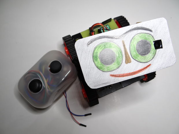
After the Bike Tachometer we posted back in September, Nikus shared with us a new Instructable to show you how to build remote-controlled tank using a first person view (FPV) camera and Arduino Leonardo:
At the beginning I build only RC tank without FPV camera but when I was driving it in the house I have not seen where it is. So I came up with that I will add to it the camera mounted on a 2 servos. The range is about 100m, you can also ride with it at home. With this tank you can see what your cat is doing when you’re not looking. You can see it on a video

Watch it in action and follow the tutorial:
20
A Single Pixel, Color Digital Camera
arduino hacks, camera, digital camera, digital cameras hacks, Radon transform, single pixel, single pixel camera, Software Development Comments Off on A Single Pixel, Color Digital Camera
![]()
[Ben] has written all sorts of code and algorithms to filter, sort, and convolute images, and also a few gadgets that were meant to be photographed. One project that hasn’t added a notch to his soldering iron was a camera. The easiest way to go about resolving this problem would be to find some cardboard and duct tape and built a pinhole camera. [Ben] wanted a digital camera. Not any digital camera, but a color digital camera, and didn’t want to deal with pixel arrays or lenses. Impossible, you say? Not when you have a bunch of integral transforms in your tool belt.
[Ben] is only using a single light sensor that outputs RGB values for his camera – no lenses are found anywhere. If, however, you scan a scene multiple times with this sensor, each time blocking a portion of the sensor’s field of view, you could reconstruct a rudimentary, low-resolution image from just a single light sensor. If you scan and rotate this ‘blocking arm’ across the sensor’s field of view, reconstructing the image is called a Radon transform, something [Ben] has used a few times in his studies.
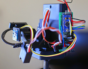 [Ben]‘s camera consists of the Adafruit RGB light sensor, an Arduino, a microSD card, a few servos, and a bunch of printed parts. The servos are used to scan and rotate the ‘blocking arm’ across the sensor for each image. The output of the sensor is saved to the SD card and moved over to the computer for post-processing.
After getting all the pixel data to his laptop, [Ben] plotted the raw data. The first few pictures were of a point source of light – a lamp in his workspace. This resulted in exactly what he expected, a wave-like line on an otherwise blank field. The resulting transformation kinda looked like the reference picture, but for better results, [Ben] turned his camera to more natural scenes. Pointing his single pixel camera out the window resulted in an image that looked like it was taken underwater, through a piece of glass smeared with Vaseline. Still, it worked remarkably well for a single pixel camera. Taking his camera to the great outdoors provided an even better reconstructed scene, due in no small part to the great landscapes [Ben] has access to.
Filed under: Arduino Hacks, digital cameras hacks, Software Development
01
Reverse Engineering a Wireless Studio Lighting Remote
arduino, arduino hacks, camera, Github, Library, lights, nRF24L01+, photo, Photography, radio, radio hacks, remote control, reverse engineer, SPI, strobe Comments Off on Reverse Engineering a Wireless Studio Lighting Remote
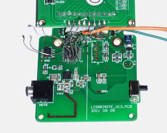
If you want to take a photograph with a professional look, proper lighting is going to be critical. [Richard] has been using a commercial lighting solution in his studio. His Lencarta UltraPro 300 studio strobes provide adequate lighting and also have the ability to have various settings adjusted remotely. A single remote can control different lights setting each to its own parameters. [Richard] likes to automate as much as possible in his studio, so he thought that maybe he would be able to reverse engineer the remote control so he can more easily control his lighting.
[Richard] started by opening up the remote and taking a look at the radio circuitry. He discovered the circuit uses a nRF24L01+ chip. He had previously picked up a couple of these on eBay, so his first thought was to just promiscuously snoop on the communications over the air. Unfortunately the chips can only listen in on up to six addresses at a time, and with a 40-bit address, this approach may have taken a while.
Not one to give up easily, [Richard] chose a new method of attack. First, he knew that the radio chip communicates to a master microcontroller via SPI. Second, he knew that the radio chip had no built-in memory. Therefore, the microcontroller must save the address in its own memory and then send it to the radio chip via the SPI bus. [Richard] figured if he could snoop on the SPI bus, he could find the address of the remote. With that information, he would be able to build another radio circuit to listen in over the air.
Using an Open Logic Sniffer, [Richard] was able to capture some of the SPI communications. Then, using the datasheet as a reference, he was able to isolate the communications that stored information int the radio chip’s address register. This same technique was used to decipher the radio channel. There was a bit more trial and error involved, as [Richard] later discovered that there were a few other important registers. He also discovered that the remote changed the address when actually transmitting data, so he had to update his receiver code to reflect this.
The receiver was built using another nRF24L01+ chip and an Arduino. Once the address and other registers were configured properly, [Richard's] custom radio was able to pick up the radio commands being sent from the lighting remote. All [Richard] had to do at this point was press each button and record the communications data which resulted. The Arduino code for the receiver is available on the project page.
[Richard] took it an extra step and wrote his own library to talk to the flashes. He has made his library available on github for anyone who is interested.
Filed under: Arduino Hacks, radio hacks
01
Reverse Engineering a Wireless Studio Lighting Remote
arduino, arduino hacks, camera, Github, Library, lights, nRF24L01+, Open Logic Sniffer, photo, Photography, radio, radio hacks, remote control, reverse engineer, SPI, strobe Comments Off on Reverse Engineering a Wireless Studio Lighting Remote

If you want to take a photograph with a professional look, proper lighting is going to be critical. [Richard] has been using a commercial lighting solution in his studio. His Lencarta UltraPro 300 studio strobes provide adequate lighting and also have the ability to have various settings adjusted remotely. A single remote can control different lights setting each to its own parameters. [Richard] likes to automate as much as possible in his studio, so he thought that maybe he would be able to reverse engineer the remote control so he can more easily control his lighting.
[Richard] started by opening up the remote and taking a look at the radio circuitry. He discovered the circuit uses a nRF24L01+ chip. He had previously picked up a couple of these on eBay, so his first thought was to just promiscuously snoop on the communications over the air. Unfortunately the chips can only listen in on up to six addresses at a time, and with a 40-bit address, this approach may have taken a while.
Not one to give up easily, [Richard] chose a new method of attack. First, he knew that the radio chip communicates to a master microcontroller via SPI. Second, he knew that the radio chip had no built-in memory. Therefore, the microcontroller must save the address in its own memory and then send it to the radio chip via the SPI bus. [Richard] figured if he could snoop on the SPI bus, he could find the address of the remote. With that information, he would be able to build another radio circuit to listen in over the air.
Using an Open Logic Sniffer, [Richard] was able to capture some of the SPI communications. Then, using the datasheet as a reference, he was able to isolate the communications that stored information int the radio chip’s address register. This same technique was used to decipher the radio channel. There was a bit more trial and error involved, as [Richard] later discovered that there were a few other important registers. He also discovered that the remote changed the address when actually transmitting data, so he had to update his receiver code to reflect this.
The receiver was built using another nRF24L01+ chip and an Arduino. Once the address and other registers were configured properly, [Richard's] custom radio was able to pick up the radio commands being sent from the lighting remote. All [Richard] had to do at this point was press each button and record the communications data which resulted. The Arduino code for the receiver is available on the project page.
[Richard] took it an extra step and wrote his own library to talk to the flashes. He has made his library available on github for anyone who is interested.
Filed under: Arduino Hacks, radio hacks
16
Build an Arduino Yún powered cat camera
arduino, Arduino Yún, camera, cat, tutorial, Yun Comments Off on Build an Arduino Yún powered cat camera
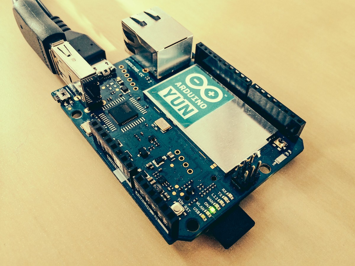
Hotte submitted to our blog a tutorial to monitor his 2 little cats in their favorite spots when he’s at work:
This is a very, very small project that shows just how to build an Arduino Yún powered Camera application: It grabs photos from an USB camera connected to the Yún, saves them periodically on a uSD card and uploads them to a web host where a gallery is automatically created based upon the number of images in the upload folder. This project might be for interest for people that are just getting started with the Yún and want to explore more of its capabilities…
Every 5 minutes the Arduino Yún grabs pictures from a connected USB Webcam and saves it on its micro-SD card. From there the newest photo gets uploaded automatically to this webspace here where a little script transforms all the pictures in one folder to a photo gallery. The optional step adds an PIR motion sensor to get a snapshot if anything moves.
In three simple steps and the help of MJPEG Streamer library for openWRT, you can set it up following the tutorial on this page . And here’s an example of the output:

27
Elinchrom EL-Skyport Triggered by Arduino
arduino hacks, camera, flash, nRF2402G, nRF24L01+, Photography Comments Off on Elinchrom EL-Skyport Triggered by Arduino
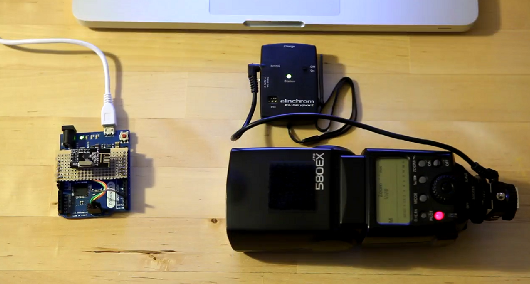
[Toby] has an Elinchrom EL-Skyport, which is a wireless flash trigger. He decided to see if he could trigger it using an Arduino, and came up with a nice proof of concept. This little device was not meant to be user serviceable, as can be seen in what [Toby] uncovered while taking it apart. But once he had it disassembled, he cataloged everything inside, and then he awesomely went to the trouble of drawing up a schematic. With that knowledge, he began reverse engineering the SPI protocol used, which almost deserves an article by itself.
It was a long road to get there, but in the end [Toby] built a prototype Arduino shield that houses an nRF24L01+ module. These are very cheap to pick up on eBay. He gives us the details on hooking up the module, though he had to go through extra hoops since he was using the Arduino Leonardo. Still, once you’re up and running, you can make use of one of the existing libraries specifically for this module.
Thanks to his effort, the rest of us have one more device to hack on. Thanks [Toby]!
Filed under: Arduino Hacks


