[Sigurd] manage to obtain an old vending machine from his dorm. The only problem was that the micocontroller on the main board was broken. He and his friend decided they could most likely get the machine back into working order, but they also knew they could probably give it a few upgrades.
This system uses two Arduino Pro Minis and an Electric Imp to cram in all of the new features. One Arduino is connected to the machine’s original main board. The Arduino interfaces with some of the shift registers, relays, and voltage regulators. This microcontroller also lights up the buttons on the machine as long as that particular beverage is not empty. It controls the seven segment LED display, as well as reading the coin validator.
The team had to reverse engineer the original coin validator in order to figure out how the machine detected and counted the coins. Once they figured out how to read the state of the coins, they also built a custom driver board to drive the solenoids.
A second Arduino is used to read NFC and RFID cards using a Mifare RC522 reader. The system uses its own credit system, so a user can be issued a card with a certain amount of pre-paid credit. It will then deduct credit appropriately once a beverage is vended. The two Arduinos communicate via Serial.
The team also wanted this machine to have the ability to communicate with the outside world. In this case, that meant sending cheeky tweets. They originally used a Raspberry Pi for this, but found that the SD card kept getting corrupted. They eventually switched to an Electric Imp, which worked well. The Arduino sends a status update to the Imp every minute. If the status changes, for example if a beverage was dispensed, then the Imp will send a tweet to let the world know. It will also send a tweet to the maintenance person if there is a jam or if a particular slot becomes empty.
[Oliver] is back with an update to his recent coffee maker hacks. His latest hack allowed him to add a coffee payment system to an off-the-shelf coffee maker without modifying the coffee maker itself. This project is an update to his previous adventures in coffee maker hacking which logged who was using up all of the coffee.
The payment system begins with an Arduino Uno clone inside of a small project enclosure. The Arduino communicates with the coffee maker via serial using the coffee maker’s service port. This port is easily available from outside the machine, so you won’t have to crack open the case and risk voiding your warranty.
The system also includes an RFID reader and a Bluetooth module. The RFID reader allows each user to have their own identification card. The user can swipe their card over the reader and the system knows how many credits are left in their account. If they have enough credit, the machine will pour a delicious cup of coffee.
The Arduino communicates to an Android phone using the Bluetooth module. [Oliver’s] Android app was built using MIT’s app inventor. It keeps track of the account credits and allows the user to add more. The system can currently keep track of up to forty accounts. [Oliver] also mentions that you can use any Bluetooth terminal program to control the system instead of a smart phone app.
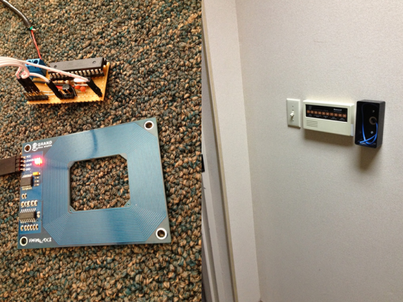
[Shawn] recently overhauled his access control by fitting the doors with some RFID readers. Though the building already had electronic switches in place, unlocking the doors required mashing an aging keypad or pestering someone in an adjacent office to press a button to unlock them for you. [Shawn] tapped into that system by running some wires up into the attic and connecting them to one of two control boxes, each with an ATMega328 inside. Everything functions as you would expect: presenting the right RFID card to the wall-mounted reader sends a signal to the microcontroller, which clicks an accompanying relay that drives the locks.
You may recall [Shawn's] RFID phone tag hack from last month; the addition of the readers is the second act of the project. If you’re looking to recreate this build, you shouldn’t have any trouble sourcing the same Parallax readers or building out your own Arduino on a stick, either. Check out a quick walkthrough video after the jump.
arduino, rfidComments Off on RFID access control for garage door
An Arduino-based RFID access control to open garage door using RFID by Jason Hamilton:
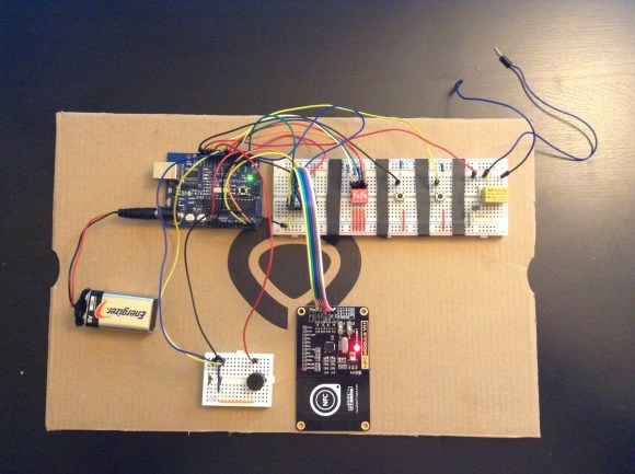
This is my Arduino-based project that allows you to use RFID for access control to open a door. The door can be anything that can be controlled by a relay. In my case it will be a garage door opener.
This is the initial prototype. Next I plan to build it on a prototype shield and then if put it on a PCB. The top section of components (Arduino and breadboard) will be placed inside the garage and the bottom section of components (LED, buzzer, NFC/RFID reader) will be placed outside (in a project box).
[Jason] really wanted to build an RFID controlled garage door opener and decided to turn to Arduino to get the job done. For someone who’s never worked with an Arduino before, he really seemed to know what he was doing.
The Arduino acts as the brains of the operation while an off-the-shelf NFC/RFID reader module is used to read the RFID tags. To add new keys to the system, [Jason] simply swipes his “master” RFID key. An indicator LED lights up and a piezo speaker beeps, letting you know that the system is ready to read a new key. Once the new key is read, the address is stored on an EEPROM. From that point forward the new key is permitted to activate the system.
Whenever a valid key is swiped, the Arduino triggers a relay which can then be used to control just about anything. In this case, [Jason] plans to use it to control his garage door. The system also has a few manual controls. First is the reset button. If this button is held down for two seconds, all of the keys from the EEPROM are erased. This button would obviously only be available to people who are already inside the garage. There is also a DIP switch that allows the user to select how long the relay circuit should remain open. This is configurable in increments of 100ms.
For now the circuit is wired up on a couple of breadboards, but it might be a good idea to use something more permanent. [Jason] could always take it a step further and learn to etch his own PCB’s. Or he could even design a board in Eagle CAD and order a real printed board. Don’t miss the video description of the RFID system below.
Mike Buss used an Arduino Duemilanove, Parallax RFID reader, micro servo, and piezo electric speaker to make a personalized, lockable keepsake box for his girlfriend’s birthday:
The outside of the box is really simple: it just contains a button and an RGB LED. When she presses the button, the LED lights up green or red depending on if the box is locked. When she waves one of the three personalized RFID cards over the box, a little tune plays and the box unlocks.
As part of the project I also did some cool trick with a Pololu pushbutton power switch to make the battery last a lot longer. Since the Arduino is only powered for a few seconds when listening for RFID tags, the battery lasts a lot longer. When the box is finished locking or unlocking (or after a small time delay), it sends a signal to the power switch to turn off the power and conserve battery life. The box has been running on the same 9V battery I put in 4 years ago!
Make an interactive messenger bag that reacts to your RFID-tagged objects with full-color LED animations. It will remind you that your keys or wallet are missing, play custom graphics, or just match your outfit! A great wearable electronics project from MAKE Volume 37.
Learn how to use RFID readers with your Arduino. In this instalment we use an RDM630 or RDM6300 RFID reader. If you have an Innovations ID-12 or ID-20 RFID reader, we have a different tutorial for you.
RFID – radio frequency identification. Some of us have already used these things, and they have become part of everyday life. For example, with electronic vehicle tolling, door access control, public transport fare systems and so on. It sounds complex – but isn’t.
To explain RFID for the layperson, we can use a key and lock analogy. Instead of the key having a unique pattern, RFID keys hold a series of unique numbers which are read by the lock. It is up to our Arduino sketch to determine what happens when the number is read by the lock. The key is the tag, card or other small device we carry around or have in our vehicles. We will be using a passive key, which is an integrated circuit and a small aerial. This uses power from a magnetic field associated with the lock. Here are some key or tag examples:
In this tutorial we’ll be using 125 kHz tags – for example. To continue with the analogy our lock is a small circuit board and a loop aerial. This has the capability to read the data on the IC of our key, and some locks can even write data to keys. Here is our reader (lock) example:
These readers are quite small and inexpensive – however the catch is that the loop aerial is somewhat fragile. If you need something much sturdier, consider the ID20 tags used in the other RFID tutorial.
Setting up the RFID reader
This is a short exercise to check the reader works and communicates with the Arduino. You will need:
Arduino Uno or compatible board and matching USB cable
Simply insert the RFID reader main board into a solderless breadboard as shown below. Then use jumper wires to connect the second and third pins at the top-left of the RFID board to Arduino 5V and GND respectively. The RFID coil connects to the two pins on the top-right (they can go either way). Finally, connect a jumper wire from the bottom-left pin of the RFID board to Arduino digital pin 2:
Next, upload the following sketch to your Arduino and open the serial monitor window in the IDE:
#include <SoftwareSerial.h>
SoftwareSerial RFID(2, 3); // RX and TX

int i;

void setup()
{
  RFID.begin(9600);    // start serial to RFID reader
  Serial.begin(9600);  // start serial to PC
}

void loop()
{
  if (RFID.available() > 0)
  {
     i = RFID.read();
     Serial.print(i, DEC);
     Serial.print(" ");
  }
}
If you’re wondering why we used SoftwareSerial – if you connect the data line from the RFID board to the Arduino’s RX pin – you need to remove it when updating sketches, so this is more convenient.
Now start waving RFID cards or tags over the coil. You will find that they need to be parallel over the coil, and not too far away. You can experiment with covering the coil to simulate it being installed behind protective surfaces and so on. Watch this short video which shows the resulting RFID card or tag data being displayed in the Arduino IDE serial monitor.
As you can see from the example video, the reader returns the card’s unique ID number which starts with a 2 and ends with a 3. While you have the sketch operating, read the numbers from your RFID tags and note them down, you will need them for future sketches.
To do anything with the card data, we need to create some functions to retrieve the card number when it is read and place in an array for comparison against existing card data (e.g. a list of accepted cards) so your systems will know who to accept and who to deny. Using those functions, you can then make your own access system, time-logging device and so on.
Let’s demonstrate an example of this. It will check if a card presented to the reader is on an “accepted” list, and if so light a green LED, otherwise light a red LED. Use the hardware from the previous sketch, but add a typical green and red LED with 560 ohm resistor to digital pins 13 and 12 respectively. Then upload the following sketch:
#include <SoftwareSerial.h>
SoftwareSerial RFID(2, 3); // RX and TX

int data1 = 0;
int ok = -1;
int yes = 13;
int no = 12;

// use first sketch in http://wp.me/p3LK05-3Gk to get your tag numbers
int tag1[14] = {2,52,48,48,48,56,54,66,49,52,70,51,56,3};
int tag2[14] = {2,52,48,48,48,56,54,67,54,54,66,54,66,3};
int newtag[14] = { 0,0,0,0,0,0,0,0,0,0,0,0,0,0}; // used for read comparisons

void setup()
{
  RFID.begin(9600);    // start serial to RFID reader
  Serial.begin(9600);  // start serial to PC
  pinMode(yes, OUTPUT); // for status LEDs
  pinMode(no, OUTPUT);
}

boolean comparetag(int aa[14], int bb[14])
{
  boolean ff = false;
  int fg = 0;
  for (int cc = 0 ; cc < 14 ; cc++)
  {
    if (aa[cc] == bb[cc])
    {
      fg++;
    }
  }
  if (fg == 14)
  {
    ff = true;
  }
  return ff;
}

void checkmytags() // compares each tag against the tag just read
{
  ok = 0; // this variable helps decision-making,
  // if it is 1 we have a match, zero is a read but no match,
  // -1 is no read attempt made
  if (comparetag(newtag, tag1) == true)
  {
    ok++;
  }
  if (comparetag(newtag, tag2) == true)
  {
    ok++;
  }
}

void readTags()
{
  ok = -1;

  if (RFID.available() > 0)
  {
    // read tag numbers
    delay(100); // needed to allow time for the data to come in from the serial buffer.

    for (int z = 0 ; z < 14 ; z++) // read the rest of the tag
    {
      data1 = RFID.read();
      newtag[z] = data1;
    }
    RFID.flush(); // stops multiple reads

    // do the tags match up?
    checkmytags();
  }

  // now do something based on tag type
  if (ok > 0) // if we had a match
  {
    Serial.println("Accepted");
    digitalWrite(yes, HIGH);
    delay(1000);
    digitalWrite(yes, LOW);

    ok = -1;
  }
  else if (ok == 0) // if we didn't have a match
  {
    Serial.println("Rejected");
    digitalWrite(no, HIGH);
    delay(1000);
    digitalWrite(no, LOW);

    ok = -1;
  }
}

void loop()
{
  readTags();
}
In the sketch we have a few functions that take care of reading and comparing RFID tags. Notice that the allowed tag numbers are listed at the top of the sketch, you can always add your own and more – as long as you add them to the list in the function checkmytags() which determines if the card being read is allowed or to be denied.
The function readTags() takes care of the actual reading of the tags/cards, by placing the currently-read tag number into an array which is them used in the comparison function checkmytags(). Then the LEDs are illuminated depending on the status of the tag at the reader. You can watch a quick demonstration of this example in this short video.
Conclusion
After working through this chapter you should now have a good foundation of knowledge on using the inexpensive RFID readers and how to call functions when a card is successfully read. For example, use some extra hardware (such as an N-MOSFET) to control a door strike, buzzer, etc. Now it’s up to you to use them as a form of input with various access systems, tracking the movement of people or things and much more.
And if you enjoyed the tutorial, or want to introduce someone else to the interesting world of Arduino – check out my book (now in a third printing!) “Arduino Workshop” from No Starch Press.
In the meanwhile have fun and keep checking into tronixstuff.com. Why not follow things on twitter, Google+, subscribe for email updates or RSS using the links on the right-hand column? And join our friendly Google Group – dedicated to the projects and related items on this website. Sign up – it’s free, helpful to each other – and we can all learn something.
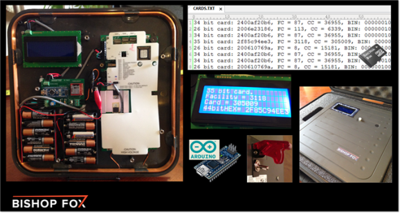
Security researcher [Fran Brown] sent us this tip about his Tastic RFID Thief, which can stealthily snag the information off an RFID card at long range. If you’ve worked with passive RFID before, you know that most readers only work within inches of the card. In [Fran's] DEFCON talk this summer he calls it the “ass-grabbing method” of trying to get a hidden antenna close enough to a target’s wallet.
His solution takes an off-the-shelf high-powered reader, (such as the HID MaxiProx 5375), and makes it amazingly portable by embedding 12 AA batteries and a custom PCB using an Arduino Nano to interpret the reader’s output. When the reader sees a nearby card, the information is parsed through the Nano and the data is both sent to an LCD screen and stored to a .txt file on a removable microSD card for later retrieval.
There are two short videos after the break: a demonstration of the Tastic RFID Thief and a quick look at its guts. If you’re considering reproducing this tool and you’re picking your jaw off the floor over the price of the reader, you can always try building your own…
Planet Arduino is, or at the moment is wishing to become, an aggregation of public weblogs from around the world written by people who develop, play, think on Arduino platform and his son. The opinions expressed in those weblogs and hence this aggregation are those of the original authors. Entries on this page are owned by their authors. We do not edit, endorse or vouch for the contents of individual posts. For more information about Arduino please visit www.arduino.cc
You are currently browsing the archives for the rfid category.