Posts | Comments

Planet Arduino

Archive for the ‘solar’ Category

ESP32-S3 PowerFeather

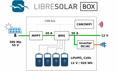
The ESP32-S3 PowerFeather board is an Adafruit Feather-shaped ESP32-S3 WiFi and BLE IoT board that can be powered by a Li-Ion or LiPo battery and supports up to 18V DC input for direct connection to a solar panel. The developer told CNX Software that the main differentiating factor from other ESP32-S3 development boards was “its extensive power management and monitoring features” with a wide DC input range, supply and battery monitoring, and battery protection features. ESP32-S3 PowerFeather specifications: ESP32-S3-WROOM-1-N8R2 MCU – ESP32-S3 dual-core Tensilica LX7 up to 240 MHz with 512KB SRAM, 16 KB RTC SRAM Memory – 2MB QSPI PSRAM Storage – 8MB QSPI flash Wireless – WiFi 4 and Bluetooth 5 LE + Mesh; PCB antenna USB – 1x USB-C 1.1 OTG port for power and programming Expansion 2x 16-pin 2.54 mm pitch headers with 23x multi-function GPIO: UART, I2C, SPI, I2S, SDIO, PWM, CAN, RMT, Camera, LCD [...]

The post ESP32-S3 PowerFeather board supports up to 18V DC for solar panel input appeared first on CNX Software - Embedded Systems News.

This Sun Tracking CNC Machine Uses The Sun Instead of a Laser

We’ve all seen people goof around with a magnifying glass in the sun, but this project takes it to a new level. Cranktown City has uploaded this fantastically amusing project that is sure to impress. He built a cnc controlled engraving machine that uses the sun instead of a laser tube. As he explains in […]

The post This Sun Tracking CNC Machine Uses The Sun Instead of a Laser appeared first on Make: DIY Projects and Ideas for Makers.

Anyone tackling solar power for the first time will quickly find there’s a truly dizzying amount of information to understand and digest. You might think you just need to buy some solar panels, wire them together, and just sort of plug them in. But there are a hundred and one different questions about how they’ll be connected, the voltage of the panels, and the hardware for driving a load. [Michel], [case06], and [Martin Jäger] have set out to create a simpler and easier to understand charge controller named LibreSolar.

a diagram showing how the libre solar is wired up

A charge controller is fundamentally a simple idea. The goal is to charge a battery with solar panels, which means it’s essentially just a heavy-duty DC/DC buck converter. What makes this project different is that it is an open platform built for extensibility.

There are UEXT connectors included for adding extra peripherals, and with some tweaks to the STM32 firmware, it would be easy to handle small wind turbines (with some rectification to convert to DC, of course). LibreSolar seems to be designed with an eye towards creating a nano-scale localized networked grid. For example, they’ve developed a Raspberry Pi Zero module that uses WiFi to create a CAN bus allowing the boxes to communicate their maximum voltage to each other. This makes the system as plug-and-play as possible, as the bus doesn’t require a master controller to communicate.

With features such as MPPT (Maximum Power Point Tracking), 20 amp peak charging, a USB interface for updating, and several built-in protection mechanisms, it’s clearly a well thought through project. We look forward to seeing it deployed in the real world!

Reading is big in Québec, and [pepelepoisson]’s young children have access to a free mini library nook that had seen better days and was in dire need of maintenance and refurbishing. In the process of repairing and repainting the little outdoor book nook, he took the opportunity to install a few experimental upgrades (link in French, English translation here.)

The mini library pods are called Croque-Livres, part of a program of free little book nooks for children across Québec (the name is a bit tricky to translate into English, but think of it as “snack shack, but for books” because books are things to be happily devoured.)

After sanding and repairs and a few coats of new paint, the Croque-Livres was enhanced with a strip of WS2812B LEDs, rechargeable battery with solar panel, magnet and reed switch as door sensor, and a 3.3 V Arduino to drive it all. [pepelepoisson]’s GitHub repository for the project contains the code and CAD files for the 3D printed pieces.

The WS2812B LED strip technically requires 5 V, but as [pepelepoisson] found in his earlier project Stecchino, the LED strip works fine when driven directly from a 3.7 V lithium-polymer cell. It’s not until around 3 V that it starts to get unreliable, so a single 3.7 V cell powers everything nicely.

When the door is opened, the LED strip lights up with a brief animation, then displays the battery voltage as a bar graph. After that, the number of times the door as been opened is shown on the LED strip in binary. It’s highly visual, interactive, and there’s even a small cheat sheet explaining how binary works for anyone interested in translating the light pattern into a number. How well does it all hold up? So far so good, but it’s an experiment that doesn’t interfere at all with the operation of the little box, so it’s all good fun.

Ever on the lookout for creative applications for tech, [Andres Leon] built a solar powered battery system to keep his Christmas lights shining. It worked, but — pushing for innovation — it is now capable of so much more.

The shorthand of this system is two, 100 amp-hour, deep-cycle AGM batteries charged by four, 100 W solar panels mounted on an adjustable angle wood frame. Once back at the drawing board, however, [Leon] wanted to be able track real-time statistics of power collected, stored and discharged, and the ability to control it remotely. So, he introduced a Raspberry Pi running Raspbian Jessie Lite that publishes all the collected data to Home Assistant to be accessed and enable control of the system from the convenience of his smartphone. A pair of Arduino Deuemilanoves reporting to the Pi control a solid state relay powering a 12 V, 800 W DC-to-AC inverter and monitor a linear current sensor — although the latter still needs some tinkering. A in-depth video tour of the system follows after the break!

All the electronics are housed in a climate-controlled box which kicks on when the Pi’s CPU heats up — this is in a Florida backyard, folks — and powered off the battery system, with a handful of 40amp breakers between the components keep things safe. [Leon] has helpfully provided links to all the resources he used, as well as his code on GitHub.

We love homebrew solar power systems, but if only there was some way to take them on the road with us.


Filed under: Arduino Hacks, Raspberry Pi, solar hacks

[Bruce Helsen] built this dual axis solar tracker as one of his final projects for school.

As can be experimentally verified in a very short timeframe, the sun moves across the sky. This is a particularly troublesome behavior for solar panels, which work best when the sun shines directly on them. Engineers soon realized that abstracting the sun away only works in physics class, and moved to the second best idea of tracking sun by moving the panel. Surprisingly, for larger installations the cost of adding tracking (and its maintenance) isn’t worth the gains, but for smaller, and especially urban, installations like [Bruce]’s it can still help.

[Bruce]’s build can be entirely sourced from eBay. The light direction is sensed via a very clever homemade directional light sensor. A 3D printer extruded cross profile sits inside an industrial lamp housing. The assembly divides the sky into four quadrants with a light-dependent resistor for each. By measuring the differences, the panel can point in the optimal direction.

The panel’s two axis are controlled with two cheap linear actuators. The brains are an Arduino glued to a large amount of solar support electronics and the online energy monitor component is covered by an ESP8266.

The construction works quite well. If you’d like to build one yourself the entire BOM, drawings, and code are provided on the instructables page.


Filed under: Arduino Hacks, solar hacks
May
29

6 Volt 5 Watt solar charge controller

arduino, charge controller, Si2369, solar Comments Off on 6 Volt 5 Watt solar charge controller 

6V-solar-charger1

Steve made this 6 volt 5 watt solar charge controller project, that is available at Github:

Here is a 6 volt 5 watt solar charge controller project using a dedicated printed circuit board from dirtypcbs.com and an Arduino pro-mini.
The board uses sot-23 low RDSon P channel mosfets (Si2369). It has voltage and current sensing, and 3 configurable switched or unswitched outputs.

Additionally, using a Bus Pirate you can grab charge controller voltages, currents, and other variables at 5 times a second using a Python3/tkinter program I wrote to go with this project. This program uses uses I2C to connect to the Arduino.

6 Volt 5 Watt solar charge controller – [Link]

Mar
06

A basic Arduino Solar PV Monitor

arduino, monitor, Photovoltaic, solar Comments Off on A basic Arduino Solar PV Monitor 

100_4174

by retrotext.blogspot.co.uk:

I have just recently had solar pv installed, mainly to future proof my energy costs, I do not expect it to be like drilling for oil in my back garden, however the return looks to be encouraging.

The install gives you another single unit meter, from this you will see the total amount the panels produce, but that is about it.

I wanted to know how much the production was as it was happening, I discovered the light blinks on the front of the meter will flash 1000 times for each kWh of electricity which passes through. The rate of the flashing of the LED tells you how much power is currently passing through the meter.

A basic Arduino Solar PV Monitor - [Link]

Mar
05

[Carl] recently upgraded his home with a solar panel system. This system compliments the electricity he gets from the grid by filling up a battery bank using free (as in beer) energy from the sun. The system came with a basic meter which really only shows the total amount of electricity the panels produce. [Carl] wanted to get more data out of his system. He managed to build his own monitor using an Arduino.

The trick of this build has to do with how the system works. The panel includes an LED light that blinks 1000 times for each kWh of electricity. [Carl] realized that if he could monitor the rate at which the LED is flashing, he could determine approximately how much energy is being generated at any given moment. We’ve seen similar projects in the past.

Like most people new to a technology, [Carl] built his project up by cobbling together other examples he found online. He started off by using a sketch that was originally designed to calculate the speed of a vehicle by measuring the time it took for the vehicle to pass between two points. [Carl] took this code and modified it to use a single photo resistor to detect the LED. He also built a sort of VU meter using several LEDs. The meter would increase and decrease proportionally to the reading on the electrical meter.

[Carl] continued improving on his system over time. He added an LCD panel so he could not only see the exact current measurement, but also the top measurement from the day. He put all of the electronics in a plastic tub and used a ribbon cable to move the LCD panel to a more convenient location. He also had his friend [Andy] clean up the Arduino code to make it easier for others to use as desired.


Filed under: Arduino Hacks
Feb
24

Maximize Your Solar Charging With a DIY Arduino Controller

arduino, Charger, Electronics, MPPT, solar Comments Off on Maximize Your Solar Charging With a DIY Arduino Controller 

Here’s how to build a buck converter using an Arduino Nano (as well as another 28 listed components) to supply the maximum power that you can to your PV cell. This is known as maximum power point tracking, abbreviated MPPT. Photovoltaic (PV) cells produce different amounts of current and voltage depending […]


  • Newsletter

    Sign up for the PlanetArduino Newsletter, which delivers the most popular articles via e-mail to your inbox every week. Just fill in the information below and submit.

  • Like Us on Facebook