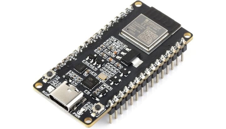
The Waveshare ESP32-H2-DEV-KIT-N4-M is a development board based on the ESP32-H2, available for only $6.65 on Aliexpress, but you’ll also find it on Amazon and Waveshare’s official store. This is a significant price drop compared to last year’s official Espressif ESP32-H2-DevKitM-1 board, which was priced at $10 without including shipping costs and with a similar design. In 2021, Espressif Systems introduced the ESP32-H2 to the world. However, it wasn’t until 2023 that they released their first development board. Since then, there haven’t been many products built around this new module. Some exceptions include the Olimex ESP32-H2-DevKit-LiPo, LILYGO T-Panel, and the ESP Thread Border Router/Zigbee Gateway board, all of which feature the ESP32-H2 chip. Waveshare ESP32-H2-DEV-KIT-N4-M specifications: Wireless module – ESP32-H2-MINI-1 MCU – Espressif Systems ESP32-H2 32-bit RISC-V microcontroller at up to 96 MHz with 320 KB SRAM, 128 KB ROM, 4 KB LP memory, Bluetooth 5.2 LE/Mesh, and 802.15.4 (Zigbee/Thread/Matter) radios. [...]
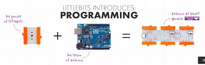
We are excited to announce that littleBits joined the Arduino At Heart Program to easily incorporate programming into littleBits circuits!
littleBits Arduino Module is everything you know and love about Arduino without the breadboarding, soldering or wiring. littleBits takes care of the electronics, while you focus on the code.
The new littleBits Arduino Module allows to:
• Create code using the Arduino programming environment
• Communicate with software (Processing, MaxMSP, Flash etc…)
• Play with 3 inputs and 3 outputs using littleBits bitSnap™ magnetic connector as well as additional I/O for advanced hardware interaction
• Getting started with 10 sketches, including Analog Pong, Tone Libraries and more!
• Access to Arduino AND littleBits community support
Inventing on this platform requires the user to be able to debug through electronics issues as well as software bugs.
For example, instead of having to solder together a complete circuit of power, ground, resistors and LEDs, a user can simply snap a power and an LED module to the Arduino module and dive straight into programming. This will make hardware innovation even more friendly for beginners, and further lower the entry to physical computation.
Take a look at the video and discover what you could do with it!
Printoo’s flexible modules provide the ideal form factor to quickly create first product concepts for smart wearables devices. BITalino (http://www.bitalino.com/) is revolutionizing DIY health tracking by making physiological sensors to measure the body’s biosignals accessible to all. Combine the two and it has never been easier to create revolutionary smart wearable concepts to life.
With Printoo, a number of inputs were already available: accelerometer, temperature sensor, capacitive and light sensors. BITalino’s modules for Electromyography (EMG), Electrodermal Activity (EDA) and Electrocardiogram (ECG) can be easily connected to Printoo through a flexible coupling board. Combine these inputs with flexible LEDs (in strip or matrix form), electrochromic displays, a sound buzzer, as well as Bluetooth Low Energy connectivity, and the possibilities are endless.
BITalino – Create projects with physiological sensors - [Link]
Working with GSM modules and by extension Arduino GSM shields can either be a lot of fun or bring on a migraine. This is usually due to the quality of module, conditions placed on the end user by the network, reception, power supply and more.
Furthermore we have learned after several years that even after following our detailed and tested tutorials, people are having trouble understanding why their GSM shield isn’t behaving. With this in mind we’re very happy to have learned about a free online tool that can be used to test almost every parameter of a GSM module with ease – AT Command Tester. This software is a Java application that runs in a web browser, and communicates with a GSM module via an available serial port.
Initial Setup
It’s simple, just visit http://m2msupport.net/m2msupport/module-tester/ with any web browser that can run Java. You may need to alter the Java security settings down to medium. Windows users can find this in Control Panel> All Control Panel Items > Java – for example:
Once the security settings have been changed, just visit the URL, click ‘accept’ and ‘run’ in the next dialogue box that will appear, for example:
And after a moment, the software will appear:
Once you’re able to run the AT Command Tester software, the next step is to physically connect the hardware. If you’re just using a bare GSM module, a USB-serial adaptor can be used for easy connection to the PC. For Arduino GSM shield users, you can use the Arduino as a bridge between the shield and PC, however if your GSM shield uses pins other than D0/D1 for serial data transmission (such as our SIM900 shield) then you’ll need to upload a small sketch to bridge the software and hardware serial ports, for example:
//Serial Relay – Arduino will patch a serial link between the computer and the GPRS Shield
//at 19200 bps 8-N-1 Computer is connected to Hardware UART
//GPRS Shield is connected to the Software UART

#include <SoftwareSerial.h>

SoftwareSerial mySerial(7,8); // change these paramters depending on your Arduino GSM Shield

void setup()
{
  Serial.begin(19200);
  //Serial.println(“Begin”);
  mySerial.begin(19200);

}

void loop()
{
  if (mySerial.available())
    Serial.write(mySerial.read());
  if (Serial.available())
    mySerial.write(Serial.read());
}
Using the software
Once you have the hardware connected and the Arduino running the required sketch, run the software – then click “Find ports” to select the requried COM: port, set the correct data speed and click “Connect”. After a moment the software will interrogate the GSM module and report its findings in the yellow log area:
As you can see on the left of the image above, there is a plethora of options and functions you can run on the module. By selecting the manufacturer of your GSM module form the list, a more appropriate set of functions for your module is displayed.
When you click a function, the AT command sent to the module and its response is shown in the log window – and thus the magic of this software. You can simply throw any command at the module and await the response, much easier than looking up the commands and fighting with terminal software. You can also send AT commands in batches, experiment with GPRS data, FTP, and the GPS if your module has one.
To give you a quick overview of what is possible, we’ve made this video which captures us running a few commands on a SIM900-based Arduino shield. If possible, view it in 720p.
Conclusion
Kudos to the people from the M2Msupport website for bringing us this great (and free) tool. It works – so we’re happy to recommend it. And if you enjoyed this article, or want to introduce someone else to the interesting world of Arduino – check out my book (now in a third printing!) “Arduino Workshop”.
Have fun and keep checking into tronixstuff.com. Why not follow things on twitter, Google+, subscribe for email updates or RSS using the links on the right-hand column, or join our forum – dedicated to the projects and related items on this website. Sign up – it’s free, helpful to each other – and we can all learn something.
Time for another kit review, and in this instalment we’ve received some LED matrix modules and a matching Arduino-compatible controller board from friedcircuits.us. Behind the name is William Garrido – who some of you may know as “mobile will” from following his blog. Over time William has created a range of small and useful products, which are now available on the tindie online store.
The system comprises of two modules. The first is a small Arduino-compatible board with an ATmega328P microcontroller – the LED matrix master. It’s quite small and is designed to be the start of a chain of matching LED matrix link boards. Each of these holds an 8×8 LED matrix and is controlled by the AS1107 LED driver IC. This is a direct replacement IC for the popular MAX7219, works exactly the same and is a great find instead of using knock-off MAX7219s. You can chain up to 8 matrix modules from the one controller. We received a matrix master and two matrix link boards to examine, which arrived in solid packaging a fun Tindie sticker:
Assembly
All the surface-mount soldering is done in advance, leaving you with some simple through-hole soldering for the LED matrix and the connectors between each module. The PCBs are clearly labelled with the silk screen and have mounting holes for permanent installations:
So after a few minutes of soldering it’s time to get the blinking on:
You may have noticed by now that the master board doesn’t have a USB socket, so you’ll need a 5V FTDI cable or a USBasp programmer to upload your Arduino sketches or AVR .hex file to get things moving.
Controlling a matrix or more
As the system is basically an Arduino-compatible with one or more MAX7219-compatible modules you can find all sorts of example sketches to experiment with. If you haven’t used a MAX7219/AS1107 before there are a couple of starting points including the Arduino library and another random tutorial. Using an example sketch on the Arduino forum by member “danigom“, and after checking the data, clock and load pins it was ready to go. Here’s the sketch for your consideration:
/* Program is currently hard coded to drive 4x MAX7219 chips
   though altering code to drive upto 7 chips is trivial
   Orginal sketch by Arduino forum member "danigom"
   http://forum.arduino.cc/index.php?action=profile;u=188950
*/

//We always have to include the libraries
#include <avr/pgmspace.h>
#include <LedControl.h>

// *CONSTANTS
const int DIN = 12;            //DataIn pin (18)
const int CLK = 11;            //Clock pin (17)
const int LOAD = 10;           //Load pin (16)
const int numDevices = 2;      //Number of MAX7219 LED Driver Chips (1-8)
const long scrollDelay = 70;

prog_uchar font5x7 [] PROGMEM = {      //Numeric Font Matrix (Arranged as 7x font data + 1x kerning data)
    B00000000,	//Space (Char 0x20)
    B00000000,
    B00000000,
    B00000000,
    B00000000,
    B00000000,
    B00000000,
    6,

    B10000000,	//!
    B10000000,
    B10000000,
    B10000000,
    B00000000,
    B00000000,
    B10000000,
    2,

    B10100000,	//"
    B10100000,
    B10100000,
    B00000000,
    B00000000,
    B00000000,
    B00000000,
    4,

    B01010000,	//#
    B01010000,
    B11111000,
    B01010000,
    B11111000,
    B01010000,
    B01010000,
    6,

    B00100000,	//$
    B01111000,
    B10100000,
    B01110000,
    B00101000,
    B11110000,
    B00100000,
    6,

    B11000000,	//%
    B11001000,
    B00010000,
    B00100000,
    B01000000,
    B10011000,
    B00011000,
    6,

    B01100000,	//&
    B10010000,
    B10100000,
    B01000000,
    B10101000,
    B10010000,
    B01101000,
    6,

    B11000000,	//'
    B01000000,
    B10000000,
    B00000000,
    B00000000,
    B00000000,
    B00000000,
    3,

    B00100000,	//(
    B01000000,
    B10000000,
    B10000000,
    B10000000,
    B01000000,
    B00100000,
    4,

    B10000000,	//)
    B01000000,
    B00100000,
    B00100000,
    B00100000,
    B01000000,
    B10000000,
    4,

    B00000000,	//*
    B00100000,
    B10101000,
    B01110000,
    B10101000,
    B00100000,
    B00000000,
    6,

    B00000000,	//+
    B00100000,
    B00100000,
    B11111000,
    B00100000,
    B00100000,
    B00000000,
    6,

    B00000000,	//,
    B00000000,
    B00000000,
    B00000000,
    B11000000,
    B01000000,
    B10000000,
    3,

    B00000000,	//-
    B00000000,
    B11111000,
    B00000000,
    B00000000,
    B00000000,
    B00000000,
    6,

    B00000000,	//.
    B00000000,
    B00000000,
    B00000000,
    B00000000,
    B11000000,
    B11000000,
    3,

    B00000000,	///
    B00001000,
    B00010000,
    B00100000,
    B01000000,
    B10000000,
    B00000000,
    6,

    B01110000,	//0
    B10001000,
    B10011000,
    B10101000,
    B11001000,
    B10001000,
    B01110000,
    6,

    B01000000,	//1
    B11000000,
    B01000000,
    B01000000,
    B01000000,
    B01000000,
    B11100000,
    4,

    B01110000,	//2
    B10001000,
    B00001000,
    B00010000,
    B00100000,
    B01000000,
    B11111000,
    6,

    B11111000,	//3
    B00010000,
    B00100000,
    B00010000,
    B00001000,
    B10001000,
    B01110000,
    6,

    B00010000,	//4
    B00110000,
    B01010000,
    B10010000,
    B11111000,
    B00010000,
    B00010000,
    6,

    B11111000,	//5
    B10000000,
    B11110000,
    B00001000,
    B00001000,
    B10001000,
    B01110000,
    6,

    B00110000,	//6
    B01000000,
    B10000000,
    B11110000,
    B10001000,
    B10001000,
    B01110000,
    6,

    B11111000,	//7
    B10001000,
    B00001000,
    B00010000,
    B00100000,
    B00100000,
    B00100000,
    6,

    B01110000,	//8
    B10001000,
    B10001000,
    B01110000,
    B10001000,
    B10001000,
    B01110000,
    6,

    B01110000,	//9
    B10001000,
    B10001000,
    B01111000,
    B00001000,
    B00010000,
    B01100000,
    6,

    B00000000,	//:
    B11000000,
    B11000000,
    B00000000,
    B11000000,
    B11000000,
    B00000000,
    3,

    B00000000,	//;
    B11000000,
    B11000000,
    B00000000,
    B11000000,
    B01000000,
    B10000000,
    3,

    B00010000,	//<
    B00100000,
    B01000000,
    B10000000,
    B01000000,
    B00100000,
    B00010000,
    5,

    B00000000,	//=
    B00000000,
    B11111000,
    B00000000,
    B11111000,
    B00000000,
    B00000000,
    6,

    B10000000,	//>
    B01000000,
    B00100000,
    B00010000,
    B00100000,
    B01000000,
    B10000000,
    5,

    B01110000,	//?
    B10001000,
    B00001000,
    B00010000,
    B00100000,
    B00000000,
    B00100000,
    6,

    B01110000,	//@
    B10001000,
    B00001000,
    B01101000,
    B10101000,
    B10101000,
    B01110000,
    6,

    B01110000,	//A
    B10001000,
    B10001000,
    B10001000,
    B11111000,
    B10001000,
    B10001000,
    6,

    B11110000,	//B
    B10001000,
    B10001000,
    B11110000,
    B10001000,
    B10001000,
    B11110000,
    6,

    B01110000,	//C
    B10001000,
    B10000000,
    B10000000,
    B10000000,
    B10001000,
    B01110000,
    6,

    B11100000,	//D
    B10010000,
    B10001000,
    B10001000,
    B10001000,
    B10010000,
    B11100000,
    6,

    B11111000,	//E
    B10000000,
    B10000000,
    B11110000,
    B10000000,
    B10000000,
    B11111000,
    6,

    B11111000,	//F
    B10000000,
    B10000000,
    B11110000,
    B10000000,
    B10000000,
    B10000000,
    6,

    B01110000,	//G
    B10001000,
    B10000000,
    B10111000,
    B10001000,
    B10001000,
    B01111000,
    6,

    B10001000,	//H
    B10001000,
    B10001000,
    B11111000,
    B10001000,
    B10001000,
    B10001000,
    6,

    B11100000,	//I
    B01000000,
    B01000000,
    B01000000,
    B01000000,
    B01000000,
    B11100000,
    4,

    B00111000,	//J
    B00010000,
    B00010000,
    B00010000,
    B00010000,
    B10010000,
    B01100000,
    6,

    B10001000,	//K
    B10010000,
    B10100000,
    B11000000,
    B10100000,
    B10010000,
    B10001000,
    6,

    B10000000,	//L
    B10000000,
    B10000000,
    B10000000,
    B10000000,
    B10000000,
    B11111000,
    6,

    B10001000,	//M
    B11011000,
    B10101000,
    B10101000,
    B10001000,
    B10001000,
    B10001000,
    6,

    B10001000,	//N
    B10001000,
    B11001000,
    B10101000,
    B10011000,
    B10001000,
    B10001000,
    6,

    B01110000,	//O
    B10001000,
    B10001000,
    B10001000,
    B10001000,
    B10001000,
    B01110000,
    6,

    B11110000,	//P
    B10001000,
    B10001000,
    B11110000,
    B10000000,
    B10000000,
    B10000000,
    6,

    B01110000,	//Q
    B10001000,
    B10001000,
    B10001000,
    B10101000,
    B10010000,
    B01101000,
    6,

    B11110000,	//R
    B10001000,
    B10001000,
    B11110000,
    B10100000,
    B10010000,
    B10001000,
    6,

    B01111000,	//S
    B10000000,
    B10000000,
    B01110000,
    B00001000,
    B00001000,
    B11110000,
    6,

    B11111000,	//T
    B00100000,
    B00100000,
    B00100000,
    B00100000,
    B00100000,
    B00100000,
    6,

    B10001000,	//U
    B10001000,
    B10001000,
    B10001000,
    B10001000,
    B10001000,
    B01110000,
    6,

    B10001000,	//V
    B10001000,
    B10001000,
    B10001000,
    B10001000,
    B01010000,
    B00100000,
    6,

    B10001000,	//W
    B10001000,
    B10001000,
    B10101000,
    B10101000,
    B10101000,
    B01010000,
    6,

    B10001000,	//X
    B10001000,
    B01010000,
    B00100000,
    B01010000,
    B10001000,
    B10001000,
    6,

    B10001000,	//Y
    B10001000,
    B10001000,
    B01010000,
    B00100000,
    B00100000,
    B00100000,
    6,

    B11111000,	//Z
    B00001000,
    B00010000,
    B00100000,
    B01000000,
    B10000000,
    B11111000,
    6,

    B11100000,	//[
    B10000000,
    B10000000,
    B10000000,
    B10000000,
    B10000000,
    B11100000,
    4,

    B00000000,	//(Backward Slash)
    B10000000,
    B01000000,
    B00100000,
    B00010000,
    B00001000,
    B00000000,
    6,

    B11100000,	//]
    B00100000,
    B00100000,
    B00100000,
    B00100000,
    B00100000,
    B11100000,
    4,

    B00100000,	//^
    B01010000,
    B10001000,
    B00000000,
    B00000000,
    B00000000,
    B00000000,
    6,

    B00000000,	//_
    B00000000,
    B00000000,
    B00000000,
    B00000000,
    B00000000,
    B11111000,
    6,

    B10000000,	//`
    B01000000,
    B00100000,
    B00000000,
    B00000000,
    B00000000,
    B00000000,
    4,

    B00000000,	//a
    B00000000,
    B01110000,
    B00001000,
    B01111000,
    B10001000,
    B01111000,
    6,

    B10000000,	//b
    B10000000,
    B10110000,
    B11001000,
    B10001000,
    B10001000,
    B11110000,
    6,

    B00000000,	//c
    B00000000,
    B01110000,
    B10001000,
    B10000000,
    B10001000,
    B01110000,
    6,

    B00001000,	//d
    B00001000,
    B01101000,
    B10011000,
    B10001000,
    B10001000,
    B01111000,
    6,

    B00000000,	//e
    B00000000,
    B01110000,
    B10001000,
    B11111000,
    B10000000,
    B01110000,
    6,

    B00110000,	//f
    B01001000,
    B01000000,
    B11100000,
    B01000000,
    B01000000,
    B01000000,
    6,

    B00000000,	//g
    B01111000,
    B10001000,
    B10001000,
    B01111000,
    B00001000,
    B01110000,
    6,

    B10000000,	//h
    B10000000,
    B10110000,
    B11001000,
    B10001000,
    B10001000,
    B10001000,
    6,

    B01000000,	//i
    B00000000,
    B11000000,
    B01000000,
    B01000000,
    B01000000,
    B11100000,
    4,

    B00010000,	//j
    B00000000,
    B00110000,
    B00010000,
    B00010000,
    B10010000,
    B01100000,
    5,

    B10000000,	//k
    B10000000,
    B10010000,
    B10100000,
    B11000000,
    B10100000,
    B10010000,
    5,

    B11000000,	//l
    B01000000,
    B01000000,
    B01000000,
    B01000000,
    B01000000,
    B11100000,
    4,

    B00000000,	//m
    B00000000,
    B11010000,
    B10101000,
    B10101000,
    B10001000,
    B10001000,
    6,

    B00000000,	//n
    B00000000,
    B10110000,
    B11001000,
    B10001000,
    B10001000,
    B10001000,
    6,

    B00000000,	//o
    B00000000,
    B01110000,
    B10001000,
    B10001000,
    B10001000,
    B01110000,
    6,

    B00000000,	//p
    B00000000,
    B11110000,
    B10001000,
    B11110000,
    B10000000,
    B10000000,
    6,

    B00000000,	//q
    B00000000,
    B01101000,
    B10011000,
    B01111000,
    B00001000,
    B00001000,
    6,

    B00000000,	//r
    B00000000,
    B10110000,
    B11001000,
    B10000000,
    B10000000,
    B10000000,
    6,

    B00000000,	//s
    B00000000,
    B01110000,
    B10000000,
    B01110000,
    B00001000,
    B11110000,
    6,

    B01000000,	//t
    B01000000,
    B11100000,
    B01000000,
    B01000000,
    B01001000,
    B00110000,
    6,

    B00000000,	//u
    B00000000,
    B10001000,
    B10001000,
    B10001000,
    B10011000,
    B01101000,
    6,

    B00000000,	//v
    B00000000,
    B10001000,
    B10001000,
    B10001000,
    B01010000,
    B00100000,
    6,

    B00000000,	//w
    B00000000,
    B10001000,
    B10101000,
    B10101000,
    B10101000,
    B01010000,
    6,

    B00000000,	//x
    B00000000,
    B10001000,
    B01010000,
    B00100000,
    B01010000,
    B10001000,
    6,

    B00000000,	//y
    B00000000,
    B10001000,
    B10001000,
    B01111000,
    B00001000,
    B01110000,
    6,

    B00000000,	//z
    B00000000,
    B11111000,
    B00010000,
    B00100000,
    B01000000,
    B11111000,
    6,

    B00100000,	//{
    B01000000,
    B01000000,
    B10000000,
    B01000000,
    B01000000,
    B00100000,
    4,

    B10000000,	//|
    B10000000,
    B10000000,
    B10000000,
    B10000000,
    B10000000,
    B10000000,
    2,

    B10000000,	//}
    B01000000,
    B01000000,
    B00100000,
    B01000000,
    B01000000,
    B10000000,
    4,

    B00000000,	//~
    B00000000,
    B00000000,
    B01101000,
    B10010000,
    B00000000,
    B00000000,
    6,

    B01100000,	// (Char 0x7F)
    B10010000,
    B10010000,
    B01100000,
    B00000000,
    B00000000,
    B00000000,
    5
};

prog_uchar scrollText[] PROGMEM ={
    "  THE QUICK BROWN FOX JUMPED OVER THE LAZY DOG 1234567890 the quick brown fox jumped over the lazy dog   \0"};

// * GLOBAL VARIABLES
unsigned long bufferLong [14] = {0};  //Buffer for scrolling text
LedControl lc=LedControl(DIN,CLK,LOAD,numDevices);

void setup(){
    for (int x=0; x<numDevices; x++){
        lc.shutdown(x,false);       //The MAX72XX is in power-saving mode on startup
        lc.setIntensity(x,8);       // Set the brightness to default value
        lc.clearDisplay(x);         // and clear the display
    }
}

void loop(){
    scrollMessage(scrollText);
    scrollFont();
}

void scrollFont() {
    for (int counter=0x20;counter<0x80;counter++){
        loadBufferLong(counter);
        delay(500);
    }
}

// Scroll Message
void scrollMessage(prog_uchar * messageString) {
    int counter = 0;
    int myChar=0;
    do {
        // read back a char
        myChar =  pgm_read_byte_near(messageString + counter);
        if (myChar != 0){
            loadBufferLong(myChar);
        }
        counter++;
    }
    while (myChar != 0);
}
// Load character into scroll buffer
void loadBufferLong(int ascii){
    if (ascii >= 0x20 && ascii <=0x7f){
        for (int a=0;a<7;a++){                      // Loop 7 times for a 5x7 font
            unsigned long c = pgm_read_byte_near(font5x7 + ((ascii - 0x20) * 8) + a);     // Index into character table to get row data
            unsigned long x = bufferLong [a*2];     // Load current scroll buffer
            x = x | c;                              // OR the new character onto end of current
            bufferLong [a*2] = x;                   // Store in buffer
        }
        byte count = pgm_read_byte_near(font5x7 +((ascii - 0x20) * 8) + 7);     // Index into character table for kerning data
        for (byte x=0; x<count;x++){
            rotateBufferLong();
            printBufferLong();
            delay(scrollDelay);
        }
    }
}
// Rotate the buffer
void rotateBufferLong(){
    for (int a=0;a<7;a++){                      // Loop 7 times for a 5x7 font
        unsigned long x = bufferLong [a*2];     // Get low buffer entry
        byte b = bitRead(x,31);                 // Copy high order bit that gets lost in rotation
        x = x<<1;                               // Rotate left one bit
        bufferLong [a*2] = x;                   // Store new low buffer
        x = bufferLong [a*2+1];                 // Get high buffer entry
        x = x<<1;                               // Rotate left one bit
        bitWrite(x,0,b);                        // Store saved bit
        bufferLong [a*2+1] = x;                 // Store new high buffer
    }
}
// Display Buffer on LED matrix
void printBufferLong(){
  for (int a=0;a<7;a++){                    // Loop 7 times for a 5x7 font
    unsigned long x = bufferLong [a*2+1];   // Get high buffer entry
    byte y = x;                             // Mask off first character
    lc.setRow(3,a,y);                       // Send row to relevent MAX7219 chip
    x = bufferLong [a*2];                   // Get low buffer entry
    y = (x>>24);                            // Mask off second character
    lc.setRow(2,a,y);                       // Send row to relevent MAX7219 chip
    y = (x>>16);                            // Mask off third character
    lc.setRow(1,a,y);                       // Send row to relevent MAX7219 chip
    y = (x>>8);                             // Mask off forth character
    lc.setRow(0,a,y);                       // Send row to relevent MAX7219 chip
  }
}
In the following video you can see the sketch in action with two and one matrix modules:
Where to from here?
The matrix modules can find a wide range of uses, from simple fun and scrolling text to various LED matrix games, status displays and more. They also work well with the XOBXOB IoT USB-connected example. The design files are available for perusal on the friedcircuits github page. And don’t forget the matrix master board in itself is a tiny Arduino-compatible – with the full eight ADCs and digital I/O pins available. Thus you can embed this in another project if so desired.
Conclusion
The LED matrix modules are simple to use and work well together. Plus the matrix master board makes for a neat little Arduino-compatible as well. For more information and to order, visit the friedcircuits.us website. Full-sized images are on flickr. And if you made it this far – check out my new book “Arduino Workshop” from No Starch Press.
In the meanwhile have fun and keep checking into tronixstuff.com. Why not follow things on twitter, Google+, subscribe for email updates or RSS using the links on the right-hand column? And join our friendly Google Group – dedicated to the projects and related items on this website. Sign up – it’s free, helpful to each other – and we can all learn something.
[Note - kits reviewed were a promotional consideration from friedcircuits]
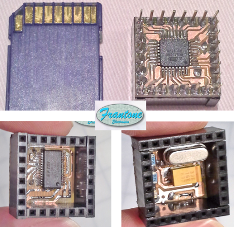
[Fran's] been working on her own version of the Arduino. She calls it CuteUino for obvious reasons. The size of the thing is pretty remarkable, fitting within the outline of an SD card. But that doesn’t mean you won’t get the power that you’re used to with the device. She’s broken it up into several modules so you can choose only the components that you need for the project.
The main board is shown on the right, both top and bottom. It sports the ATmega328p (it’s hard to believe we could make out the label on the chip package in the clip after the break) in a TQFP-32 package soldered to the underside of what she calls the Brain Module. You can also see the extra long pins which stick through from the female pin headers mounted on the top side of the board. Inside of these pin headers you’ll find the clock crystal, status LEDs, and a capacitor. The other module is an FTDI board used to connect the AVR chip to a USB port.
You’ll definitely want to check out her prototyping post for this project. She uses a very interesting technique of combining two single-sided boards to make a 3-layer PCB. The side that was not copper clad is fitted with copper foil by hand to act as a ground plane for the vias. Neat!
[Will] was toying with the idea of creating a scrolling LED marquee to display messages as his wedding in May. But you’ve got to crawl before you can walk so he decided to see what he could do with the MAX7219 LED driver chips. They do come in a DIP package, but the 24-pin 0.1″ pitch chip will end up being larger than the 8×8 LED modules he wanted to use. So he opted to go with a surface mount part and spun a PCB which makes the LEDs modular.
These drivers are great when you’re dealing with a lot of LEDs (like the motorcycle helmet of many blinking colors). Since they use SPI for communications it’s possible to chain the chips with a minimum of connections. [Will] designed his board to have a male header on one side and a female socket on the other. Not only does it make aligning and connecting each block simple, but it allows you to change your mind at any time about which microcontroller to use to command them. For his first set of tests he plugged the male header into a breadboard and drove it with an Arduino. We hope to hear back from him with an update when gets the final device assembled in time for the big day.
Learn how to use very inexpensive KTM-S1201 LCD modules in this edition of our Arduino tutorials. This is chapter forty-nine of a series originally titled “Getting Started/Moving Forward with Arduino!” by John Boxall – A tutorial on the Arduino universe. The first chapter is here, the complete series is detailed here.
Introduction
After looking for some displays to use with another (!) clock, I came across some 12-digit numeric LCD displays. They aren’t anything flash, and don’t have a back light – however they were one dollar each. How could you say no to that? So I ordered a dozen to try out. The purpose of this tutorial is to show you how they are used with an Arduino in the simplest manner possible.
Moving forward – the modules look like OEM modules for desktop office phones from the 1990s:
With a quick search on the Internet you will find a few sellers offering them for a dollar each. The modules (data sheet) use the NEC PD7225 controller IC (data sheet):
They aren’t difficult to use, so I’ll run through set up and operation with a few examples.
Hardware setup
First you’ll need to solder some sort of connection to the module – such as 2×5 header pins. This makes it easy to wire it up to a breadboard or a ribbon cable:
The rest of the circuitry is straight-forward. There are ten pins in two rows of five, and with the display horizontal and the pins on the right, they are numbered as such:
Now make the following connections:
LCD pin 1 to 5V
LCD pin 2 to GND
LCD pin 3 to Arduino D4
LCD pin 4 to Arduino D5
LCD pin 5 to Arduino D6
LCD pin 6 to Arduino D7
LCD pin 7 – not connected
LCD pin 8 – Arduino D8
LCD pin 9 to the centre pin of a 10k trimpot – whose other legs connect to 5V and GND. This is used to adjust the contrast of the LCD.
The Arduino digital pins that are used can be changed – they are defined in the header file (see further on). If you were curious as to how low-current these modules are:
That’s 0.689 mA- not bad at all. Great for battery-powered operations. Now that you’ve got the module wired up, let’s get going with some demonstration sketches.
Software setup
The sketches used in this tutorial are based on work by Jeff Albertson and Robert Mech, so kudos to them – however we’ve simplified them a little to make use easier. We’ll just cover the functions required to display data on the LCD. However feel free to review the sketches and files along with the controller chip datasheet as you’ll get an idea of how the controller is driven by the Arduino.
When using the LCD module you’ll need a header file in the same folder as your sketch. You can download the header file from here. Then every time you open a sketch that uses the header file, it should appear in a tab next to the main sketch, for example:
There’s also a group of functions and lines required in your sketch. We’ll run through those now – so download the first example sketch, add the header file and upload it. Your results should be the same as the video below:
So how did that work? Take a look at the sketch you uploaded. You need all the functions between the two lines of “////////////////////////” and also the five lines in void setup(). Then you can display a string of text or numbers using
ktmWriteString();
which was used in void loop(). You can use the digits 0~9, the alphabet (well, what you can do with 7-segments), the degrees symbol (use an asterix – “*”) and a dash (use - “-”). So if your sketch can put together the data to display in a string, then that’s taken care of.
If you want to clear the screen, use:
ktmCommand(_ClearDsp);
Next – to individually place digits on the screen, use the function:
tmPrnNumb(n,p,d,l);
Where n is the number to be displayed (zero or a positive integer), p is the position on the LCD for the number’s (the positions from left to right are 11 to 0…), d is the number of digits to the right of the decimal point (leave as zero if you don’t want a decimal point), and l is the number of digits being displayed for n. When you display digits using this function you can use more than one function to compose the number to be displayed – as this function doesn’t clear the screen.
To help get your head around it, the following example sketch (download) has a variety of examples in void loop(). You can watch this example in the following video:
Conclusion
So there you have it – an incredibly inexpensive and possibly useful LCD module. Thank you to Jeff Albertson and Robert Mech for their help and original code.
In the meanwhile have fun and keep checking into tronixstuff.com. Why not follow things on twitter, Google+, subscribe for email updates or RSS using the links on the right-hand column? And join our friendly Google Group – dedicated to the projects and related items on this website. Sign up – it’s free, helpful to each other – and we can all learn something.
Learn how to use very inexpensive KTM-S1201 LCD modules in this edition of our Arduino tutorials. This is chapter forty-nine of a series originally titled “Getting Started/Moving Forward with Arduino!” by John Boxall – A tutorial on the Arduino universe. The first chapter is here, the complete series is detailed here.
Introduction
After looking for some displays to use with another (!) clock, I came across some 12-digit numeric LCD displays. They aren’t anything flash, and don’t have a back light – however they were one dollar each. How could you say no to that? So I ordered a dozen to try out. The purpose of this tutorial is to show you how they are used with an Arduino in the simplest manner possible.
Moving forward – the modules look like OEM modules for desktop office phones from the 1990s:
With a quick search on the Internet you will find a few sellers offering them for a dollar each. The modules (data sheet) use the NEC PD7225 controller IC (data sheet):
They aren’t difficult to use, so I’ll run through set up and operation with a few examples.
Hardware setup
First you’ll need to solder some sort of connection to the module – such as 2×5 header pins. This makes it easy to wire it up to a breadboard or a ribbon cable:
The rest of the circuitry is straight-forward. There are ten pins in two rows of five, and with the display horizontal and the pins on the right, they are numbered as such:
Now make the following connections:
LCD pin 1 to 5V
LCD pin 2 to GND
LCD pin 3 to Arduino D4
LCD pin 4 to Arduino D5
LCD pin 5 to Arduino D6
LCD pin 6 to Arduino D7
LCD pin 7 – not connected
LCD pin 8 – Arduino D8
LCD pin 9 to the centre pin of a 10k trimpot – whose other legs connect to 5V and GND. This is used to adjust the contrast of the LCD.
The Arduino digital pins that are used can be changed – they are defined in the header file (see further on). If you were curious as to how low-current these modules are:
That’s 0.689 mA- not bad at all. Great for battery-powered operations. Now that you’ve got the module wired up, let’s get going with some demonstration sketches.
Software setup
The sketches used in this tutorial are based on work by Jeff Albertson and Robert Mech, so kudos to them – however we’ve simplified them a little to make use easier. We’ll just cover the functions required to display data on the LCD. However feel free to review the sketches and files along with the controller chip datasheet as you’ll get an idea of how the controller is driven by the Arduino.
When using the LCD module you’ll need a header file in the same folder as your sketch. You can download the header file from here. Then every time you open a sketch that uses the header file, it should appear in a tab next to the main sketch, for example (click to enlarge):
There’s also a group of functions and lines required in your sketch. We’ll run through those now – so download the first example sketch, add the header file and upload it. Your results should be the same as the video below:
So how did that work? Take a look at the sketch you uploaded. You need all the functions between the two lines of “////////////////////////” and also the five lines in void setup(). Then you can display a string of text or numbers using
ktmWriteString();
which was used in void loop(). You can use the digits 0~9, the alphabet (well, what you can do with 7-segments), the degrees symbol (use an asterix – “*”) and a dash (use - “-”). So if your sketch can put together the data to display in a string, then that’s taken care of.
If you want to clear the screen, use:
ktmCommand(_ClearDsp);
Next – to individually place digits on the screen, use the function:
ktmPrnNumb(n,p,d,l);
Where n is the number to be displayed (zero or a positive integer), p is the position on the LCD for the number’s (the positions from left to right are 11 to 0…), d is the number of digits to the right of the decimal point (leave as zero if you don’t want a decimal point), and l is the number of digits being displayed for n. When you display digits using this function you can use more than one function to compose the number to be displayed – as this function doesn’t clear the screen.
To help get your head around it, the following example sketch (download) has a variety of examples in void loop(). You can watch this example in the following video:
Conclusion
So there you have it – an incredibly inexpensive and possibly useful LCD module. Thank you to Jeff Albertson and Robert Mech for their help and original code.
In the meanwhile have fun and keep checking into tronixstuff.com. Why not follow things on twitter, Google+, subscribe for email updates or RSS using the links on the right-hand column? And join our friendly Google Group – dedicated to the projects and related items on this website. Sign up – it’s free, helpful to each other – and we can all learn something.
Finally another kit review! Thanks to akafugu in Japan (the people who brought us the Akafuino-X) we have a new clock kit to assemble – the Simpleclock. But first, what is it?
A clock – yes. You can never have too many clocks. Also, a digital thermometer and an alarm clock. It is based on the Atmel ATmega328 and Arduino IDE, with open-source firmware. The real-time clock uses the DS1307 circuit with battery backup that we know and love. This means you can completely modify the clock or concoct a completely different use for your Simpleclock. Countdown timer? There’s an idea…
Furthemore, the display module is their individual I2C-interface TWI Display. Therefore you have a clock as well as some Arduino-based hardware to experiment with later on. However, let’s assemble it first.
Assembly
Putting it all together was quite straight-forward. You can follow the detailed instructions at the akafugu site. All the parts required to make a functional clock as advertised are included with the kit:
Here are the brains of the operation – the pre-programmed microcontroller and the DS1307 real-time clock IC:
You do receive an IC socket for the MCU, but not for the RTC – however this shouldn’t be an issue – just double-check your soldering and have some confidence. The PCBs are nicely laid out with solder-masking and a clear silk-screen:
The PCB on the left in the images above is for the display module – it runs an ATtiny microcontroller than can be worked with separately. Moving forward, you start with the lowest-profile components including the resistors and capacitors:
Take note of the vice – these are great, and light years ahead of the “helping hands” things you see around the traps. This was a Stanley model from element14. The resistors sit in nicely:
The next step is to put a blob of solder on the solder pad which will be beneath the backup battery holder – this forces contact between the negative side of the coin cell battery and the PCB:
Everything else went smoothly – I did have a small worry about the pin spacing for the USB power socket, however a clean tip and a steady hand solved that problem:
The rest of the clock board is much easier – just follow the instructions, take your time and relax. Soon enough you’ll be finished:
However I did have one “oops” moment – I left the PTC in too tall, so it needed to be bent over a little to give way for the display module when inserted:
The next task is to solder the four digit display to the display PCB – nothing new here:
Which leaves you with the standalone display module:
Using the Simpleclock
The firmware for clock use as described in the product page is already loaded in the MCU, so you can use it without needing and programming time or effort. It is powered via a mini-USB cable which you will need to acquire yourself. Frankly the design should have a DC socket and regulator – perhaps for the second revision With second thought, it’s better running from USB. When I turn on the computer in the morning the Simpleclock beeps and ‘wakes up’. The menu system is simple and setting the time and alarm is deceptively so. Some thought has been put into the user interface so once assembled, you could always give the clock away as a gift without fear of being asked for help. However mine is staying on top of the monitor for the office PC:
And here it is in action on the bench:
If you get the urge to modify and update the code, it is easily done. As the Simpleclock kit is open source, all the data required is available from Akafugu’s github page. Please read the notes and other documentation before updating your clock. The easiest way to physically upload the new code will be with a 5V FTDI to USB adaptor or cable.
Conclusion
The Simpleclock was easy to assemble and works very well. It would make a fun kit for those learning to solder, as they have something that once completed is a reminder of their success and useful in daily life. Apart from using USB for power instead of a DC socket – it’s a great kit and I would recommend it to anyone interested in clocks, enjoys kit assembly, or as a gift to a young one to introduce them to electronics and microcontrollers.
Note – the Simpleclock kit was a promotional consideration from akafugu.jp, however the opinions stated are purely my own.
In the meanwhile have fun and keep checking into tronixstuff.com. Why not follow things on twitter, Google+, subscribe for email updates or RSS using the links on the right-hand column? And join our friendly Google Group – dedicated to the projects and related items on this website. Sign up – it’s free, helpful to each other – and we can all learn something.
Planet Arduino is, or at the moment is wishing to become, an aggregation of public weblogs from around the world written by people who develop, play, think on Arduino platform and his son. The opinions expressed in those weblogs and hence this aggregation are those of the original authors. Entries on this page are owned by their authors. We do not edit, endorse or vouch for the contents of individual posts. For more information about Arduino please visit www.arduino.cc
You are currently browsing the archives for the module category.