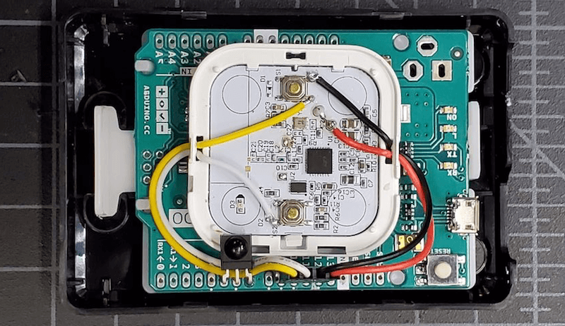
Hacker “replayreb” recently obtained some IKEA FYRTUR motorized blackout shades, but wasn’t satisfied with the stock remote control that comes with them. Instead he wanted to be able to open and close the blinds with the same remote that he uses for AV equipment.
Rather than attempting to go through a home automation gateway setup, he simply opened up the remote and wired an Arduino Leonardo to use its GPIO pins as a low-voltage relay. An IR receiver was added to the Arduino, allowing it to take these signals and translate them into simulated button presses as needed.
We’ve been told that standing at a desk is good for you, but unless you’re some kind of highly advanced automaton you’re going to have to sit down eventually no matter what all those lifestyle magazines say. That’s where desks like the IKEA SKARSTA come in; they use a crank on the front to raise and lower the desk to whatever height your rapidly aging corporeal form is still capable of maintaining. All the health benefits of a standing desk, without that stinging sense of defeat when you later discover you hate it.
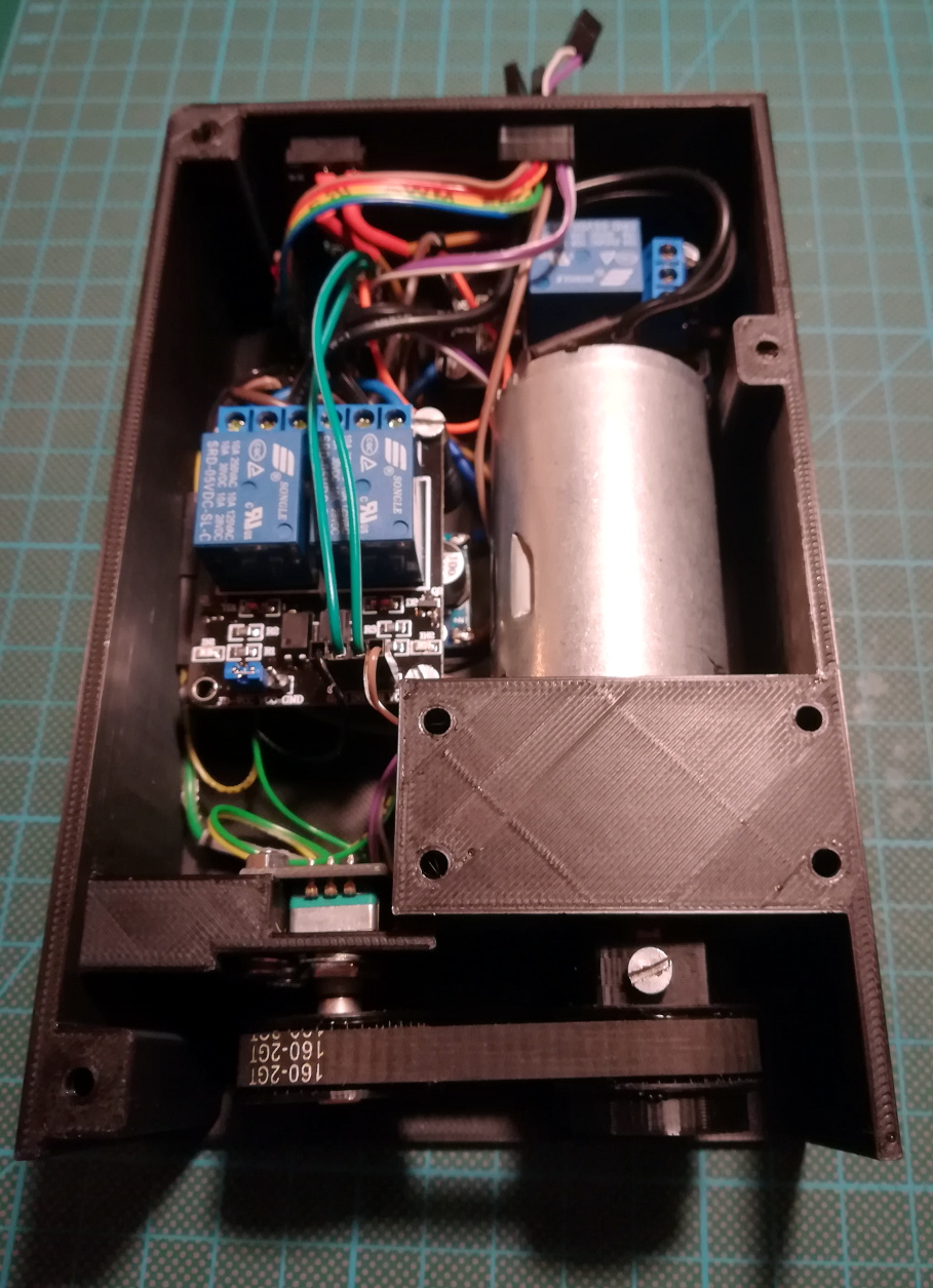
But who wants to turn a crank with their hand in 2019? Certainly not [iLLiac4], who’s spent the last few months working in conjunction with [Martin Mihálek] to add some very impressive features to IKEA’s adjustable table. Replacing the hand crank with a motorized system which can do the raising and lifting was only part of it, the project also includes a slick control panel with a digital display that shows the current table height and even allows the user to set and recall specific positions. The project is still in active development and has a few kinks to work out, but it looks exceptionally promising if you’re looking to get a very capable adjustable desk without breaking the bank.
The heart of the project is a 3D printable device which uses a low-RPM DC gear motor to turn the hex shaft where the crank would normally go. A rotary encoder is linked to the shaft of the motor by way of printed GT2 pulleys and a short length of belt, which gives the system positional information and avoids the complexity of adding limit switches to the table itself.
For controlling the motor the user is given the option between using relays or an H-Bridge PWM driver board, but in either event an Arduino Nano will be running the show. In addition to controlling the motor and reading the output of the rotary encoder, the Arduino also handles the front panel controls. This consists of a TM1637 four digit LED display originally intended for clocks, as well as six momentary contact tactile switches complete with 3D printed caps. The front panel’s simple user interface not only allows for setting and recalling three preset desk heights, but can even be used to perform the calibration routine without having to go in and hack the source code to change minimum and maximum positions.
When the average person looks at a bed, they think about sleeping. Because that’s what beds are for. You cover them with soft, warm cloths and fluffy pillows and you sleep on them. [Peter] is not your average person. He’s a maker. And when he looks at a bed, he thinks about giving it the ability to track his weight.
The IKEA bed has four Chinese-made TS-606 load cells under each foot with custom aluminum enclosures. Each one goes to an HX711 analog-to-digital converter, which offers a 24 bit resolution. These feed an Arduino Nano which in turns connects to a Raspberry Pi via USB to UART bridge. Connecting to the Pi allows [Peter] to get the data onto his home network, where he plots the data to gnuplot.
This smart bed doesn’t just track [Peter’s] weight. It can also track the weight of other people in the house, including his pets. Be sure to check his GitHub for full source code.
There are many ways of remotely-controlling your Arduino or compatible hardware over the Internet. Some are more complex than others, which can be a good thing or a bad thing depending on your level of expertise. Lately we’ve become more interested in this topic and have come across Blynk, which appeared to be a simple solution – and thus the topic of our review.
What is Blynk?
From their website: “Blynk is a Platform with iOS and Android apps to control Arduino, Raspberry Pi and the likes over the Internet. It’s a digital dashboard where you can build a graphic interface for your project by simply dragging and dropping widgets.
It’s really simple to set everything up and you’ll start tinkering in less than 5 mins. Blynk is not tied to some specific board or shield. Instead, it’s supporting hardware of your choice. Whether your Arduino or Raspberry Pi is linked to the Internet over Wi-Fi, Ethernet or this new ESP8266 chip, Blynk will get you online and ready for the Internet Of Your Things.” Here is the original launch video:
Blynk started off as an idea, and raised initial funding through Kickstarter – which was successful and the system has now launched. Blynk comprises of an app on your smartphone (Android or iOS) inside which you can add widgets (controls) to send commands back to your development board (Arduino etc.).
For example, you can add a switch to turn a digital output on or off. Furthermore, data from sensors connected to the development board can be send back to the smartphone. The data passes through the Blynk Cloud server, or you can download and run your own server on your own hardware and infrastructure.
How much does it cost?
Right now (September 2015) the Blynk system is free. We downloaded the app and experimented without charge. We believe that over time there will be payment required for various functions, however you can try it out now to see if Blynk suits your needs then run with it later or experiment with other platforms.
Getting Started
Well enough talk, let’s try Blynk out. Our hardware is an Android smartphone (the awesome new Oppo R7+) for control, and a Freetronics EtherTen connected to our office modem/router:
You can also use other Arduino+Ethernet combinations, such as an Arduino Uno with an Ethernet shield. First you need to download the app for your phone – click here for the links. Then from the same page, download the Arduino library – and install it like you would any other Arduino library.
For our first example, we’ll use an LED connected to digital pin 7 (via a 560 ohm resistor) shown above. Now it’s time to set up the Blynk app. When you run the app for the first time, you need to sign in – so enter an email address and password:
Then click the “+” at the top-right of the display to create a new project, and you should see the following screen:
You can name your project, select the target hardware (Arduino Uno) – then click “E-mail” to send that auth token to yourself – you will need it in a moment. Then click “Create” to enter the main app design screen. Next, press “+” again to get the “Widget Box” menu as shown below, then press “Button”:
This will place a simple button on your screen:
Press the button to open its’ settings menu:
From this screen you can name your button, and also determine whether it will be “momentary” (i.e., only on when you press the button) – or operate as a switch (push on… push off…). Furthermore you need to select which physical Arduino pin the button will control – so press “PIN”, which brings up the scrolling menu as shown below:
We set ours to D7 then pressed “Continue”. Now the app is complete. Now head back to your computer, open the Arduino IDE, and load the “Arduino_Ethernet” sketch included with the library:
Then scroll down to line 30 and enter the auth key that was sent to you via email:
Save then upload the sketch to your Arduino. Now head back to your smartphone, and click the “Play” (looks like a triangle pointing right) button. After a moment the app will connect to the Blynk server… the Arduino will also be connected to the server – and you can press the button on the screen to control the LED.
And that’s it – remote control really is that easy. We’ve run through the process in the following short video:
Data can also travel in the other direction – from your Arduino over the Internet to your smartphone. At the time of writing this (September 2015) you can monitor the status of analogue and digital pins, and widgets can be added in the app to do just that. They can display the value returned from each ADC, which falls between zero and 1023 – and display the values in various forms – for example:
The bandwidth required for this is just under 2 K/s, as you can see from the top of the image above. You can see this in action through the video below:
Conclusion
We have only scratched the surface of what is possible with Blynk – which is an impressive, approachable and usable “Internet of Things” platform. Considering that you can get an inexpensive Android smartphone or tablet for under AU$50, the overall cost of using Blynk is excellent and well worth consideration, even just to test out the “Internet of Things” buzz yourself. So to get started head over to the Blynk site.
A few weeks ago I found a DIODER LED strip set from a long-ago trek to IKEA, and considered that something could be done with it. So in this article you can see how easy it is to control the LEDs using an Arduino or compatible board with ease… opening it up to all sorts of possibilities.
This is not the most original project – however things have been pretty quiet around here, so I thought it was time to share something new with you. Furthermore the DIODER control PCB has changed, so this will be relevant to new purchases. Nevertheless, let’s get on with it.
So what is DIODER anyhow?
As you can see in the image below, the DIODER pack includes four RGB LED units each with nine RGB LEDs per unit. A controller box allows power and colour choice, a distribution box connects between the controller box and the LED strips, and the whole thing is powered by a 12V DC plugpack:
The following is a quick video showing the DIODER in action as devised by IKEA:
Thankfully the plugpack keeps us away from mains voltages, and includes a long detachable cable which connects to the LED strip distribution box. The first thought was to investigate the controller, and you can open it with a standard screwdriver. Carefully pry away the long-side, as two clips on each side hold it together…
… which reveals the PCB. Nothing too exciting here – you can see the potentiometer used for changing the lighting effects, power and range buttons and so on:
Our DIODER has the updated PCB with the Chinese market microcontroller. If you have an older DIODER with a Microchip PIC – you can reprogram it yourself.
The following three MOSFETs are used to control the current to each of the red, green and blue LED circuits. These will be the key to controlling the DIODER’s strips – but are way too small for me to solder to. The original plan was to have an Arduino’s PWM outputs tap into the MOSFET’s gates – but instead I will use external MOSFETs.
So what’s a MOSFET?
In the past you may have used a transistor to switch higher current from an Arduino, however a MOSFET is a better solution for this function. The can control large voltages and high currents without any effort. We will use N-channel MOSFETs, which have three pins – Source, Drain and Gate. When the Gate is HIGH, current will flow into the Drain and out of the Source:
A simplistic explanation is that it can be used like a button – and when wiring your own N-MOSFET a 10k resistor should be used between Gate and Drain to keep the Gate low when the Arduino output is set to LOW (just like de-bouncing a button). To learn more about MOSFETS – get yourself a copy of “The Art of Electronics“. It is worth every cent.
However being somewhat time poor (lazy?), I have instead used a Freetronics NDrive Shield for Arduino – which contains six N-MOSFETs all on one convenient shield – with each MOSFET’s Gate pin connected to an Arduino PWM output.
So let’s head back to the LED strips for a moment, in order to determine how the LEDs are wired in the strip. Thanks to the manufacturer – the PCB has the markings as shown below:
They’re 12V LEDs in a common-anode configuration. How much current do they draw? Depends on how many strips you have connected together…
For the curious I measured each colour at each length, with the results in the following table:
So all four strips turned on, with all colours on – the strips will draw around 165 mA of current at 12V. Those blue LEDs are certainly thirsty.
Moving on, the next step is to connect the strips to the MOSFET shield. This is easy thanks to the cable included in the DIODER pack, just chop the white connector off as shown below:
By connecting an LED strip to the other end of the cable you can then determine which wire is common, and which are the cathodes for red, green and blue.
The plugpack included with the DIODER pack can be used to power the entire project, so you will need cut the DC plug (the plug that connects into the DIODER’s distribution box) off the lead, and use a multimeter to determine which wire is negative, and which is positive.
Connect the negative wire to the GND terminal on the shield, and the positive wire to the Vin terminal. Then…
the red LED wire to the D3 terminal,
the green LED wire to the D9 terminal,
and the blue LED wire to the D10 terminal.
Finally, connect the 12V LED wire (anode) into the Vin terminal. Now double-check your wiring. Then check it again.
Testing
Now to run a test sketch to show the LED strip can easily be controlled. We’ll turn each colour on and off using PWM (Pulse-Width Modulation) – a neat way to control the brightness of each colour. The following sketch will pulse each colour in turn, and there’s also a blink function you can use.
// Controlling IKEA DIODER LED strips with Arduino and Freetronics NDRIVE N-MOSFET shield
// CC by-sa-nc John Boxall 2015 - tronixstuff.com
// Components from tronixlabs.com

#define red 3
#define green 9
#define blue 10
#define delaya 2

void setup()
{
  pinMode(red, OUTPUT);
  pinMode(green, OUTPUT);
  pinMode(blue, OUTPUT);
}

void blinkRGB()
{
  digitalWrite(red, HIGH);
  delay(1000);
  digitalWrite(red, LOW);
  digitalWrite(green, HIGH);
  delay(1000);
  digitalWrite(green, LOW);
  digitalWrite(blue, HIGH);
  delay(1000);
  digitalWrite(blue, LOW);
}

void pulseRed()
{
  for (int i=0; i<256; i++)
  {
    analogWrite(red,i);
    delay(delaya);
  }
  for (int i=255; i>=0; --i)
  {
    analogWrite(red,i);
    delay(delaya);
  }
}

void pulseGreen()
{
  for (int i=0; i<256; i++)
  {
    analogWrite(green,i);
    delay(delaya);
  }
  for (int i=255; i>=0; --i)
  {
    analogWrite(green,i);
    delay(delaya);
  }
}

void pulseBlue()
{
  for (int i=0; i<256; i++)
  {
    analogWrite(blue,i);
    delay(delaya);
  }
  for (int i=255; i>=0; --i)
  {
    analogWrite(blue,i);
    delay(delaya);
  }
}

void loop()
{
  pulseRed();
  pulseGreen();
  pulseBlue();
}
As always, there’s a better way of doing things and one example of LED control is the awesome FASTLED library by Daniel Garcia and others. Go and download it now – https://github.com/FastLED/FastLED. Apart from our simple LEDS, the FASTLED library is also great with WS2812B/Adafruit NeoPixels and others.
One excellent demonstration included with the library is the AnalogOutput sketch, which I have supplied below to work with our example hardware:
#include <FastLED.h>

// Example showing how to use FastLED color functions
// even when you're NOT using a "pixel-addressible" smart LED strip.
//
// This example is designed to control an "analog" RGB LED strip
// (or a single RGB LED) being driven by Arduino PWM output pins.
// So this code never calls FastLED.addLEDs() or FastLED.show().
//
// This example illustrates one way you can use just the portions
// of FastLED that you need.  In this case, this code uses just the
// fast HSV color conversion code.
//
// In this example, the RGB values are output on three separate
// 'analog' PWM pins, one for red, one for green, and one for blue.

#define REDPIN   3
#define GREENPIN 9
#define BLUEPIN  10

// showAnalogRGB: this is like FastLED.show(), but outputs on
// analog PWM output pins instead of sending data to an intelligent,
// pixel-addressable LED strip.
//
// This function takes the incoming RGB values and outputs the values
// on three analog PWM output pins to the r, g, and b values respectively.
void showAnalogRGB( const CRGB& rgb)
{
  analogWrite(REDPIN,   rgb.r );
  analogWrite(GREENPIN, rgb.g );
  analogWrite(BLUEPIN,  rgb.b );
}


// colorBars: flashes Red, then Green, then Blue, then Black.
// Helpful for diagnosing if you've mis-wired which is which.
void colorBars()
{
  showAnalogRGB( CRGB::Red );   delay(500);
  showAnalogRGB( CRGB::Green ); delay(500);
  showAnalogRGB( CRGB::Blue );  delay(500);
  showAnalogRGB( CRGB::Black ); delay(500);
}

void loop()
{
  static uint8_t hue;
  hue = hue + 1;
  // Use FastLED automatic HSV->RGB conversion
  showAnalogRGB( CHSV( hue, 255, 255) );

  delay(20);
}


void setup() {
  pinMode(REDPIN,   OUTPUT);
  pinMode(GREENPIN, OUTPUT);
  pinMode(BLUEPIN,  OUTPUT);

  // Flash the "hello" color sequence: R, G, B, black.
  colorBars();
}
You can see this in action through the following video:
So if you have some IKEA LED strips, or anything else that requires more current than an Arduino’s output pin can offer – you can use MOSFETs to take over the current control and have fun. And finally a plug for my own store – tronixlabs.com – offering a growing range and Australia’s best value for supported hobbyist electronics from adafruit, DFRobot, Freetronics, Seeed Studio and much much more.
As always, have fun and keep checking into tronixstuff.com. Why not follow things on twitter, Google+, subscribe for email updates or RSS using the links on the right-hand column, or join our forum – dedicated to the projects and related items on this website.
[Limpkin], aka Hackaday alum [Matheiu Stephan], is at it again, converting an IKEA lamp into a visual wake-up light. He wants to build an alarm that can be remotely triggered, He’s basing this project around a combination of an ESP8266 that handles the communication and timing, and a pile of 10-watt RGB LEDs. However, he is having a problem: every time he initializes the PWM (pulse width modulation) signalling that will control the level of the LEDs, his ESP8266 dev board reboots. So, he’s offering an interesting bounty for the person who finds the issue: figure it out and he will send you the lamp. Well, the PCB and components, anyway: you’ll have to add your own IKEA lamp. It’s an interesting approach to debugging a hardware problem, so feel free to take a look. The full hardware and software details are on his GitHub repository.
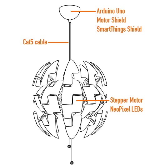
Ikea hacks are well widespread in the maker movement and David Bliss, founder at Nurun, did a great job transforming the Death Star inspired PS 2014 Pendant Lamp into something more dynamic.
The lamp was pimped up with an Arduino Uno and Arduino Motor Shield, NeoPixel LEDs and other components you can see in the illustration.
The detailed description of the project is on his blog , the code on github and the final result in the following video:
[Dzl] and his rather serious looking son are metal detector enthusiasts. But when they couldn’t find their store-bought metal detector earlier this summer they just went ahead and built their own. [Dzl] starts his write up with an explanation of how most oscillator based metal detectors work. This one differs by using an Arduino to read from the metal detecting coil.
The circuit starts with an oscillator that produces a signal of about 160 kHz which is constantly measured by the Arduino. When metal enters the coil it alters the frequency, which is immediately picked up the Arduino. Instead of that characteristic rising tone this rig uses a Piezo buzzer, issuing the type of clicks you’d normally associate with a Geiger counter.
The last part of the build was to find the best coil orientation. They settled on thirty turns around a metal bucket. An old Ikea lamp is the perfect form factor to host their hardware which seems to work like a charm.
Planet Arduino is, or at the moment is wishing to become, an aggregation of public weblogs from around the world written by people who develop, play, think on Arduino platform and his son. The opinions expressed in those weblogs and hence this aggregation are those of the original authors. Entries on this page are owned by their authors. We do not edit, endorse or vouch for the contents of individual posts. For more information about Arduino please visit www.arduino.cc
You are currently browsing the archives for the ikea category.