Posts | Comments

Planet Arduino

Archive for the ‘tool hacks’ Category

A powerful robot awaiting for a verbal command to crush its foes might sound like something from a science fiction film, but now it’s a permanent fixture of the [Making Stuff] garage. Thankfully this robot’s sworn enemy are aluminum cans, and the person controlling it with their voice isn’t a maniacal scientist, just a guy who’s serious about recycling. Well, we hope so anyway.

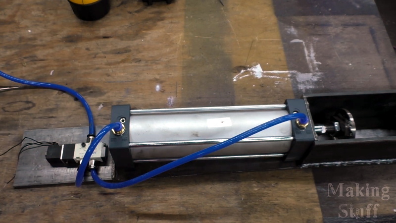
The star of the show is a heavy duty wall-mounted can crusher that [Making Stuff] built from some scrap steel and a pneumatic cylinder hooked up to the garage’s compressed air system. A solenoid operated valve allows an Arduino with attached ESP-01 to extend the cylinder whenever the appropriate command comes over the network. In this case, the goal was to tie the crusher into Google Assistant so a can would get smallified whenever one of Google’s listening devices heard the trigger phrase.

Note the ejector air line.

Obviously, those who’d rather keep Big Data out of their recycling bin don’t have to go down the same path. But that being said, having to give a specific voice command to activate the machine does provide a certain level of operational safety. At least compared to trusting some eBay sensor to tell the difference between an aluminum can and a fleshy appendage.

After crushing a few cans with his new toy, [Making Stuff] noticed a fairly troubling flaw in the design. Each time a can was crushed he had to reach into the maw of the machine to push its little flattened carcass out of the way. In other words, he was one bad line of code away from having one good hand.

The solution ended up being a new hose that runs from the exhaust port of the valve to the crushing chamber: once the cylinder retracts, the air exiting the valve pushes the crushed can out the rear of the machine and into a waiting pail underneath. Very slick.

Even if you’re not interested in the voice control aspect, this is a great design to base your own can crusher on. While it’s always a treat when a fully automatic crusher comes our way, we’ll admit the challenges of getting one to work reliably probably aren’t worth the hassle.


In theory, it’s fun to have a lot of toys tools around, but the sad reality is that it’s only as fun as the organization level applied. Take it from someone who finds organization itself thrilling: it really doesn’t matter how many bits and bobs you have, as long as there’s a place for everything and you put away your toys at the end of the day.

[Cranktown City] is always leaving drill bits lying around instead of putting them back in their bit set boxes. Since he responds well to yelling, he decided to build an intelligent drill bit storage system that berates him if he takes one out and doesn’t put it back within ten minutes.

But [Cranktown City] did much more than that. The system is housed in a really nice DIY stand that supports his new milling and drilling machine and has space to hold a certain type of ubiquitous red tool box beneath the drill bits drawer.

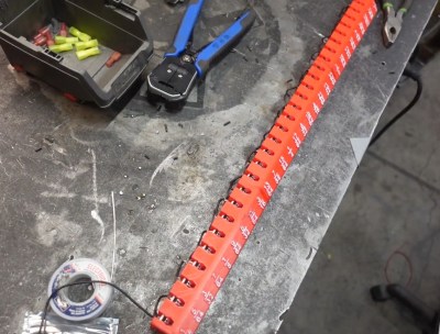
All the bits now sit in a 3D-printed index that fits the width of the drawer. [Cranktown City] tried to use daisy-chained pairs of screws as contacts behind each bit that could tell whether the bit was home or not, but too much resistance interfered with the signal. He ended up using a tiny limit switch behind each bit instead. If any bit is removed, the input signal from the index goes low, and this triggers the Arduino Nano to do two things: it lights up a strip of red LEDs behind the beautiful cut out letters on the drawer’s lip, and it starts counting upward. Every ten minutes that one or more bits are missing, the drawer complains and issues ad hominem attacks. Check out the demo and build video after the break, but not until you put your tools away. (Have you learned nothing?)

Okay, so how do you deal with thousands of jumbled drill bits? Calipers and a Python script oughta do it.

Older industrial equipment is often a great option if you’re on a budget, and you might even be able to add some premium features yourself. [Brett] from [Theoretically Practical] has done with his old MIG welder, adding premium control features with the help of an Arduino.

The main features [Brett] were after is pre-flow, post-flow, and a spot welding timer. Pre-flow starts the flow of shielding gas a moment before energizing the filler wire, while post-flow keeps the gas after the weld is complete. This reduces the chances of oxygen contaminating the welds. A spot welding timer automatically limits welding time, enabling consistent and repeatable spot welds.

The Miller S-22A wire feeder can have these features, but it requires an expensive and difficult to find control unit. All it does is time the activation of the relays that control the gas flow, power, and wire feeder, so [Brett] decided to use an Arduino instead. The welders control circuit runs and 24V, so an optoisolator receives the trigger signal, and relays are used for outputs. Potentiometers were added to the original control panel, and all the wiring was neatly fitted behind it. The upgrade worked perfectly and allowed [Brett] to increase the quality of his welds. See the video after the break for the full details.

Inverter welders can be picked up for ridiculously cheap prices, if you’re willing to live with the trade-offs. We’ve also seen some other DIY welder upgrades, on small and large machines.

We were struck by how attractive [mircemk’s] Arduino-based frequency counter looks. It also is a reasonably simple build. It can count up to 6.5 MHz which isn’t that much, but there’s a lot you can do even with that limitation.

The LED display is decidedly retro. Inside a very modern Arduino Nano does most of the work. There is a simple shaping circuit to improve the response to irregular-shaped input waveforms. We’d have probably used a single op-amp as a zero-crossing detector. Admittedly, that’s a bit more complex, but not much more and it should give better results.

There was a time when a display like this would have meant some time wiring, but with cheap Max 7219 board available, it is easy to add a display like this to nearly anything. An SPI interface takes a few wires and all the hard work and wiring is done on the module.

The code is short and sweet. There are fewer than 30 lines of code thanks to LED drivers and a frequency counter component borrowed from GitHub.

If you add a bit more hardware, 100 MHz is an easy target. There are at least three methods commonly used to measure frequency. Each has its pros and cons.

Ask anybody whose spent time standing in front of a mill or lathe and they’ll tell you that some operations can get tedious. When you need to turn down a stainless rod by 1/4″ in 0.030″ increments, you get a lot of time to reflect on why you didn’t just buy the right size stock as you crank the wheel back and forth. That’s where the lead screw comes in — most lathes have a gear-driven lead screw that can be used to actuate the z-axis ( the one which travels parallel to the axis of rotation). It’s no CNC, but this type of gearing makes life easier and it’s been around for a long time.

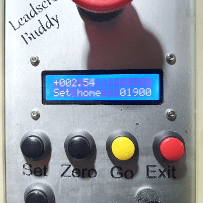
[Tony Goacher] took this idea a few steps further when he created the Leadscrew Buddy. He coupled a beautiful 1949 Myford lathe with an Arduino, a stepper motor, and a handful of buttons to add some really useful capabilities to the antique machine. By decoupling the lead screw from the lathe’s gearbox and actuating it via a stepper motor, he achieved a much more granular variable feed speed.
If that’s not enough, [Tony] used a rotary encoder to display the cutting tool’s position on a home-built Digital Readout (DRO). The pièce de résistance is a “goto” command. Once [Tony] sets a home position, he can command the z-axis to travel to a set point at a given speed. Not only does this make turning easier, but it makes the process more repeatable and yields a smoother finish on the part.

These features may not seem so alien to those used to working with modern CNC lathes, but to the vast majority of us garage machinists, [Tony]’s implementation is an exciting look at how we can step up our turning game. It also fits nicely within the spectrum of lathe projects we’ve seen here at Hackaday- from the ultra low-tech to the ludicrously-precise.

In general, the cost of electronic components and the tools used to fiddle with them have been dropping steadily over the last decade or so. But there will always be bargain-hunting hackers who are looking to get things even cheaper. Case in point, hot air rework stations. You can pick up one of the common 858D stations for as little as $40 USD, but that didn’t keep [MakerBR] from creating an Arduino controller that can be used with its spare handles.

Now to be fair, it doesn’t sound like price was the only factor here. After all, a spare 858D handle costs about half as much as the whole station, so there’s not a lot of room for improvement cost-wise. Rather, [MakerBR] says the Arduino version is designed to be more efficient and reliable than the stock hardware.

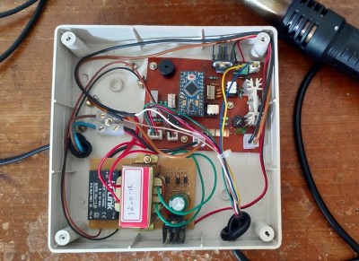
The seven wires in the handle connector have already been mapped out by previous efforts, though [MakerBR] does go over the need to verify everything matches the provided circuit diagrams as some vendors might have fiddled with the pinout. All the real magic happens in the handle itself, the controller just needs to keep an eye on the various sensors and provide the fan and heating element with appropriate control signals. An Arduino Pro Mini is more than up to the task, and a custom PCB makes for a fairly neat installation.

This isn’t the first time we’ve seen somebody replace the controller on one of these entry-level hot air stations, but because there are so many different versions floating around, you should do some careful research before cracking yours open and performing a brain transplant.

We’ve all been there. A big bag of resistors all mixed up. Maybe you bought them cheap. Maybe your neatly organized drawers spilled. Of course, you can excruciatingly read the color codes one by one. Or use a meter. But either way, it is a tedious job. [Ishann’s] solution was to build an automatic sorter that directly measures the value using a voltage divider, rather than rely on machine vision as is often the case in these projects. That means it could be modified to do matching for precise circuits (e.g., sort out resistors all marked 1K that are more than a half-percent away from one nominal value).

There is a funnel that admits one resistor at a time into a test area where it is measured. A plate at the bottom rotates depending on the measured value. In the current implementation, the resistor either falls to the left or the right. It wouldn’t be hard to make a rotating tray with compartments for different values of resistance. It looks like you have to feed the machine one resistor at a time, and automating that sounds like a trick considering how jumbled loose axial components can be. Still, its a fun project that you probably have all the parts to make.

An Arduino powers the thing. An LCD screen and display control the action. If you want some practice handling material robotically, this is a great use of servos and gravity and it does serve a practical purpose.

We have seen many variations on this, including ones that read the color code. If you ever wanted to know where the color code for resistors came from, we took a trip to the past to find out earlier this year.

Economy of scale is a wonderful thing, take the switch-mode power supply as an example. Before the rise of the PC, a decent multi-voltage, high current power supply would be pretty expensive. But PCs have meant cheap supplies and sometimes even free as you gut old PCs found in the dumpster. [OneMarcFifty] decided to make a pretty setup for a PC supply that includes a very nice color display with bargraphs and other niceties. You can see the power supply in action in the video below.

The display is a nice TFT driven by an Arduino Nano. The project uses ACS712 current sensor modules, which are nice Hall effect devices that produce a linear output for current and have over 2 KV of voltage isolation.

There are three current sensors, one for each output. Really what makes this impressive compared to many similar projects is the very nice graphical output. The GitHub has all the software as well as PCB layouts. Of course, you’ll have to adapt the enclosure to your specific power supply, but it should be pretty easy to arrange an enclosure.

With only a few buttons, the user interface is a little clunky, but no more so than a lot of other projects. You essentially only use the buttons to change the speed, scale, and resolution of the bar graphs. The output voltages are fixed and there are no current limits.

Another answer is to find a higher voltage supply and mate it with a cheap power supply module. We’ve also seen non-PC power supplies put in a PC case.

No, it’s not the kind of honeycomb you’re probably thinking of. We’re talking about the lightweight panels commonly used in aerospace applications. Apparently they’re rather prone to dents and other damage during handling, so Boeing teamed up with students from the California State University to come up with a way to automate the time-consuming repair process.

The resulting machine, which you can see in action after the break, is a phenomenal piece of engineering. But more than that, it’s an impressive use of off-the-shelf components. The only thing more fascinating than seeing this robotic machine perform its artful repairs is counting how many of its core components you’ve got laying around the shop.

Built from aluminum extrusion, powered by an Arduino Due, and spinning a Dewalt cut-off tool that looks like it was just picked it up from Home Depot, you could easily source most of the hardware yourself. Assuming you needed to automatically repair aerospace-grade honeycomb panels, anyway.

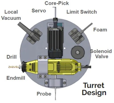
At the heart of this project is a rotating “turret” that holds all the tools required for the repair. After the turret is homed and the condition of all the cutting tools is verified, a hole is drilled into the top of the damaged cell. A small tool is then carefully angled into the hole (a little trick that is mechanical poetry in motion) to deburr the hole, and a vacuum is used to suck out any of the filings created by the previous operations. Finally a nozzle is moved into position and the void is filled with expanding foam.

Boeing says it takes up to four hours for a human to perform this same repair. Frankly, that seems a little crazy to us. But then again if we were the ones tasked with repairing a structural panel for a communications satellite or aircraft worth hundreds of millions of dollars, we’d probably take our time too. The video is obviously sped up so it’s hard to say exactly how long this automated process takes, but it doesn’t seem like it could be much more than a few minutes from start to finish.

Whether you’re using a soldering iron or a table saw, ventilation in the shop is important. Which is why [Atomic Dairy] built a monster air cleaner called the Fanboy that looks like it should be mounted under the wing of an F-15. Realizing a simple switch on the wall wouldn’t do this potent air mover justice, they decided to build a sound activated controller for it.

It’s certainly an elegant idea. The sound created once they kick on their woodworking tools would be difficult to miss by even the most rudimentary of sound-detection hardware. At the most basic level, all they needed was a way for an Arduino to throw a relay once the noise level in the room reached a specific threshold.

Of course it ended up getting a bit more complicated than that, as tends to happen with these kinds of projects. For one, the sound doesn’t directly control the solid state relay used in the fan controller. When the microphone equipped Arduino detects enough noise, it will start a timer that keeps the fan running for two hours. If the tool keeps running, then more time gets added to the clock. This ensures that the air in the room is well circulated even after the cutting and sanding is done.

[Atomic Dairy] also added a few additional features so they could have more direct control over the fan. There’s a button to manually add more time to the clock, and another button to shut it down. There’s even support for a little wireless remote control, so the fan can be operated without having to walk over to the control panel.

We’ve seen some impressive air circulation and dust collection systems over the years, but finding a way to elegantly switch them on and off has always been a problem given the wide array of tools that could be in use at any given time. Sound activation isn’t a perfect solution, but it’s certainly one we’d consider for our own shop.


  • Newsletter

    Sign up for the PlanetArduino Newsletter, which delivers the most popular articles via e-mail to your inbox every week. Just fill in the information below and submit.

  • Like Us on Facebook