If you’ve ever tried to tune a PID system, you have probably encountered equal parts overwhelming math and black magic folk wisdom. Or maybe you just let the autotune take over. If you really want to get some good intuition for motion control algorithms, PID included, nothing beats a little hands-on experimentation.
The basic setup is a potentiometer glued to a barbecue skewer with a mini-quadcopter motor and rotor on the end of it. A microcontroller reads the voltage and PWMs the propeller through a MOSFET. The goal is to have the pendulum hover stably in midair, controlled by whatever algorithms you can dream up on the controller. [Clovis]’ video demonstrates on-off and PID control of the fan. Adding a few more potentiometers (one for P, I, and D?) would make hands-on tweaking even more interactive.
In all, it’s a system that will only set you back a few bucks, but can teach you more than you’d learn in a month in college. Chances are good that you’re not going to have exactly the same brand of sardine can on hand that he did, but some improvisation is called for here.
If you don’t know why you’d like to master open-loop control algorithms, here’s one of the best advertisements that we’ve seen in a long time. But you don’t have to start out with hand-wound hundred-dollar motors, or precisely machined bits. As [Clovis] demonstrates, you can make do with a busted quadcopter and whatever you find in your kitchen.
In preparation for Makerfaire, [hwhardsoft] needed to throw together some demos. So they dug deep and produced this unique display.
The display uses two synchronized peristaltic pumps to push water and red paraffin through a tube that switches back over itself in a predictable fashion. As visible in the video after the break, the pumps go at it for a few minutes producing a seemingly random pattern. The pattern coalesces at the end into a short string of text. The text is unfortunately fairly hard to read, even on a contrasting background. Perhaps an application of UV dye could help?
Once the message has been displayed, the water and paraffin drop back into the holding tank as the next message is queued up. The oil and water separate just like expected and a pump at the level of each fluid feeds it back into the system.
We were deeply puzzled at what appeared to be an Arduino mounted on a DIN rail for use in industrial settings, but then discovered that this product is what [hwhardsoft] built the demo to sell. We can see some pretty cool variations on this technique for art displays.
In this article we review a couple of SMT prototyping boards from Schmartboard.
Introduction
Sooner or later you’ll need to use a surface-mount technology component. Just like taxes and myki* not working, it’s inevitable. When the time comes you usually have a few options – make your own PCB, then bake it in an oven or skillet pan; get the part on a demo board from the manufacturer (expensive); try and hand-solder it yourself using dead-bug wiring or try to mash it into a piece of strip board; or find someone else to do it. Thanks to the people at Schmartboard you now have another option which might cost a few dollars more but guarantees a result. Although they have boards for almost everything imaginable, we’ll look at two of them – one for QFP packages and their Arduino shield that has SOIC and SOP23-6 areas.
QFP 32-80 pin board
In our first example we’ll see how easy it is to prototype with QFP package ICs. An example of this is the Atmel ATmega328 microcontroller found on various Arduino-compatible products, for example:
Although our example has 32 pins, the board can handle up to 80-pin devices. You simply place the IC on the Schmartboard, which holds the IC in nicely due to the grooved tracks for the pins:
The tracks are what makes the Schmartboard EZ series so great – they help hold the part in, and contain the required amount of solder. I believe this design is unique to Schmartboard and when you look in their catalogue, select the “EZ” series for this technology. Moving forward, you just need some water-soluble flux:
then tack down the part, apply flux to the side you’re going to solder – then slowly push the tip of your soldering iron (set to around 750 degrees F) down the groove to the pin. For example:
Then repeat for the three other sides. That’s it. If your part has an exposed pad on the bottom, there’s a hole in the centre of the Schmartboad that you can solder into as well:
After soldering I really couldn’t believe it worked, so probed out the pins to the breakout pads on the Schmartboard to test for shorts or breaks – however it tested perfectly. The only caveat is that your soldering iron tip needs to be the same or smaller pitch than the the part you’re using, otherwise you could cause a solder bridge. And use flux! You need the flux. After soldering you can easily connect the board to the rest of your project or build around it.
This is the AD5204 four-channel digital potentiometer we used in the SPI tutorial. It sits nicely in the shield and can be easily soldered onto the board. Don’t forget the flux! Although the SMT areas have the EZ-technology, I still added a little solder of my own – with satisfactory results:
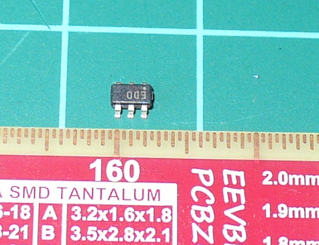
The SOT23-6 also fits well, with plenty of space for soldering it in. SOT23? Example – the ADS1110 16-bit ADC which will be the subject of a future tutorial:
Working with these tiny components is also feasible but requires a finer iron tip and a steady hand.
Once the SMT component(s) have been fitted, you can easily trace out the matching through-hole pads for further connections. The shield matches the Arduino R3 standards and includes stacking header sockets, two LEDs for general use, space and parts for an RC reset circuit, and pads to add pull-up resistors for the I2C bus:
Finally there’s also three 0805-sized parts and footprints for some practice or use. It’s a very well though-out shield and should prove useful. You can also order a bare PCB if you already have stacking headers to save money.
Conclusion
If you’re in a hurry to prototype with SMT parts, instead of mucking about – get a Schmartboard. They’re easy to use and work well. Full-sized images available on flickr.
In the meanwhile have fun and keep checking into tronixstuff.com. Why not follow things on twitter, Google+, subscribe for email updates or RSS using the links on the right-hand column? And join our friendly Google Group – dedicated to the projects and related items on this website. Sign up – it’s free, helpful to each other – and we can all learn something.
The boards used in this article were a promotional consideration supplied by Schmartboard.
In this article we review a couple of SMT prototyping boards from Schmartboard.
Introduction
Sooner or later you’ll need to use a surface-mount technology component. Just like taxes and myki* not working, it’s inevitable. When the time comes you usually have a few options – make your own PCB, then bake it in an oven or skillet pan; get the part on a demo board from the manufacturer (expensive); try and hand-solder it yourself using dead-bug wiring or try to mash it into a piece of strip board; or find someone else to do it. Thanks to the people at Schmartboard you now have another option which might cost a few dollars more but guarantees a result. Although they have boards for almost everything imaginable, we’ll look at two of them – one for QFP packages and their Arduino shield that has SOIC and SOP23-6 areas.
QFP 32-80 pin board
In our first example we’ll see how easy it is to prototype with QFP package ICs. An example of this is the Atmel ATmega328 microcontroller found on various Arduino-compatible products, for example:
Although our example has 32 pins, the board can handle up to 80-pin devices. You simply place the IC on the Schmartboard, which holds the IC in nicely due to the grooved tracks for the pins:
The tracks are what makes the Schmartboard EZ series so great – they help hold the part in, and contain the required amount of solder. I believe this design is unique to Schmartboard and when you look in their catalogue, select the “EZ” series for this technology. Moving forward, you just need some water-soluble flux:
then tack down the part, apply flux to the side you’re going to solder – then slowly push the tip of your soldering iron (set to around 750 degrees F) down the groove to the pin. For example:
Then repeat for the three other sides. That’s it. If your part has an exposed pad on the bottom, there’s a hole in the centre of the Schmartboad that you can solder into as well:
After soldering I really couldn’t believe it worked, so probed out the pins to the breakout pads on the Schmartboard to test for shorts or breaks – however it tested perfectly. The only caveat is that your soldering iron tip needs to be the same or smaller pitch than the the part you’re using, otherwise you could cause a solder bridge. And use flux! You need the flux. After soldering you can easily connect the board to the rest of your project or build around it.
This is the AD5204 four-channel digital potentiometer we used in the SPI tutorial. It sits nicely in the shield and can be easily soldered onto the board. Don’t forget the flux! Although the SMT areas have the EZ-technology, I still added a little solder of my own – with satisfactory results:
The SOT23-6 also fits well, with plenty of space for soldering it in. SOT23? Example – the ADS1110 16-bit ADC which will be the subject of a future tutorial:
Working with these tiny components is also feasible but requires a finer iron tip and a steady hand.
Once the SMT component(s) have been fitted, you can easily trace out the matching through-hole pads for further connections. The shield matches the Arduino R3 standards and includes stacking header sockets, two LEDs for general use, space and parts for an RC reset circuit, and pads to add pull-up resistors for the I2C bus:
Finally there’s also three 0805-sized parts and footprints for some practice or use. It’s a very well though-out shield and should prove useful. You can also order a bare PCB if you already have stacking headers to save money.
Conclusion
If you’re in a hurry to prototype with SMT parts, instead of mucking about – get a Schmartboard. They’re easy to use and work well. Full-sized images available on flickr.
In the meanwhile have fun and keep checking into tronixstuff.com. Why not follow things on twitter, Google+, subscribe for email updates or RSS using the links on the right-hand column? And join our friendly Google Group – dedicated to the projects and related items on this website. Sign up – it’s free, helpful to each other – and we can all learn something.
The boards used in this article were a promotional consideration supplied by Schmartboard.
Planet Arduino is, or at the moment is wishing to become, an aggregation of public weblogs from around the world written by people who develop, play, think on Arduino platform and his son. The opinions expressed in those weblogs and hence this aggregation are those of the original authors. Entries on this page are owned by their authors. We do not edit, endorse or vouch for the contents of individual posts. For more information about Arduino please visit www.arduino.cc
You are currently browsing the archives for the demo category.