This instructable will show you how to build a portable Touch Screen Oscilloscope for less than 40 U$! johnag @ instructables.com writes:
The oscilloscope is one of the most powerful electronic instruments that is available to electronics hobbyist, experimenters, and engineers. It is mainly used to measue time-varying signals. Any time you have a signal that varies with time( slowly, quickly, and /or periodically ) you can use an oscilloscope to measure it , visualize it, and to find any unexpected features in it.
Make an Oscilloscope using the SainSmart Mega2560 - [Link]
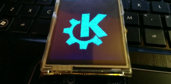
Want a nifty way to combine the craft of embroidery with electronics? The folks working on the open source Embroidermodder demoed their software by generating an embroidery of the KDE logo using a TFT screen and an Arduino.
Embroidermodder is an open source tool for generating embroidery patterns. It generates a pattern and a preview rendering of what the embroidery will look like when complete. It’s a cross-platform desktop application with a GUI, but the libembroidery library does the hard work in the background. This library was ported to Arduino to pull off the hack.
While generating pictures of embroidery with an Arduino might look neat, it isn’t too useful. However, since the library has been ported it is possible to use it to control other hardware. With the right hardware, this could be the beginning of an open source embroidery machine.
After the break, check out a video of the pattern being generated.
Learn how to use an inexpensive TFT colour touch LCD shield with your Arduino. This is chapter twenty-nine of our huge Arduino tutorial series.
Updated 07/02/2014
There are many colour LCDs on the market that can be used with an Arduino, and in this tutorial we’ll explain how to use a model that is easy to use, has a touch screen, doesn’t waste all your digital output pins – and won’t break the bank. It’s the 2.8″ TFT colour touch screen shield from Tronixlabs:
And upside down:
As you can imagine, it completely covers an Arduino Uno or compatible board, and offers a neat way to create a large display or user-interface. The display has a resolution of 320 x 240 pixels, supports up to 65536 colours and draws around 250mA of current from the Arduino’s internal 5V supply.
And unlike other colour LCDs, this one doesn’t eat up all your digital output pins – it uses the SPI bus for the display (D10~D13), and four analogue pins (A0~A3) if you use the touch sensor. However if you also use the onboard microSD socket more pins will be required.
With some imagination, existing Arduino knowledge and the explanation within you’ll be creating all sorts of displays and interfaces in a short period of time. Don’t be afraid to experiment!
Getting started
Setting up the hardware is easy – just plug the shield on your Arduino. Next, download the library bundle from here. Inside the .zip file is two folders – both which need to be copied into your …Arduino-1.0.xlibraries folder. Then you will need to rename the folder “TFT_Touch” to “TFT”. You will notice that the Arduino IDE already contains a library folder called TFT, so rename or move it.
Now let’s test the shield so you know it works, and also to have some quick fun. Upload the paint example included in the TFT library – then with a stylus or non-destructive pointer, you can select colour and draw on the LCD – as shown in this video. At this point we’d like to note that you should be careful with the screen – it doesn’t have a protective layer.
Afraid the quality of our camera doesn’t do the screen any justice, however the still image looks better:
Using the LCD
Moving on, let’s start with using the display. In your sketches the following libraries need to be included using the following lines before void setup():
… and then the TFT library is initialised in void setup()
Tft.TFTinit();
Now you can use the various functions to display text and graphics. However you first need to understand how to define colours.
Defining colours
Functions with a colour parameter can accept one of the ten ten predefined colours – RED, GREEN, BLUE, BLACK, YELLOW, WHITE, CYAN, BRIGHT_RED, GRAY1 and GRAY2, or you can create your own colour value. Colours are defined with 16-but numbers in hexadecimal form, with 5 bits for red, 6 for green and 5 for blue – all packed together. For example – in binary:
MSB > RRRRRGGGGGGRRRRR < LSB
These are called RGB565-formatted numbers – and we use these in hexadecimal format with our display. So black will be all zeros, then converted to hexadecimal; white all ones, etc. The process of converting normal RGB values to RGB565 would give an aspirin a headache, but instead thanks to Henning Karlsen you can use his conversion tool to do the work for you. Consider giving Henning a donation for his efforts.
Displaying text
There are functions to display characters, strings of text, integers and float variables:
Tft.drawChar(char, x, y, size, colour); // displays single character variables
Tft.drawString(string, x, y, size, colour); // displays arrays of characters
Tft.drawNumber(integer, x, y, size, colour); // displays integers
Tft.drawFloat(float, x, y, size, colour); // displays floating-point numbers
In each of the functions, the first parameter is the variable or data to display; x and y are the coordinates of the top-left of the first character being displayed; and colour is either the predefined colour as explained previously, or the hexadecimal value for the colour you would like the text to be displayed in – e.g. 0xFFE0 is yellow.
The drawFloat() function is limited to two decimal places, however you can increase this if necessary. To do so, close the Arduino IDE if running, open the file TFTv2.cpp located in the TFT library folder – and search for the line:
INT8U decimal=2;
… then change the value to the number of decimal places you require. We have set ours to four with success, and the library will round out any more decimal places. To see these text display functions in action, upload the following sketch:
There are functions to draw individual pixels, circles, filled circles, lines, rectangles and filled rectangles. With these and a little planning you can create all sorts of images and diagrams. The functions are:
Tft.setPixel(x, y, COLOUR);
// set a pixel at x,y of colour COLOUR
Tft.drawLine(x1, y1, x2, y2, COLOUR);
// draw a line from x1, y1 to x2, y2 of colour COLOUR
Tft.drawCircle(x, y, r, COLOUR);
// draw a circle with centre at x, y and radius r of colour COLOUR
Tft.fillCircle(x, y, r, COLOUR);
// draw a filled circle with centre at x, y and radius r of colour COLOUR
Tft.drawRectangle(x1, y1, x2, y2 ,COLOUR);
// draw a rectangle from x1, y1 (top-left corner) to x2, y2 (bottom-right corner) of colour COLOUR
Tft.Tft.fillRectangle(x1, y1, x2, y2 ,COLOUR);
// draw a filled rectangle from x1, y1 (top-left corner) to x2, y2 (bottom-right corner) of colour COLOUR
The following sketch demonstrates the functions listed above:
#include <stdint.h>
#include <TFTv2.h>
#include <SPI.h>
int x, y, x1, x2, y1, y2, r;
void setup()
{
randomSeed(analogRead(0));
Tft.TFTinit();
}
void loop()
{
// random pixels
for (int i=0; i<500; i++)
{
y=random(320);
x=random(240);
Tft.setPixel(x, y, YELLOW);
delay(5);
}
delay(1000);
Tft.fillScreen(); // clear screen
// random lines
for (int i=0; i<50; i++)
{
y1=random(320);
y2=random(320);
x1=random(240);
x2=random(240);
Tft.drawLine(x1, y1, x2, y2, RED);
delay(10);
}
delay(1000);
Tft.fillScreen(); // clear screen
// random circles
for (int i=0; i<50; i++)
{
y=random(320);
x=random(240);
r=random(50);
Tft.drawCircle(x, y, r, BLUE);
delay(10);
}
delay(1000);
Tft.fillScreen(); // clear screen
// random filled circles
for (int i=0; i<10; i++)
{
y=random(320);
x=random(240);
r=random(50);
Tft.fillCircle(x, y, r, GREEN);
delay(250);
Tft.fillCircle(x, y, r, BLACK);
}
delay(1000);
Tft.fillScreen(); // clear screen
// random rectangles
for (int i=0; i<50; i++)
{
y1=random(320);
y2=random(320);
x1=random(240);
x2=random(240);
Tft.drawRectangle(x1, y1, x2, y2, WHITE);
delay(10);
}
delay(1000);
Tft.fillScreen(); // clear screen
// random filled rectangles
for (int i=0; i<10; i++)
{
y1=random(320);
y2=random(320);
x1=random(240);
x2=random(240);
Tft.fillRectangle(x1, y1, x2, y2, RED);
delay(250);
Tft.fillRectangle(x1, y1, x2, y2, BLACK);
}
delay(1000);
Tft.fillScreen(); // clear screen
}
The touch screen operates in a similar manner to the other version documented earlier, in that it is a resistive touch screen and we very quickly apply voltage to one axis then measure the value with an analogue pin, then repeat the process for the other axis.
You can use the method in that chapter, however with our model you can use a touch screen library, and this is included with the library .zip file you downloaded at the start of this tutorial.
The library does simplify things somewhat, so without further ado upload the touchScreen example sketch included with the library. Open the serial monitor then start touching the screen. The coordinates of the area over a pixel being touch will be returned, along with the pressure – as shown in this video.
Take note of the pressure values, as these need to be considered when creating projects. If you don’t take pressure into account, there could be false positive touches detected which could cause mayhem in your project.
Now that you have a very simple method to determine the results of which part of the screen is being touched – you can create sketches to take action depending on the touch area. Recall from the example touch sketch that the x and y coordinates were mapped into the variables p.x and p.y, with the pressure mapped to p.z. You should experiment with your screen to determine which pressure values work for you.
In the following example, we don’t trigger a touch unless the pressure value p.z is greater than 300. Let’s create a simple touch-switch, with one half of the screen for ON and the other half for OFF. Here is the sketch:
#include <stdint.h>
#include <TFTv2.h>
#include <SPI.h>
#include <TouchScreen.h>

// determine the pins connected to the touch screen hardware
// A0~A3
#define YP A2   // must be an analog pin, use "An" notation!
#define XM A1   // must be an analog pin, use "An" notation!
#define YM 14   // can be a digital pin, this is A0
#define XP 17   // can be a digital pin, this is A3

#define TS_MINX 116*2
#define TS_MAXX 890*2
#define TS_MINY 83*2
#define TS_MAXY 913*2

// For better pressure precision, we need to know the resistance
// between X+ and X- Use any multimeter to read it
// The 2.8" TFT Touch shield has 300 ohms across the X plate
TouchScreen ts = TouchScreen(XP, YP, XM, YM);

void setup()
{
  Serial.begin(9600);
  Tft.TFTinit();
  Tft.fillScreen(); // clear screen
}

void loop()
{
  // a point object holds x y and z coordinates
  Point p = ts.getPoint();
  p.x = map(p.x, TS_MINX, TS_MAXX, 0, 240);
  p.y = map(p.y, TS_MINY, TS_MAXY, 0, 320);
  Serial.println(p.y);
  if (p.y < 160 && p.z > 300) // top half of screen?
  {
    // off
    Tft.fillCircle(120, 160, 100, BLACK);
    Tft.drawCircle(120, 160, 100, BLUE);
  } else if (p.y >= 160 && p.z > 300)
  {
    // on
    Tft.fillCircle(120, 160, 100, BLUE);
  }
}
What’s happening here? We divided the screen into two halves (well not physically…) and consider any touch with a y-value of less than 160 to be the off area, and the rest of the screen to be the on area. This is tested in the two if functions – which also use an and (“&&”)to check the pressure. If the pressure is over 300 (remember, this could be different for you) – the touch is real and the switch is turned on or off.
We feel this warrants a separate tutorial, however if you can’t wait – check out the demo sketch which includes some example image files to use.
Conclusion
By now I hope you have the answer to “how do you use a touch screen LCD with Arduino?” and had some fun learning with us. You can get your LCD from Tronixlabs. And if you enjoyed this article, or want to introduce someone else to the interesting world of Arduino – check out my book (now in a third printing!) “Arduino Workshop”.
Have fun and keep checking into tronixstuff.com. Why not follow things on twitter, Google+, subscribe for email updates or RSS using the links on the right-hand column, or join our forum – dedicated to the projects and related items on this website. Sign up – it’s free, helpful to each other – and we can all learn something.
arduino, LCD, microSD, TFTComments Off on Your Image on an Arduino! – TFT LCD Screen Guide
Qtechknow @ instructables.com
Have you ever heard of TFT LCD screens? They are great ways to display information from your Arduino, or display pictures. The Arduino team just released an official TFT LCD screen with their new Robot at Maker Faire 2013. It’s very easy to get started with!! This tutorial will show you how to get the LCD up and running, load information from the SD card, and make a few simple projects.
The TFT LCD screen is a great way to detach your computer, and have the Arduino relay information that you need to know onto the LCD. A great part of the LCD is that it has a built in microSD card socket. You can store images on the microSD card socket, and even some text!
Your Image on an Arduino! – TFT LCD Screen Guide - [Link]
These TFT LCD screens can be picked up on eBay for a few dollars. But they’re more suited for 16-bit microcontrollers which operate at 3.3V levels. His adapter board, which plugs directly into the Mega’s dual-row pin header, makes it easier to control these with an 8-bit chip that is running at 5V.
There’s a couple of things that make this happen. First off, he’s included level converter chips to managed the 3.3V/5V issues. Second, he uses latch chips to translate eight pins on the Arduino Mega to sixteen pins on the display. Those chips have a latch pin which holds the output values in memory while the input pins are changed. He manages to drive the latch on just one of the chips using the chip select (CS) line called for by the LCD protocol. This means you don’t lose any extra pins.
The fact that you can build a cellphone around an Arduino is pretty neat. But we’re drawn to this project more as a testament to the advancement of hobby electronics. An [Average Joe] can build this thing with a minimum or background knowledge and without breaking the bank. Wow.
Of course this isn’t the first DIY cellphone we’ve come across. One of our favorites is this one which resides on a home etched PCB. There was even another Arduino offering with similar components back in September. But the one seen above really pulls it all together into a package that is usable for everyday life. The components include and Arduino Uno, GPRS shield from Seeed Studios, a TFT touch screen, Lithium battery and charging circuit, and a few other bobbles. All of it is mounted inside of a 3D printed case.
A simple phone calls for a simple UI and that’s included as well. The main menu has two buttons, one for placing a call, the other for sending a text. From there you get the virtual keypad seen above for typing out the phone number or composing a message.
In conjunction with the release of the new version of the Arduino IDE and the Arduino Robot, we’re also putting out a TCT LCD screen. The screen was developed in conjunction with Complubot and the library relies on the Adafruit GFX and ST7735 libraries.
The Arduino specific library, named TFT, extends the Adafruit libraries to support more Processing-like methods. You can write text, draw shapes, and show bitmap images on the screen in a way that should be familiar to users of Processing.
The screen works well with all types of Arduinos with a little bit of wiring, and fits perfectly in the Esplora and Robot sockets. In addition to all this other goodness, there’s a SD card slot on the back for storing pictures and other data.
Learn how to use inexpensive ILI9325 colour TFT LCD modules in chapter fifty of a series originally titled “Getting Started/Moving Forward with Arduino!” by John Boxall – A tutorial on the Arduino universe. The first chapter is here, the complete series is detailed here.
Introduction
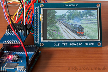
Colour TFT LCD modules just keep getting cheaper, so in this tutorial we’ll show you how to get going with some of the most inexpensive modules we could find. The subject of our tutorial is a 2.8″ 240 x 320 TFT module with the ILI9325 LCD controller chip. If you look in ebay this example should appear pretty easily, here’s a photo of the front and back to help identify it:
There is also the line “HY-TFT240_262k HEYAODZ110510″ printed on the back of the module. They should cost less than US$10 plus shipping. Build quality may not be job number one at the factory so order a few, however considering the cost of something similar from other retailers it’s cheap insurance. You’ll also want sixteen male to female jumper wires to connect the module to your Arduino.
Getting started
To make life easier we’ll use an Arduino library “UTFT” written for this and other LCD modules. It has been created by Henning Karlsen and can be downloaded from his website. If you can, send him a donation – this library is well worth it. Once you’ve downloaded and installed the UTFT library, the next step is to wire up the LCD for a test.
Run a jumper from the following LCD module pins to your Arduino Uno (or compatible):
DB0 to DB7 > Arduino D0 to D7 respectively
RD > 3.3 V
RSET > A2
CS > A3
RW > A4
RS > A5
backlight 5V > 5V
backlight GND > GND
Then upload the following sketch – Example 50.1. You should be presented with the following on your display:
If you’re curious, the LCD module and my Eleven board draws 225 mA of current. If that didn’t work for you, double-check the wiring against the list provided earlier. Now we’ll move forward and learn how to display text and graphics.
Sketch preparation
You will always need the following before void setup():
#include "UTFT.h"
UTFT myGLCD(ILI9325C,19,18,17,16); // for Arduino Uno
and in void setup():
myGLCD.InitLCD(orientation);
myGLCD.clrScr();
with the former command, change orientation to either LANDSCAPE to PORTRAIT depending on how you’ll view the screen. You may need further commands however these are specific to features that will be described below. The function .clrScr() will clear the screen.
Displaying Text
There are three different fonts available with the library. To use them add the following three lines before void setup():
Where red, green and blue are values between zero and 255. So if you want white use 255,255,255 etc. For some named colours and their RGB values, click here. To select the required font, use one of the following:
myGLCD.setFont(SmallFont); // Allows 20 rows of 40 characters
myGLCD.setFont(BigFont); // Allows 15 rows of 20 characters
myGLCD.setFont(SevenSegNumFont); // allows display of 0 to 9 over four rows
Now to display the text use the function:
myGLCD.print("text to display",x, y);
where text is what you’d like to display, x is the horizontal alignment (LEFT, CENTER, RIGHT) or position in pixels from the left-hand side of the screen and y is the starting point of the top-left of the text. For example, to start at the top-left of the display y would be zero. You can also display a string variable instead of text in inverted commas.
You can see all this in action with the following sketch – Example 50.2, which is demonstrated in the following video:
Furthremore, you can also specify the angle of display, which gives a simple way of displaying text on different slopes. Simply add the angle as an extra parameter at the end:
myGLCD.print("Hello, world", 20, 20, angle);
Again, see the following sketch – Example 50.2a, and the results below:
Displaying Numbers
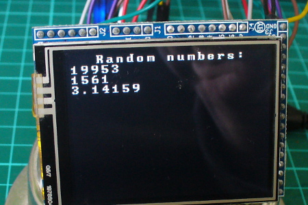
Although you can display numbers with the text functions explained previously, there are two functions specifically for displaying integers and floats.
You can see these functions in action with the following sketch – Example 50.3, with an example of the results below:
Displaying Graphics
There’s a few graphic functions that can be used to create required images. The first is:.
myGLCD.fillScr(red, green, blue);
which is used the fill the screen with a certain colour. The next simply draws a pixel at a specified x,y location:
myGLCD.drawPixel(x,y);
Remember that the top-left of the screen is 0,0. Moving on, to draw a single line, use:
myGLCD.drawLine(x1,0,x2,239);
where the line starts at x1,y1 and finishes at x2,y2. Need a rectangle? Use:
myGLCD.drawRect(x1,y2,x2,y2); // for open rectangles
myGLCD.fillRect(x1,y2,x2,y2); // for filled rectangles
where the top-left of the rectangle is x1,y1 and the bottom-right is x2, y2. You can also have rectangles with rounded corners, just use:
myGLCD.drawRoundRect(x1,y2,x2,y2); // for open rectangles
myGLCD.fillRoundRect(x1,y2,x2,y2); // for filled rectangles
instead. And finally, circles – which are quite easy. Just use:
myGLCD.drawCircle(x,y,r); // draws open circle
myGLCD.fillCircle(x,y,r); // draws a filled circle
where x,y are the coordinates for the centre of the circle, and r is the radius. For a quick demonstration of all the graphic functions mentioned so far, see Example 50.4 – and the following video:
Displaying bitmap images
If you already have an image in .gif, .jpg or .png format that’s less than 300 KB in size, this can be displayed on the LCD. To do so, the file needs to be converted to an array which is inserted into your sketch. Let’s work with a simple example to explain the process. Below is our example image:
Save the image of the puppy somewhere convenient, then visit this page. Select the downloaded file, and select the .c and Arduino radio buttons, then click “make file”. After a moment or two a new file will start downloading. When it arrives, open it with a text editor – you’ll see it contains a huge array and another #include statement – for example:
Past the #include statement and the array into your sketch above void setup(). After doing that, don’t be tempted to “autoformat” the sketch in the Arduino IDE. Now you can use the following function to display the bitmap on the LCD:
myGLCD.drawBitmap(x,y,width,height, name, scale);
Where x and y are the top-left coordinates of the image, width and height are the … width and height of the image, and name is the name of the array. Scale is optional – you can double the size of the image with this parameter. For example a value of two will double the size, three triples it – etc. The function uses simple interpolation to enlarge the image, and can be a clever way of displaying larger images without using extra memory. Finally, you can also display the bitmap on an angle – using:
where angle is the angle of rotation and cx/cy are the coordinates for the rotational centre of the image.
The bitmap functions using the example image have been used in the following sketch – Example 50.5, with the results in the following video:
Unfortunately the camera doesn’t really do the screen justice, it looks much better with the naked eye.
What about the SD card socket and touch screen?
The SD socket didn’t work, and I won’t be working with the touch screen at this time.
Conclusion
So there you have it – an incredibly inexpensive and possibly useful LCD module. Thank you to Henning Karlsen for his useful library, and if you found it useful – send him a donation via his page.
In the meanwhile have fun and keep checking into tronixstuff.com. Why not follow things on twitter, Google+, subscribe for email updates or RSS using the links on the right-hand column? And join our friendly Google Group – dedicated to the projects and related items on this website. Sign up – it’s free, helpful to each other – and we can all learn something.
Learn how to use inexpensive ILI9325 colour TFT LCD modules in chapter fifty of a series originally titled “Getting Started/Moving Forward with Arduino!” by John Boxall – A tutorial on the Arduino universe. The first chapter is here, the complete series is detailed here.
Introduction
Colour TFT LCD modules just keep getting cheaper, so in this tutorial we’ll show you how to get going with some of the most inexpensive modules we could find. The subject of our tutorial is a 2.8″ 240 x 320 TFT module with the ILI9325 LCD controller chip. If you look in ebay this example should appear pretty easily, here’s a photo of the front and back to help identify it:
There is also the line “HY-TFT240_262k HEYAODZ110510″ printed on the back of the module. They should cost less than US$10 plus shipping. Build quality may not be job number one at the factory so order a few, however considering the cost of something similar from other retailers it’s cheap insurance. You’ll also want sixteen male to female jumper wires to connect the module to your Arduino.
Getting started
To make life easier we’ll use an Arduino library “UTFT” written for this and other LCD modules. It has been created by Henning Karlsen and can be downloaded from his website. If you can, send him a donation – this library is well worth it. Once you’ve downloaded and installed the UTFT library, the next step is to wire up the LCD for a test.
Run a jumper from the following LCD module pins to your Arduino Uno (or compatible):
DB0 to DB7 > Arduino D0 to D7 respectively
RD > 3.3 V
RSET > A2
CS > A3
RW > A4
RS > A5
backlight 5V > 5V
backlight GND > GND
Then upload the following sketch – Example 50.1. You should be presented with the following on your display:
If you’re curious, the LCD module and my Eleven board draws 225 mA of current. If that didn’t work for you, double-check the wiring against the list provided earlier. Now we’ll move forward and learn how to display text and graphics.
Sketch preparation
You will always need the following before void setup():
#include "UTFT.h"
UTFT myGLCD(ILI9325C,19,18,17,16); // for Arduino Uno
and in void setup():
myGLCD.InitLCD(orientation);
myGLCD.clrScr();
with the former command, change orientation to either LANDSCAPE to PORTRAIT depending on how you’ll view the screen. You may need further commands however these are specific to features that will be described below. The function .clrScr() will clear the screen.
Displaying Text
There are three different fonts available with the library. To use them add the following three lines before void setup():
Where red, green and blue are values between zero and 255. So if you want white use 255,255,255 etc. For some named colours and their RGB values, click here. To select the required font, use one of the following:
myGLCD.setFont(SmallFont); // Allows 20 rows of 40 characters
myGLCD.setFont(BigFont); // Allows 15 rows of 20 characters
myGLCD.setFont(SevenSegNumFont); // allows display of 0 to 9 over four rows
Now to display the text use the function:
myGLCD.print("text to display",x, y);
where text is what you’d like to display, x is the horizontal alignment (LEFT, CENTER, RIGHT) or position in pixels from the left-hand side of the screen and y is the starting point of the top-left of the text. For example, to start at the top-left of the display y would be zero. You can also display a string variable instead of text in inverted commas.
You can see all this in action with the following sketch – Example 50.2, which is demonstrated in the following video:
Furthremore, you can also specify the angle of display, which gives a simple way of displaying text on different slopes. Simply add the angle as an extra parameter at the end:
myGLCD.print(“Hello, world”, 20, 20, angle);
Again, see the following sketch – Example 50.2a, and the results below:
Displaying Numbers
Although you can display numbers with the text functions explained previously, there are two functions specifically for displaying integers and floats.
You can see these functions in action with the following sketch – Example 50.3, with an example of the results below:
Displaying Graphics
There’s a few graphic functions that can be used to create required images. The first is:
myGLCD.fillScr(red, green, blue);
which is used the fill the screen with a certain colour. The next simply draws a pixel at a specified x,y location:
myGLCD.drawPixel(x,y);
Remember that the top-left of the screen is 0,0. Moving on, to draw a single line, use:
myGLCD.drawLine(x1,0,x2,239);
where the line starts at x1,y1 and finishes at x2,y2. Need a rectangle? Use:
myGLCD.drawRect(x1,y2,x2,y2); // for open rectangles
myGLCD.fillRect(x1,y2,x2,y2); // for filled rectangles
where the top-left of the rectangle is x1,y1 and the bottom-right is x2, y2. You can also have rectangles with rounded corners, just use:
myGLCD.drawRoundRect(x1,y2,x2,y2); // for open rectangles
myGLCD.fillRoundRect(x1,y2,x2,y2); // for filled rectangles
instead. And finally, circles – which are quite easy. Just use:
myGLCD.drawCircle(x,y,r); // draws open circle
myGLCD.fillCircle(x,y,r); // draws a filled circle
where x,y are the coordinates for the centre of the circle, and r is the radius. For a quick demonstration of all the graphic functions mentioned so far, see Example 50.4 – and the following video:
Displaying bitmap images
If you already have an image in .gif, .jpg or .png format that’s less than 300 KB in size, this can be displayed on the LCD. To do so, the file needs to be converted to an array which is inserted into your sketch. Let’s work with a simple example to explain the process. Below is our example image:
Save the image of the puppy somewhere convenient, then visit this page. Select the downloaded file, and select the .c and Arduino radio buttons, then click “make file”. After a moment or two a new file will start downloading. When it arrives, open it with a text editor – you’ll see it contains a huge array and another #include statement – for example:
Past the #include statement and the array into your sketch above void setup(). After doing that, don’t be tempted to “autoformat” the sketch in the Arduino IDE. Now you can use the following function to display the bitmap on the LCD:
myGLCD.drawBitmap(x,y,width,height, name, scale);
Where x and y are the top-left coordinates of the image, width and height are the … width and height of the image, and name is the name of the array. Scale is optional – you can double the size of the image with this parameter. For example a value of two will double the size, three triples it – etc. The function uses simple interpolation to enlarge the image, and can be a clever way of displaying larger images without using extra memory. Finally, you can also display the bitmap on an angle – using:
where angle is the angle of rotation and cx/cy are the coordinates for the rotational centre of the image.
The bitmap functions using the example image have been used in the following sketch – Example 50.5, with the results in the following video:
Unfortunately the camera doesn’t really do the screen justice, it looks much better with the naked eye.
What about the SD card socket and touch screen?
The SD socket didn’t work, and I won’t be working with the touch screen at this time.
Conclusion
So there you have it – an incredibly inexpensive and possibly useful LCD module. Thank you to Henning Karlsen for his useful library, and if you found it useful – send him a donation via his page.
In the meanwhile have fun and keep checking into tronixstuff.com. Why not follow things on twitter, Google+, subscribe for email updates or RSS using the links on the right-hand column? And join our friendly Google Group – dedicated to the projects and related items on this website. Sign up – it’s free, helpful to each other – and we can all learn something.
Planet Arduino is, or at the moment is wishing to become, an aggregation of public weblogs from around the world written by people who develop, play, think on Arduino platform and his son. The opinions expressed in those weblogs and hence this aggregation are those of the original authors. Entries on this page are owned by their authors. We do not edit, endorse or vouch for the contents of individual posts. For more information about Arduino please visit www.arduino.cc
You are currently browsing the archives for the TFT category.