Last week we published our gift guides presenting you a list of products available on the Arduino Store and divided by topic for Kids and people interested in IoT, Home Lab and Fashion Tech.
Now we’d like to give you some suggestions for gift ideas fitting anyone’s piggy bank:
The Merry Resistivities Set contains all the materials you need to make three flashing greeting cards using Electric Paint. This fun activity is great for makers of all ages.
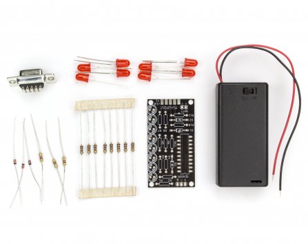
A simple POV toy for beginners who are looking to learn how to solder, how to program microcontrollers, or make LED blinky toys. Because the programmer is built into the kit, one does not need a special “microcontroller programmer”.
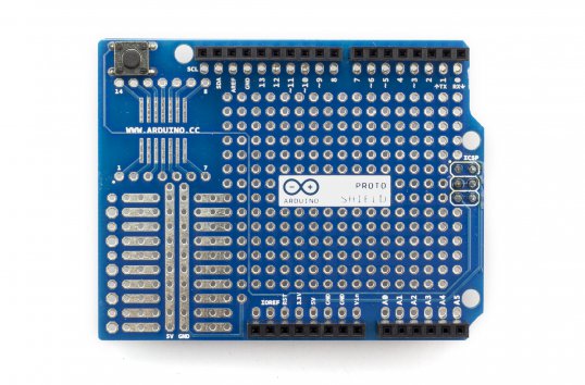
The Arduino Prototyping Shield makes it easy for you to design custom circuits for your next Arduino project. You can solder parts to the prototyping area to create your project with extra connections for all of the Arduino I/O pins.
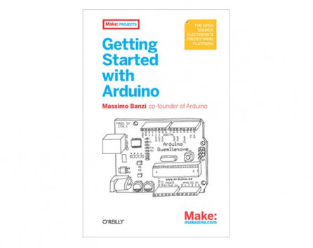
This classic book to start tinkering with Arduino gives you lots of ideas for projects and helps you work with them right away. From getting organized to putting the final touches on your prototype, all the information you need is here!
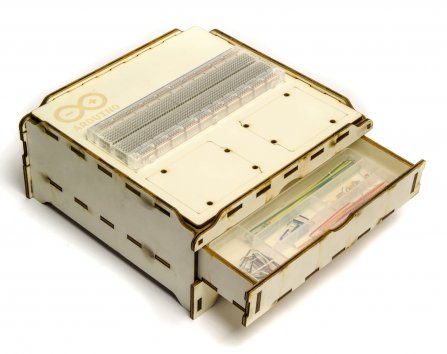
This lasercut (in Officine Arduino), wooden case is perfect to host your project and store electronic parts. It features two drawers, a confortable surface for a standard breadboard and the space for two Arduinos to be hooked up. It’s stackable, perfect for teaching material or group work.
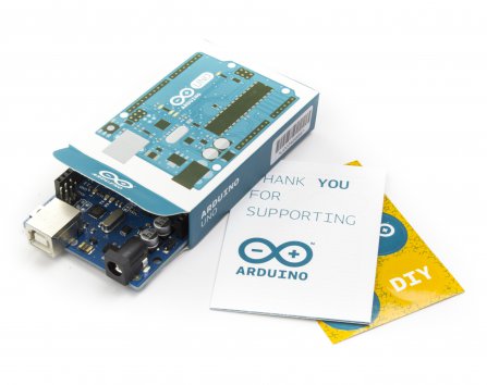
If you want to make any beginner happy, this is the perfect gift. “Uno” means “One” in Italian and is named to mark the upcoming release of Arduino 1.0. The Uno and version 1.0 will be the reference versions of Arduino, moving forward. The Uno is the latest in a series of USB Arduino boards, and the reference model for the Arduino platform.
Lumi is a new DIY alternative to screen printing.The process works on cotton, linen, silk, rayon, canvas, and any other natural & absorbent fiber. Once finished, your print is permanent and can be machine washed without fading.
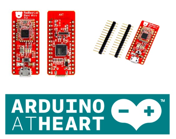
Arduino At Heart Blend Micro is RedBearLab first integrated developement board, they have “blend”ed Arduino with Bluetooth 4.0 Low Energy (aka BLE or Bluetooth Smart) into a single board. It is targeted for makers to develop low power Internet-Of-Things (IoT) projects quickly and easily.
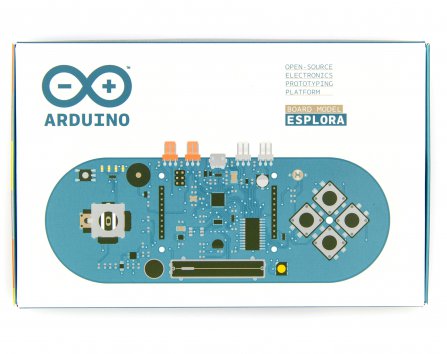
The Arduino Esplora is a ready-to-use, easy-to-hold controller that lets you explore the infinitive possibilities you have in the world of sensor and actuators, without having to deal with breadboards, soldering or cable. There is no limits to the sensors applications! Adding a LCD module you can make your personal videogame!
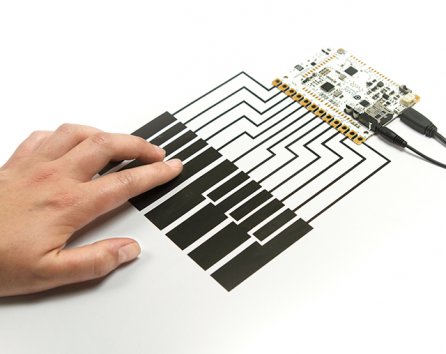
Touch Board can turn almost any material or surface into a sensor by connecting it to one of its 12 electrodes, using conductive paint or anything conductive. It’s designed as an easy-to-use platform for a huge range of projects, whether it’s painting a lightswitch on your wall, making a paper piano or something nobody’s thought of yet.
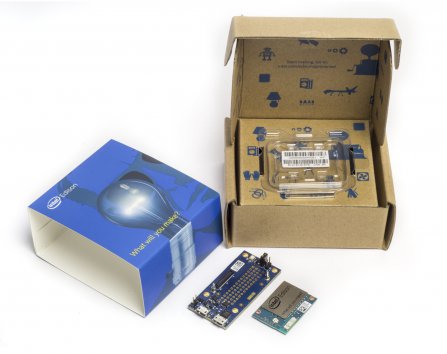
The Intel Edison is an ultra small computing platform that will change the way you look at embedded electronics. This kit also includes a Arduino Breakout, which essentially gives your Edison the ability to interface with Arduino shields or any board with the Arduino footprint.
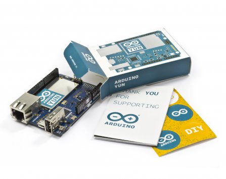
Arduino with onboard Wi-Fi connectivity and a Linux computer. Great for IoT projects. The Arduino YÚN is the combination of a classic Arduino Leonardo (based on the Atmega32U4 processor) with a WiFi system-on-chip running OpenWrt-Yun.
Remember
FREE SHIPPING to European Union for all orders over €100 (below 3Kg overall weight). Should you need delivery by Dec 24th, we strongly advise you to place the order before Dec 15th. FREE SHIPPING is available from Dec. 2nd 2014 until Jan 6th 2015. Read more about the shipping policy.
Regardless of your budget, time and flair, there’s a perfect pick to put under your friends’ and relatives’ tree this year. We created a series of Gift Guides to help you be more relaxed and efficient in finding the best solution for all. You can check below and find out also some good news regarding free shipping (check at the end of the blogpost!)
Kids
Winter holidays and Christmas is the time most of the people focus on kids and family in the most broader sense. And never like today we have the chance to make a present and open up new worlds to the little ones.
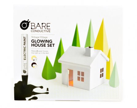
Yes. I’m talking about the experience you have playing with littleBits Base Kit for the first time. It’s an excitement for electronics you can share with kids and teenagers also happening when playing with Bare Conductive Pen, Voltage Village Glowing House or the TV-B-Gone Kit designed to shut off any TV. They are like an entire universe hiding into a game box!
IoT and connected devices has absolutely exploded in the past year, so if you’ve got coders and startuppers on your gift list, these ideas could save your time. In this gift guide you’ll find a selected list for different tastes and for sure there’s something for everyone.
Some people say that in the future our homes will be fully automated, with refrigerators ordering your milk when it’s over, and other gizmos enabling the materialisation of a truly smart home. Is this what we want? Probably we’re not sure yet but there are a few tools that you can buy for your house that will get you and your friends to feel like what it means to have a home lab.
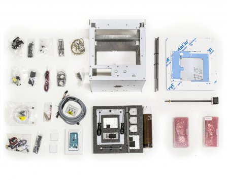
Starting from a Materia 101 kit to 3d print cool decorations for Christmas and you can take your holiday time to build it with the help of some friends. Or use some quite days to dive in the world of electronics exploring Make Electronics book by Charles Platt or tinkering with some components you’ve never had time to explore like the Arduino Wireless SD Proto Shield or the Tinkerkit DMX Receiver .
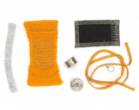
Fashion and tech are closer than ever these days. Textile sensors make every interactive project comfortable to wear and easy to prototype. Soft potentiometers, Textile push buttons, Stretch sensors connected to an Arduino Lilypad are the best components to explore this promising field. You can begin with the Open Softwear book 2nd edition plus the Easy Wearable Kit and then move forward with yellow EL-Wires to brighten your winter. If you want to explore new approaches not related with electronics, then try the DIY alternative to print fabrics using light with Lumi KIT Red or Blu.
Arduino Store is now offering FREE SHIPPING to Europe via GLS for all orders over €100, below 3 Kg overall weight. GLS delivery will take 4-5 working days to reach you. In December, this may take longer due to end-of-the-year seasonality. Should you need delivery by Dec. 24th, we strongly advice you to place the order before Dec. 15th. Learn more about shipping
Use the Texas Instruments TLC5940 16-Channel LED Driver IC with Arduino in Chapter 57 of our Arduino Tutorials. The first chapter is here, the complete series is detailed here.
Introduction
Today we are going to examine the Texas Instruments TLC5940 16-channel LED driver IC. Our reason for doing this is to demonstrate another, easier way of driving many LEDs – and also servos. First up, here is a few examples of the TLC5940
The TLC5940 is available in the DIP version above, and also surface-mount. It really is a convenient part, allowing you to adjust the brightness of sixteen individual LEDs via PWM (pulse-width modulation) – and you can also daisy-chain more than one TLC5940 to control even more.
During this tutorial we’ll explain how to control one or more TLC5940 ICs with LEDs and also look at controlling servos. At this point, please download a copy of the TLC5940_data_sheet (.pdf) as you will refer to it through this process. Furthermore, please download and install the TLC5940 Arduino library by Alex Leone which can be found here. If you’re not sure how to install a library, click here.
Build a TLC5940 demonstration circuit
The following circuit is the minimum required to control sixteen LEDs from your Arduino or compatible. You can use it to experiment with various functions and get an idea of what is possible. You will need:
16 normal, everyday LEDs that can have a forward current of up to 20 mA
a 2 kΩ resistor (give or take 10%)
a 0.1uF ceramic and a 4.7uF electrolytic capacitor
Take note of the LED orientation – and remember the TLC5940 is a common-anode LED driver – so all the LED anodes are connected together and then to 5V:
For this particular circuit, you won’t need an external 5V power supply – however you may need one in the future. The purpose of the resistor is to control the amount of current that can flow through the LEDs. The required resistor value is calculated with the following formula:
R = 39.06 / Imax
where R (in Ohms) is the resistor value and Imax (in Amps) is the maximum amount of current you want to flow through the LEDs. For example, if you have LEDs with a 20 mA forward current – the resistor calculation would be:
R = 39.06 / 0.02 = 1803 Ohms.
Once you have the circuit assembled – open up the Arduino IDE and upload the sketch BasicUse.pde which is in the example folder for the TLC5940 library. You should be presented with output similar to what is shown in the following video:
Controlling the TLC5940
Now that the circuit works, how do we control the TLC5940? First, the mandatory functions – include the library at the start of the sketch with:
#include "Tlc5940.h"
and then initialise the library by placing the following into void setup():
Tlc.init(x);
x is an optional parameter – if you want to set all the channels to a certain brightness as soon as the sketch starts, you can insert a value between 0 and 4095 for x in the Tlc.init() function.
Now to turn a channel/LED on or off. Each channel is numbered from 0 to 15, and each channel’s brightness can be adjusted between 0 and 4095.
This is a two-part process…
First – use one or more of the following functions to set up the required channels and respective brightness (PWM level):
Tlc.set(channel, brightness);
For example, if you wanted to have the first three channels on at full brightness, use:
The second part is to use the following to update the TLC5940 with the required instructions from part one:
Tlc.update();
If you want to turn off all channels at once, simply use:
Tlc.clear();
You don’t need to call a TLC.update() after the clear function. The following is a quick example sketch that sets the brightness/PWM values of all the channels to different levels:
#include "Tlc5940.h"
void setup()
{
  Tlc.init(0); // initialise TLC5940 and set all channels off
}

void loop()
{
  for (int i = 0; i < 16; i++)
  {
    Tlc.set(i, 1023);
  }
  Tlc.update();
  delay(1000);
  for (int i = 0; i < 16; i++)
  {
    Tlc.set(i, 2046);
  }
  Tlc.update();
  delay(1000);
  for (int i = 0; i < 16; i++)
  {
    Tlc.set(i, 3069);
  }
  Tlc.update();
  delay(1000);
  for (int i = 0; i < 16; i++)
  {
    Tlc.set(i, 4095);
  }
  Tlc.update();
  delay(1000);
}
The ability to control individual brightness for each channel/LED can also be useful when controlling RGB LEDs – you can then easily select required colours via different brightness levels for each element.
Using two or more TLC5940s
You can daisy-chain quite a few TLC5940s together to control more LEDs. First – wire up the next TLC5940 to the Arduino as shown in the demonstration circuit – except connect the SOUT pin (17) of the first TLC5940 to the SIN pin (26) of the second TLC5940 – as the data travels from the Arduino, through the first TLC5940 to the second and so on. Then repeat the process if you have a third, etc. Don’t forget the resisotr that sets the current!
Next, open the file tlc_config.h located in the TLC5940 library folder. Change the value of NUM_TLCS to the number of TLC5940s you have connected together, then save the file and also delete the file Tlc5940.oalso located in the same folder. Finally restart the IDE. You can then refer to the channels of the second and further TLC5940 sequentially from the first. That is, the first is 0~15, the second is 16~29, and so on.
Controlling servos with the TLC5940
As the TLC5940 generates PWM (pulse-width modulation) output, it’s great for driving servos as well. Just like LEDs – you can control up to sixteen at once. Ideal for creating spider-like robots, strange clocks or making some noise. When choosing your servo, ensure that it doesn’t draw more than 120 mA when operating (the maximum current per channel) and also heed the “Managing current and heat” section at the end of this tutorial. And use external power with servos, don’t rely on the Arduino’s 5V line.
To connect a servo is simple – the GND line connects to GND, the 5V (or supply voltage lead) connects to your 5v (or other suitable supply) and the servo control pin connects to one of the TLC5940′s outputs. Finally – and this is important – connect a 2.2kΩ resistor between the TLC5940 output pin(s) being used and 5V.
Controlling a servo isn’t that different to an LED. You need the first two lines at the start of the sketch:
#include "Tlc5940.h"
#include "tlc_servos.h"
then the following in void setup():
tlc_initServos();
Next, use the following function to select which servo (channel) to operate and the required angle (angle):
tlc_setServo(channel, angle);
Just like the LEDs you can bunch a few of these together, and then execute the command with:
Tlc.update();
So let’s see all that in action. The following example sketch sweeps four servos across 90 degrees:
#include "Tlc5940.h"
#include "tlc_servos.h"

void setup()
{
  tlc_initServos();  // Note: this will drop the PWM freqency down to 50Hz.
}

void loop()
{
  for (int angle = 0; angle < 90; angle++) {
    tlc_setServo(0, angle);
    tlc_setServo(1, angle);
    tlc_setServo(2, angle);
    tlc_setServo(3, angle);
    Tlc.update();
    delay(5);
  }
  for (int angle = 90; angle >= 0; angle--) {
    tlc_setServo(0, angle);
    tlc_setServo(1, angle);
    tlc_setServo(2, angle);
    tlc_setServo(3, angle);
    Tlc.update();
    delay(5);
  }
}
And the following video captures those four servos in action:
If you servos are not rotating to the correct angle – for example you ask for 180 degrees and they only rotate to 90 or thereabouts, a little extra work is required. You need to open the tlc_servos.h file located in the TLC5940 Arduino library folder and experiment with the values for SERVO_MIN_WIDTH and SERVO_MAX_WIDTH. For example change SERVO_MIN_WIDTH from 200 to 203 and SERVO_MAX_WIDTH from 400 to 560.
Managing current and heat
As mentioned earlier, the TLC5940 can handle a maximum of 120 mA per channel. After some experimenting you may notice that the TLC5940 does get warm – and that’s ok. However there is a maximum limit to the amount of power that can be dissipated before destroying the part. If you are just using normal garden-variety LEDs or smaller servos, power won’t be a problem. However if you’re planning on using the TLC5940 to the max – please review the notes provided by the library authors.
Conclusion
Once again you’re on your way to controlling an incredibly useful part with your Arduino. Now with some imagination you can create all sorts of visual displays or have fun with many servos. And if you enjoyed the tutorial, or want to introduce someone else to the interesting world of Arduino – check out my book (now in a third printing!) “Arduino Workshop” from No Starch Press.
In the meanwhile have fun and keep checking into tronixstuff.com. Why not follow things on twitter, Google+, subscribe for email updates or RSS using the links on the right-hand column? And join our friendly Google Group – dedicated to the projects and related items on this website. Sign up – it’s free, helpful to each other – and we can all learn something.
Use the Maxim MAX7219 LED display driver with Arduino in Chapter 56 of our Arduino Tutorials. The first chapter is here, the complete series is detailed here.
Introduction
Sooner or later Arduino enthusiasts and beginners alike will come across the MAX7219 IC. And for good reason, it’s a simple and somewhat inexpensive method of controlling 64 LEDs in either matrix or numeric display form. Furthermore they can be chained together to control two or more units for even more LEDs. Overall – they’re a lot of fun and can also be quite useful, so let’s get started.
Here’s an example of a MAX7219 and another IC which is a functional equivalent, the AS1107 from Austria Microsystems. You might not see the AS1107 around much, but it can be cheaper – so don’t be afraid to use that instead:
When shopping for MAX7219s you may notice the wild price fluctuations between various sellers. We’ve researched that and have a separate article for your consideration.
At first glance you may think that it takes a lot of real estate, but it saves some as well. As mentioned earlier, the MAX7219 can completely control 64 individual LEDs – including maintaining equal brightness, and allowing you to adjust the brightness of the LEDs either with hardware or software (or both). It can refresh the LEDs at around 800 Hz, so no more flickering, uneven LED displays.
You can even switch the display off for power saving mode, and still send it data while it is off. And another good thing – when powered up, it keeps the LEDs off, so no wacky displays for the first seconds of operation. For more technical information, here is the data sheet: MAX7219.pdf. Now to put it to work for us – we’ll demonstrate using one or more 8 x 8 LED matrix displays, as well as 8 digits of 7-segment LED numbers.
Before continuing, download and install the LedControl Arduino library as it is essential for using the MAX7219.
Controlling LED matrix displays with the MAX7219
First of all, let’s examine the hardware side of things. Here is the pinout diagram for the MAX7219:
The MAX7219 drives eight LEDs at a time, and by rapidly switching banks of eight your eyes don’t see the changes. Wiring up a matrix is very simple – if you have a common matrix with the following schematic:
connect the MAX7219 pins labelled DP, A~F to the row pins respectively, and the MAX7219 pins labelled DIG0~7 to the column pins respectively. A total example circuit with the above matrix is as follows:
The circuit is quite straight forward, except we have a resistor between 5V and MAX7219 pin 18. The MAX7219 is a constant-current LED driver, and the value of the resistor is used to set the current flow to the LEDs. Have a look at table eleven on page eleven of the data sheet:
You’ll need to know the voltage and forward current for your LED matrix or numeric display, then match the value on the table. E.g. if you have a 2V 20 mA LED, your resistor value will be 28kΩ (the values are in kΩ). Finally, the MAX7219 serial in, load and clock pins will go to Arduino digital pins which are specified in the sketch. We’ll get to that in the moment, but before that let’s return to the matrix modules.
In the last few months there has been a proliferation of inexpensive kits that contain a MAX7219 or equivalent, and an LED matrix. These are great for experimenting with and can save you a lot of work – some examples of which are shown below:
At the top is an example from ebay, and the pair on the bottom are the units from a recent kit review. We’ll use these for our demonstrations as well.
Now for the sketch. You need the following two lines at the beginning of the sketch:
The first pulls in the library, and the second line sets up an instance to control. The four parameters are as follows:
the digital pin connected to pin 1 of the MAX7219 (“data in”)
the digital pin connected to pin 13 of the MAX7219 (“CLK or clock”)
the digital pin connected to pin 12 of the MAX7219 (“LOAD”)
The number of MAX7219s connected.
If you have more than one MAX7219, connect the DOUT (“data out”) pin of the first MAX7219 to pin 1 of the second, and so on. However the CLK and LOAD pins are all connected in parallel and then back to the Arduino.
Next, two more vital functions that you’d normally put in void setup():
lc.shutdown(0,false);
lc.setIntensity(0,8);
The first line above turns the LEDs connected to the MAX7219 on. If you set TRUE, you can send data to the MAX7219 but the LEDs will stay off. The second line adjusts the brightness of the LEDs in sixteen stages. For both of those functions (and all others from the LedControl) the first parameter is the number of the MAX7219 connected. If you have one, the parameter is zero… for two MAX7219s, it’s 1 and so on.
Finally, to turn an individual LED in the matrix on or off, use:
lc.setLed(0,col,row,true);
which turns on an LED positioned at col, row connected to MAX7219 #1. Change TRUE to FALSE to turn it off. These functions are demonstrated in the following sketch:
#include "LedControl.h" //  need the library
LedControl lc=LedControl(12,11,10,1); //

// pin 12 is connected to the MAX7219 pin 1
// pin 11 is connected to the CLK pin 13
// pin 10 is connected to LOAD pin 12
// 1 as we are only using 1 MAX7219

void setup()
{
  // the zero refers to the MAX7219 number, it is zero for 1 chip
  lc.shutdown(0,false);// turn off power saving, enables display
  lc.setIntensity(0,8);// sets brightness (0~15 possible values)
  lc.clearDisplay(0);// clear screen
}
void loop()
{
  for (int row=0; row<8; row++)
  {
    for (int col=0; col<8; col++)
    {
      lc.setLed(0,col,row,true); // turns on LED at col, row
      delay(25);
    }
  }

  for (int row=0; row<8; row++)
  {
    for (int col=0; col<8; col++)
    {
      lc.setLed(0,col,row,false); // turns off LED at col, row
      delay(25);
    }
  }
}
And a quick video of the results:
How about controlling two MAX7219s? Or more? The hardware modifications are easy – connect the serial data out pin from your first MAX7219 to the data in pin on the second (and so on), and the LOAD and CLOCK pins from the first MAX7219 connect to the second (and so on). You will of course still need the 5V, GND, resistor, capacitors etc. for the second and subsequent MAX7219.
You will also need to make a few changes in your sketch. The first is to tell it how many MAX7219s you’re using in the following line:
LedControl lc=LedControl(12,11,10,X);
by replacing X with the quantity. Then whenever you’re using a MAX7219 function, replace the (previously used) zero with the number of the MAX7219 you wish to address. They are numbered from zero upwards, with the MAX7219 directly connected to the Arduino as unit zero, then one etc. To demonstrate this, we replicate the previous example but with two MAX7219s:
#include "LedControl.h" //  need the library
LedControl lc=LedControl(12,11,10,2); //

// pin 12 is connected to the MAX7219 pin 1
// pin 11 is connected to the CLK pin 13
// pin 10 is connected to LOAD pin 12
// 1 as we are only using 1 MAX7219

void setup()
{
  lc.shutdown(0,false);// turn off power saving, enables display
  lc.setIntensity(0,8);// sets brightness (0~15 possible values)
  lc.clearDisplay(0);// clear screen

  lc.shutdown(1,false);// turn off power saving, enables display
  lc.setIntensity(1,8);// sets brightness (0~15 possible values)
  lc.clearDisplay(1);// clear screen
}

void loop()
{
  for (int row=0; row<8; row++)
  {
    for (int col=0; col<8; col++)
    {
      lc.setLed(0,col,row,true); // turns on LED at col, row
      lc.setLed(1,col,row,false); // turns on LED at col, row
      delay(25);
    }
  }

  for (int row=0; row<8; row++)
  {
    for (int col=0; col<8; col++)
    {
      lc.setLed(0,col,row,false); // turns off LED at col, row
      lc.setLed(1,col,row,true); // turns on LED at col, row
      delay(25);
    }
  }
}
And again, a quick demonstration:
Another fun use of the MAX7219 and LED matrices is to display scrolling text. For the case of simplicity we’ll use the LedControl library and the two LED matrix modules from the previous examples.
First our example sketch – it is quite long however most of this is due to defining the characters for each letter of the alphabet and so on. We’ll explain it at the other end!
// based on an orginal sketch by Arduino forum member "danigom"
// http://forum.arduino.cc/index.php?action=profile;u=188950

#include <avr/pgmspace.h>
#include <LedControl.h>

const int numDevices = 2;      // number of MAX7219s used
const long scrollDelay = 75;   // adjust scrolling speed

unsigned long bufferLong [14] = {0};

LedControl lc=LedControl(12,11,10,numDevices);

prog_uchar scrollText[] PROGMEM ={
    "  THE QUICK BROWN FOX JUMPED OVER THE LAZY DOG 1234567890 the quick brown fox jumped over the lazy dog   \0"};

void setup(){
    for (int x=0; x<numDevices; x++){
        lc.shutdown(x,false);       //The MAX72XX is in power-saving mode on startup
        lc.setIntensity(x,8);       // Set the brightness to default value
        lc.clearDisplay(x);         // and clear the display
    }
}

void loop(){
    scrollMessage(scrollText);
    scrollFont();
}

///////////////////////////////////////////////////////////////////////////////////////////////////////////////////

prog_uchar font5x7 [] PROGMEM = {      //Numeric Font Matrix (Arranged as 7x font data + 1x kerning data)
    B00000000,	//Space (Char 0x20)
    B00000000,
    B00000000,
    B00000000,
    B00000000,
    B00000000,
    B00000000,
    6,

    B10000000,	//!
    B10000000,
    B10000000,
    B10000000,
    B00000000,
    B00000000,
    B10000000,
    2,

    B10100000,	//"
    B10100000,
    B10100000,
    B00000000,
    B00000000,
    B00000000,
    B00000000,
    4,

    B01010000,	//#
    B01010000,
    B11111000,
    B01010000,
    B11111000,
    B01010000,
    B01010000,
    6,

    B00100000,	//$
    B01111000,
    B10100000,
    B01110000,
    B00101000,
    B11110000,
    B00100000,
    6,

    B11000000,	//%
    B11001000,
    B00010000,
    B00100000,
    B01000000,
    B10011000,
    B00011000,
    6,

    B01100000,	//&
    B10010000,
    B10100000,
    B01000000,
    B10101000,
    B10010000,
    B01101000,
    6,

    B11000000,	//'
    B01000000,
    B10000000,
    B00000000,
    B00000000,
    B00000000,
    B00000000,
    3,

    B00100000,	//(
    B01000000,
    B10000000,
    B10000000,
    B10000000,
    B01000000,
    B00100000,
    4,

    B10000000,	//)
    B01000000,
    B00100000,
    B00100000,
    B00100000,
    B01000000,
    B10000000,
    4,

    B00000000,	//*
    B00100000,
    B10101000,
    B01110000,
    B10101000,
    B00100000,
    B00000000,
    6,

    B00000000,	//+
    B00100000,
    B00100000,
    B11111000,
    B00100000,
    B00100000,
    B00000000,
    6,

    B00000000,	//,
    B00000000,
    B00000000,
    B00000000,
    B11000000,
    B01000000,
    B10000000,
    3,

    B00000000,	//-
    B00000000,
    B11111000,
    B00000000,
    B00000000,
    B00000000,
    B00000000,
    6,

    B00000000,	//.
    B00000000,
    B00000000,
    B00000000,
    B00000000,
    B11000000,
    B11000000,
    3,

    B00000000,	///
    B00001000,
    B00010000,
    B00100000,
    B01000000,
    B10000000,
    B00000000,
    6,

    B01110000,	//0
    B10001000,
    B10011000,
    B10101000,
    B11001000,
    B10001000,
    B01110000,
    6,

    B01000000,	//1
    B11000000,
    B01000000,
    B01000000,
    B01000000,
    B01000000,
    B11100000,
    4,

    B01110000,	//2
    B10001000,
    B00001000,
    B00010000,
    B00100000,
    B01000000,
    B11111000,
    6,

    B11111000,	//3
    B00010000,
    B00100000,
    B00010000,
    B00001000,
    B10001000,
    B01110000,
    6,

    B00010000,	//4
    B00110000,
    B01010000,
    B10010000,
    B11111000,
    B00010000,
    B00010000,
    6,

    B11111000,	//5
    B10000000,
    B11110000,
    B00001000,
    B00001000,
    B10001000,
    B01110000,
    6,

    B00110000,	//6
    B01000000,
    B10000000,
    B11110000,
    B10001000,
    B10001000,
    B01110000,
    6,

    B11111000,	//7
    B10001000,
    B00001000,
    B00010000,
    B00100000,
    B00100000,
    B00100000,
    6,

    B01110000,	//8
    B10001000,
    B10001000,
    B01110000,
    B10001000,
    B10001000,
    B01110000,
    6,

    B01110000,	//9
    B10001000,
    B10001000,
    B01111000,
    B00001000,
    B00010000,
    B01100000,
    6,

    B00000000,	//:
    B11000000,
    B11000000,
    B00000000,
    B11000000,
    B11000000,
    B00000000,
    3,

    B00000000,	//;
    B11000000,
    B11000000,
    B00000000,
    B11000000,
    B01000000,
    B10000000,
    3,

    B00010000,	//<
    B00100000,
    B01000000,
    B10000000,
    B01000000,
    B00100000,
    B00010000,
    5,

    B00000000,	//=
    B00000000,
    B11111000,
    B00000000,
    B11111000,
    B00000000,
    B00000000,
    6,

    B10000000,	//>
    B01000000,
    B00100000,
    B00010000,
    B00100000,
    B01000000,
    B10000000,
    5,

    B01110000,	//?
    B10001000,
    B00001000,
    B00010000,
    B00100000,
    B00000000,
    B00100000,
    6,

    B01110000,	//@
    B10001000,
    B00001000,
    B01101000,
    B10101000,
    B10101000,
    B01110000,
    6,

    B01110000,	//A
    B10001000,
    B10001000,
    B10001000,
    B11111000,
    B10001000,
    B10001000,
    6,

    B11110000,	//B
    B10001000,
    B10001000,
    B11110000,
    B10001000,
    B10001000,
    B11110000,
    6,

    B01110000,	//C
    B10001000,
    B10000000,
    B10000000,
    B10000000,
    B10001000,
    B01110000,
    6,

    B11100000,	//D
    B10010000,
    B10001000,
    B10001000,
    B10001000,
    B10010000,
    B11100000,
    6,

    B11111000,	//E
    B10000000,
    B10000000,
    B11110000,
    B10000000,
    B10000000,
    B11111000,
    6,

    B11111000,	//F
    B10000000,
    B10000000,
    B11110000,
    B10000000,
    B10000000,
    B10000000,
    6,

    B01110000,	//G
    B10001000,
    B10000000,
    B10111000,
    B10001000,
    B10001000,
    B01111000,
    6,

    B10001000,	//H
    B10001000,
    B10001000,
    B11111000,
    B10001000,
    B10001000,
    B10001000,
    6,

    B11100000,	//I
    B01000000,
    B01000000,
    B01000000,
    B01000000,
    B01000000,
    B11100000,
    4,

    B00111000,	//J
    B00010000,
    B00010000,
    B00010000,
    B00010000,
    B10010000,
    B01100000,
    6,

    B10001000,	//K
    B10010000,
    B10100000,
    B11000000,
    B10100000,
    B10010000,
    B10001000,
    6,

    B10000000,	//L
    B10000000,
    B10000000,
    B10000000,
    B10000000,
    B10000000,
    B11111000,
    6,

    B10001000,	//M
    B11011000,
    B10101000,
    B10101000,
    B10001000,
    B10001000,
    B10001000,
    6,

    B10001000,	//N
    B10001000,
    B11001000,
    B10101000,
    B10011000,
    B10001000,
    B10001000,
    6,

    B01110000,	//O
    B10001000,
    B10001000,
    B10001000,
    B10001000,
    B10001000,
    B01110000,
    6,

    B11110000,	//P
    B10001000,
    B10001000,
    B11110000,
    B10000000,
    B10000000,
    B10000000,
    6,

    B01110000,	//Q
    B10001000,
    B10001000,
    B10001000,
    B10101000,
    B10010000,
    B01101000,
    6,

    B11110000,	//R
    B10001000,
    B10001000,
    B11110000,
    B10100000,
    B10010000,
    B10001000,
    6,

    B01111000,	//S
    B10000000,
    B10000000,
    B01110000,
    B00001000,
    B00001000,
    B11110000,
    6,

    B11111000,	//T
    B00100000,
    B00100000,
    B00100000,
    B00100000,
    B00100000,
    B00100000,
    6,

    B10001000,	//U
    B10001000,
    B10001000,
    B10001000,
    B10001000,
    B10001000,
    B01110000,
    6,

    B10001000,	//V
    B10001000,
    B10001000,
    B10001000,
    B10001000,
    B01010000,
    B00100000,
    6,

    B10001000,	//W
    B10001000,
    B10001000,
    B10101000,
    B10101000,
    B10101000,
    B01010000,
    6,

    B10001000,	//X
    B10001000,
    B01010000,
    B00100000,
    B01010000,
    B10001000,
    B10001000,
    6,

    B10001000,	//Y
    B10001000,
    B10001000,
    B01010000,
    B00100000,
    B00100000,
    B00100000,
    6,

    B11111000,	//Z
    B00001000,
    B00010000,
    B00100000,
    B01000000,
    B10000000,
    B11111000,
    6,

    B11100000,	//[
    B10000000,
    B10000000,
    B10000000,
    B10000000,
    B10000000,
    B11100000,
    4,

    B00000000,	//(Backward Slash)
    B10000000,
    B01000000,
    B00100000,
    B00010000,
    B00001000,
    B00000000,
    6,

    B11100000,	//]
    B00100000,
    B00100000,
    B00100000,
    B00100000,
    B00100000,
    B11100000,
    4,

    B00100000,	//^
    B01010000,
    B10001000,
    B00000000,
    B00000000,
    B00000000,
    B00000000,
    6,

    B00000000,	//_
    B00000000,
    B00000000,
    B00000000,
    B00000000,
    B00000000,
    B11111000,
    6,

    B10000000,	//`
    B01000000,
    B00100000,
    B00000000,
    B00000000,
    B00000000,
    B00000000,
    4,

    B00000000,	//a
    B00000000,
    B01110000,
    B00001000,
    B01111000,
    B10001000,
    B01111000,
    6,

    B10000000,	//b
    B10000000,
    B10110000,
    B11001000,
    B10001000,
    B10001000,
    B11110000,
    6,

    B00000000,	//c
    B00000000,
    B01110000,
    B10001000,
    B10000000,
    B10001000,
    B01110000,
    6,

    B00001000,	//d
    B00001000,
    B01101000,
    B10011000,
    B10001000,
    B10001000,
    B01111000,
    6,

    B00000000,	//e
    B00000000,
    B01110000,
    B10001000,
    B11111000,
    B10000000,
    B01110000,
    6,

    B00110000,	//f
    B01001000,
    B01000000,
    B11100000,
    B01000000,
    B01000000,
    B01000000,
    6,

    B00000000,	//g
    B01111000,
    B10001000,
    B10001000,
    B01111000,
    B00001000,
    B01110000,
    6,

    B10000000,	//h
    B10000000,
    B10110000,
    B11001000,
    B10001000,
    B10001000,
    B10001000,
    6,

    B01000000,	//i
    B00000000,
    B11000000,
    B01000000,
    B01000000,
    B01000000,
    B11100000,
    4,

    B00010000,	//j
    B00000000,
    B00110000,
    B00010000,
    B00010000,
    B10010000,
    B01100000,
    5,

    B10000000,	//k
    B10000000,
    B10010000,
    B10100000,
    B11000000,
    B10100000,
    B10010000,
    5,

    B11000000,	//l
    B01000000,
    B01000000,
    B01000000,
    B01000000,
    B01000000,
    B11100000,
    4,

    B00000000,	//m
    B00000000,
    B11010000,
    B10101000,
    B10101000,
    B10001000,
    B10001000,
    6,

    B00000000,	//n
    B00000000,
    B10110000,
    B11001000,
    B10001000,
    B10001000,
    B10001000,
    6,

    B00000000,	//o
    B00000000,
    B01110000,
    B10001000,
    B10001000,
    B10001000,
    B01110000,
    6,

    B00000000,	//p
    B00000000,
    B11110000,
    B10001000,
    B11110000,
    B10000000,
    B10000000,
    6,

    B00000000,	//q
    B00000000,
    B01101000,
    B10011000,
    B01111000,
    B00001000,
    B00001000,
    6,

    B00000000,	//r
    B00000000,
    B10110000,
    B11001000,
    B10000000,
    B10000000,
    B10000000,
    6,

    B00000000,	//s
    B00000000,
    B01110000,
    B10000000,
    B01110000,
    B00001000,
    B11110000,
    6,

    B01000000,	//t
    B01000000,
    B11100000,
    B01000000,
    B01000000,
    B01001000,
    B00110000,
    6,

    B00000000,	//u
    B00000000,
    B10001000,
    B10001000,
    B10001000,
    B10011000,
    B01101000,
    6,

    B00000000,	//v
    B00000000,
    B10001000,
    B10001000,
    B10001000,
    B01010000,
    B00100000,
    6,

    B00000000,	//w
    B00000000,
    B10001000,
    B10101000,
    B10101000,
    B10101000,
    B01010000,
    6,

    B00000000,	//x
    B00000000,
    B10001000,
    B01010000,
    B00100000,
    B01010000,
    B10001000,
    6,

    B00000000,	//y
    B00000000,
    B10001000,
    B10001000,
    B01111000,
    B00001000,
    B01110000,
    6,

    B00000000,	//z
    B00000000,
    B11111000,
    B00010000,
    B00100000,
    B01000000,
    B11111000,
    6,

    B00100000,	//{
    B01000000,
    B01000000,
    B10000000,
    B01000000,
    B01000000,
    B00100000,
    4,

    B10000000,	//|
    B10000000,
    B10000000,
    B10000000,
    B10000000,
    B10000000,
    B10000000,
    2,

    B10000000,	//}
    B01000000,
    B01000000,
    B00100000,
    B01000000,
    B01000000,
    B10000000,
    4,

    B00000000,	//~
    B00000000,
    B00000000,
    B01101000,
    B10010000,
    B00000000,
    B00000000,
    6,

    B01100000,	// (Char 0x7F)
    B10010000,
    B10010000,
    B01100000,
    B00000000,
    B00000000,
    B00000000,
    5
};

void scrollFont() {
    for (int counter=0x20;counter<0x80;counter++){
        loadBufferLong(counter);
        delay(500);
    }
}

// Scroll Message
void scrollMessage(prog_uchar * messageString) {
    int counter = 0;
    int myChar=0;
    do {
        // read back a char
        myChar =  pgm_read_byte_near(messageString + counter);
        if (myChar != 0){
            loadBufferLong(myChar);
        }
        counter++;
    }
    while (myChar != 0);
}
// Load character into scroll buffer
void loadBufferLong(int ascii){
    if (ascii >= 0x20 && ascii <=0x7f){
        for (int a=0;a<7;a++){                      // Loop 7 times for a 5x7 font
            unsigned long c = pgm_read_byte_near(font5x7 + ((ascii - 0x20) * 8) + a);     // Index into character table to get row data
            unsigned long x = bufferLong [a*2];     // Load current scroll buffer
            x = x | c;                              // OR the new character onto end of current
            bufferLong [a*2] = x;                   // Store in buffer
        }
        byte count = pgm_read_byte_near(font5x7 +((ascii - 0x20) * 8) + 7);     // Index into character table for kerning data
        for (byte x=0; x<count;x++){
            rotateBufferLong();
            printBufferLong();
            delay(scrollDelay);
        }
    }
}
// Rotate the buffer
void rotateBufferLong(){
    for (int a=0;a<7;a++){                      // Loop 7 times for a 5x7 font
        unsigned long x = bufferLong [a*2];     // Get low buffer entry
        byte b = bitRead(x,31);                 // Copy high order bit that gets lost in rotation
        x = x<<1;                               // Rotate left one bit
        bufferLong [a*2] = x;                   // Store new low buffer
        x = bufferLong [a*2+1];                 // Get high buffer entry
        x = x<<1;                               // Rotate left one bit
        bitWrite(x,0,b);                        // Store saved bit
        bufferLong [a*2+1] = x;                 // Store new high buffer
    }
}
// Display Buffer on LED matrix
void printBufferLong(){
  for (int a=0;a<7;a++){                    // Loop 7 times for a 5x7 font
    unsigned long x = bufferLong [a*2+1];   // Get high buffer entry
    byte y = x;                             // Mask off first character
    lc.setRow(3,a,y);                       // Send row to relevent MAX7219 chip
    x = bufferLong [a*2];                   // Get low buffer entry
    y = (x>>24);                            // Mask off second character
    lc.setRow(2,a,y);                       // Send row to relevent MAX7219 chip
    y = (x>>16);                            // Mask off third character
    lc.setRow(1,a,y);                       // Send row to relevent MAX7219 chip
    y = (x>>8);                             // Mask off forth character
    lc.setRow(0,a,y);                       // Send row to relevent MAX7219 chip
  }
}
The pertinent parts are at the top of the sketch – the following line sets the number of MAX7219s in the hardware:
const int numDevices = 2;
The following can be adjusted to change the speed of text scrolling:
const long scrollDelay = 75;
… then place the text to scroll in the following (for example):
prog_uchar scrollText[] PROGMEM ={
    "  THE QUICK BROWN FOX JUMPED OVER THE LAZY DOG 1234567890 the quick brown fox jumped over the lazy dog   \0"};
Finally – to scroll the text on demand, use the following:
scrollMessage(scrollText);
You can then incorporate the code into your own sketches. And a video of the example sketch in action:
Although we used the LedControl library, there are many others out there for scrolling text. One interesting example is Parola – which is incredibly customisable. If you’re looking for a much larger device to scroll text, check out the Freetronics DMD range.
Controlling LED numeric displays with the MAX7219
Using the MAX7219 and the LedControl library you can also drive numeric LED displays – up to eight digits from the one MAX7219. This gives you the ability to make various numeric displays that are clear to read and easy to control. When shopping around for numeric LED displays, make sure you have the common-cathode type.
Connecting numeric displays is quite simple, consider the following schematic which should appear familiar by now:
The schematic shows the connections for modules or groups of up to eight digits. Each digit’s A~F and dp (decimal point) anodes connect together to the MAX7219, and each digit’s cathode connects in order as well. The MAX7219 will display each digit in turn by using one cathode at a time. Of course if you want more than eight digits, connect another MAX7219 just as we did with the LED matrices previously.
The required code in the sketch is identical to the LED matrix code, however to display individual digits we use:
lc.setDigit(A, B, C, D);
where A is the MAX7219 we’re using, B is the digit to use (from a possible 0 to 7), C is the digit to display (0~9… if you use 10~15 it will display A~F respectively) and D is false/true (digit on or off). You can also send basic characters such as a dash “-” with the following:
lc.setChar(A, B,'-',false);
Now let’s put together an example of eight digits:
#include "LedControl.h" //  need the library
LedControl lc=LedControl(12,11,10,1); // lc is our object
// pin 12 is connected to the MAX7219 pin 1
// pin 11 is connected to the CLK pin 13
// pin 10 is connected to LOAD pin 12
// 1 as we are only using 1 MAX7219
void setup()
{
  // the zero refers to the MAX7219 number, it is zero for 1 chip
  lc.shutdown(0,false);// turn off power saving, enables display
  lc.setIntensity(0,8);// sets brightness (0~15 possible values)
  lc.clearDisplay(0);// clear screen
}
void loop()
{
  for (int a=0; a<8; a++)
  {
    lc.setDigit(0,a,a,true);
    delay(100);
  }
  for (int a=0; a<8; a++)
  {
    lc.setDigit(0,a,8,1);
    delay(100);
  }
  for (int a=0; a<8; a++)
  {
    lc.setDigit(0,a,0,false);
    delay(100);
  }
  for (int a=0; a<8; a++)
  {
    lc.setChar(0,a,' ',false);
    delay(100);
  }
  for (int a=0; a<8; a++)
  {
    lc.setChar(0,a,'-',false);
    delay(100);
  }
  for (int a=0; a<8; a++)
  {
    lc.setChar(0,a,' ',false);
    delay(100);
  }
}
and the sketch in action:
Conclusion
By now you’re on your way to controlling an incredibly useful part with your Arduino. Don’t forget – there are many variations of Arduino libraries for the MAX7219, we can’t cover each one – so have fun and experiment with them. And if you enjoyed the tutorial, or want to introduce someone else to the interesting world of Arduino – check out my book (now in a third printing!) “Arduino Workshop” from No Starch Press.
In the meanwhile have fun and keep checking into tronixstuff.com. Why not follow things on twitter, Google+, subscribe for email updates or RSS using the links on the right-hand column? And join our friendly Google Group – dedicated to the projects and related items on this website. Sign up – it’s free, helpful to each other – and we can all learn something.
The Arduino Yún is an Arduino board unlike any other. While programming it is very similar to the Arduino Leonardo and uses the same processor, the Atmel ATmega32U4, it also has an additional processor, an Atheros AR9331, running Linux and the OpenWrt wireless stack. Programming the 32U4 via USB is identical to the Arduino Leonardo. Once you’ve configured the Yún to connect to your WiFi network, you can program the 32U4 via WiFi as well.
We prepared a video to explain how to take the first steps with the board, you can watch it below and then keep reading the Getting Started Guide:
Over the last few years I’ve been writing a few Arduino tutorials, and during this time many people have mentioned that I should write a book. And now thanks to the team from No Starch Press this recommendation has morphed into my new book – “Arduino Workshop“:
Although there are seemingly endless Arduino tutorials and articles on the Internet, Arduino Workshop offers a nicely edited and curated path for the beginner to learn from and have fun. It’s a hands-on introduction to Arduino with 65 projects – from simple LED use right through to RFID, Internet connection, working with cellular communications, and much more.
Each project is explained in detail, explaining how the hardware an Arduino code works together. The reader doesn’t need any expensive tools or workspaces, and all the parts used are available from almost any electronics retailer. Furthermore all of the projects can be finished without soldering, so it’s safe for readers of all ages.
The editing team and myself have worked hard to make the book perfect for those without any electronics or Arduino experience at all, and it makes a great gift for someone to get them started. After working through the 65 projects the reader will have gained enough knowledge and confidence to create many things – and to continue researching on their own. Or if you’ve been enjoying the results of my thousands of hours of work here at tronixstuff, you can show your appreciation by ordering a copy for yourself or as a gift
You can review the table of contents, index and download a sample chapter from the Arduino Workshop website.
Arduino Workshop is available from No Starch Press in printed or ebook (PDF, Mobi, and ePub) formats. Ebooks are also included with the printed orders so you can get started immediately.
04/07/2013 – (my fellow) Australians – currently the easiest way of getting a print version is from Little Bird Electronics.
In the meanwhile have fun and keep checking into tronixstuff.com. Why not follow things on twitter, Google+, subscribe for email updates or RSS using the links on the right-hand column? And join our friendly Google Group – dedicated to the projects and related items on this website. Sign up – it’s free, helpful to each other – and we can all learn something.
Over the last few years I’ve been writing a few Arduino tutorials, and during this time many people have mentioned that I should write a book. And now thanks to the team from No Starch Press this recommendation has morphed into my new book – “Arduino Workshop“:
Although there are seemingly endless Arduino tutorials and articles on the Internet, Arduino Workshop offers a nicely edited and curated path for the beginner to learn from and have fun. It’s a hands-on introduction to Arduino with 65 projects – from simple LED use right through to RFID, Internet connection, working with cellular communications, and much more.
Each project is explained in detail, explaining how the hardware an Arduino code works together. The reader doesn’t need any expensive tools or workspaces, and all the parts used are available from almost any electronics retailer. Furthermore all of the projects can be finished without soldering, so it’s safe for readers of all ages.
The editing team and myself have worked hard to make the book perfect for those without any electronics or Arduino experience at all, and it makes a great gift for someone to get them started. After working through the 65 projects the reader will have gained enough knowledge and confidence to create many things – and to continue researching on their own. Or if you’ve been enjoying the results of my thousands of hours of work here at tronixstuff, you can show your appreciation by ordering a copy for yourself or as a gift
You can review the table of contents, index and download a sample chapter from the Arduino Workshop website.
Arduino Workshop is available from No Starch Press in printed or ebook (PDF, Mobi, and ePub) formats. Ebooks are also included with the printed orders so you can get started immediately.
In the meanwhile have fun and keep checking into tronixstuff.com. Why not follow things on twitter, Google+, subscribe for email updates or RSS using the links on the right-hand column? And join our friendly Google Group – dedicated to the projects and related items on this website. Sign up – it’s free, helpful to each other – and we can all learn something.
Planet Arduino is, or at the moment is wishing to become, an aggregation of public weblogs from around the world written by people who develop, play, think on Arduino platform and his son. The opinions expressed in those weblogs and hence this aggregation are those of the original authors. Entries on this page are owned by their authors. We do not edit, endorse or vouch for the contents of individual posts. For more information about Arduino please visit www.arduino.cc
You are currently browsing the archives for the guide category.