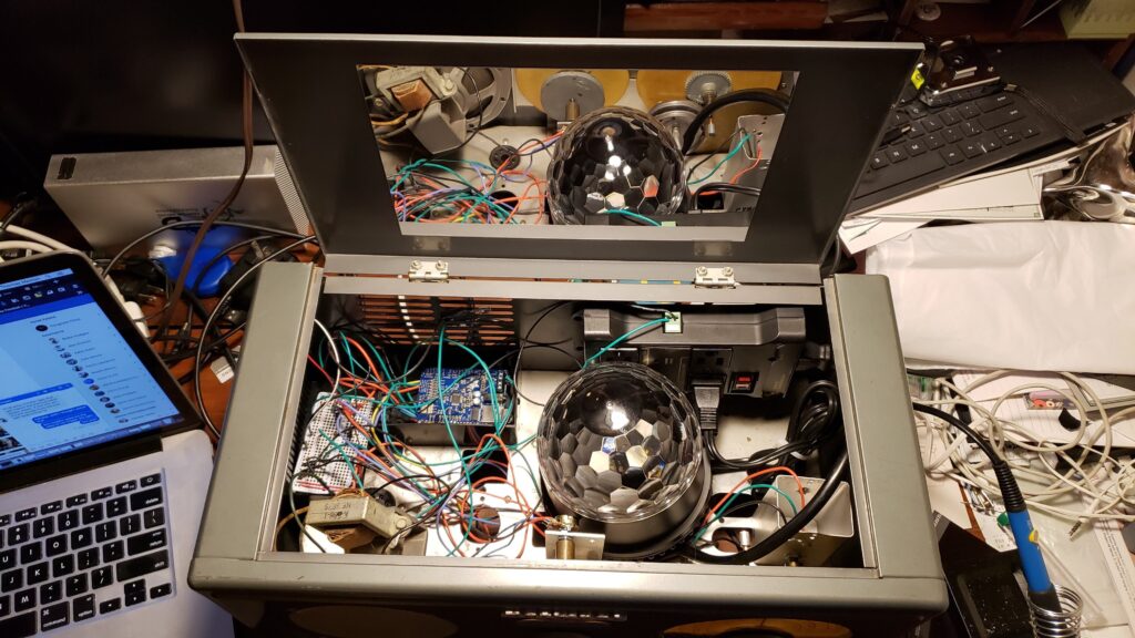
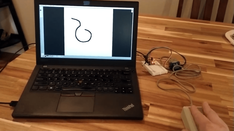
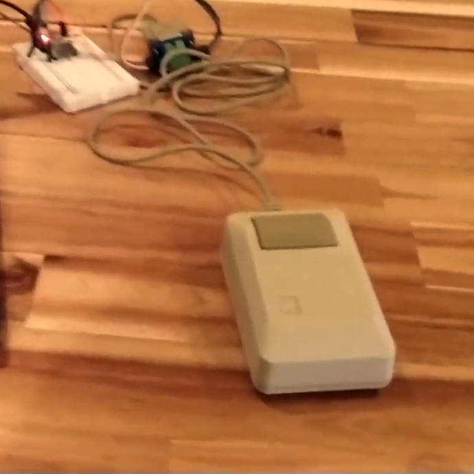
Need to hook a classic Mac mouse up to your modern machine with the help of a DIY USB adapter? [John Floren] has you covered. [John]’s solution uses a board with an ATmega32U4 microcontroller on it to connect to the Mac mouse on one end, and emulate a USB HID (Human Interface Device) on the other. A modern machine therefore recognizes it like it would any other USB input device.
Why is this necessary? The connector on the classic Mac mouse may look like a familiar DE-9 connector, but it is not an RS-232 device and wouldn’t work if it were plugged into a 9-pin serial port. The classic Mac mouse uses a different pinout, and doesn’t have much for brains on the inside. It relies on the host computer to read its encoders and button states directly.
Even if one does not particularly want to use a classic Mac mouse for daily work, there’s definitely value in this kind of thing for those who deal in vintage hardware: it allows one to function-check old peripherals without having to fire up a vintage machine.
After covering a few of his builds at this point, we think it’s abundantly clear that [Igor Afanasyev] has a keen eye for turning random pieces of antiquated hardware into something that’s equal parts functional and gorgeous. He retains the aspects of the original which give it that unmistakable vintage look, while very slickly integrating modern components and features. His work is getting awfully close to becoming some kind of new art form, but we’re certainly not complaining.
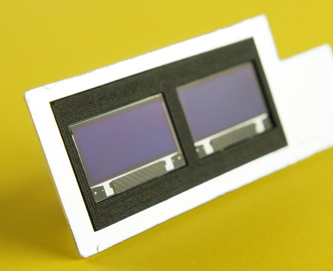
His latest creation takes an old-school “Monopak” electronic flash module and turns it into a desk clock that somehow also manages to look like a vintage television set. The OLED displays glowing behind the original flash diffuser create an awesome visual effect which really sells the whole look; as if the display is some hitherto undiscovered nixie variant.
On the technical side of things, there’s really not much to this particular build. Utilizing two extremely common SSD1306 OLED displays in a 3D printed holder along with an Arduino to drive them, the electronics are quite simple. There’s a rotary encoder on the side to set the time, though it would have been nice to see an RTC module added into the mix for better accuracy. Or perhaps even switch over to the ESP8266 so the clock could update itself from the Internet. But on this build we get the impression [Igor] was more interested in playing with the aesthetics of the final piece than fiddling with the internals, which is hard to argue with when it looks this cool.
Noticing the flash had a sort of classic TV set feel to it, [Igor] took the time to 3D print some detail pieces which really complete the look. The feet on the bottom not only hold the clock at a comfortable viewing angle, but perfectly echo the retro-futuristic look of 50s and 60s consumer electronics. He even went through the trouble of printing a little antenna to fit into the top hot shoe, complete with a metal ring salvaged from a key-chain.
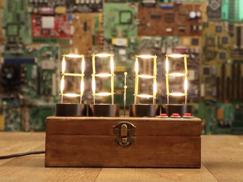
If you’ve ever wanted a vintage-style timepiece, or to test your soldering abilities, this clock by YouTuber Electronoobs will let you do both at once.
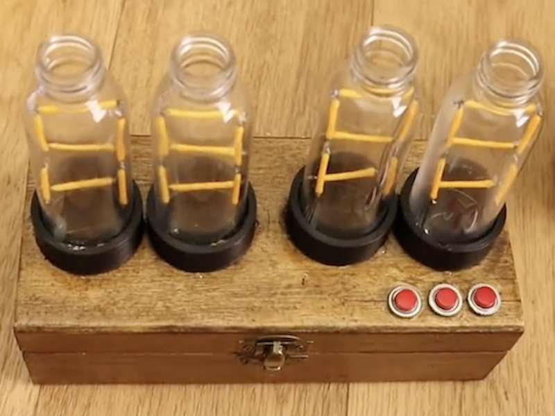
It features four display modules that resemble Nixie tubes, each made out of LED filaments soldered onto a steel wire frame. If you find soldering enjoyable and relaxing, this is likely a good project for you; though if not, there are of course other options.
The device is controlled by an Arduino Nano, along with a MAX7219 display driver to power the LEDs as needed. An RTC module keeps things “ticking” at the correct pace, and a pair of buttons on top of the wooden enclose allow the time to be adjusted as needed.
I’ve made some “Nixie” tubes. These are actually 7-segment displays made with filament LEDs but placed in a plastic bottle so it will have a more vintage nixie look. To control the LEDs I’m using the MAX7219 driver that could control 4 x 7-segment displays. To get the real time, I’m using the DS3231 module that works with an I2C communication so it’s easy to use. The project also has 2 push buttons to set the hour and minute. All is inside a wood case painted with varnish so it will look more vintage.
Check it out in the video below, or see the build write-up for more info.
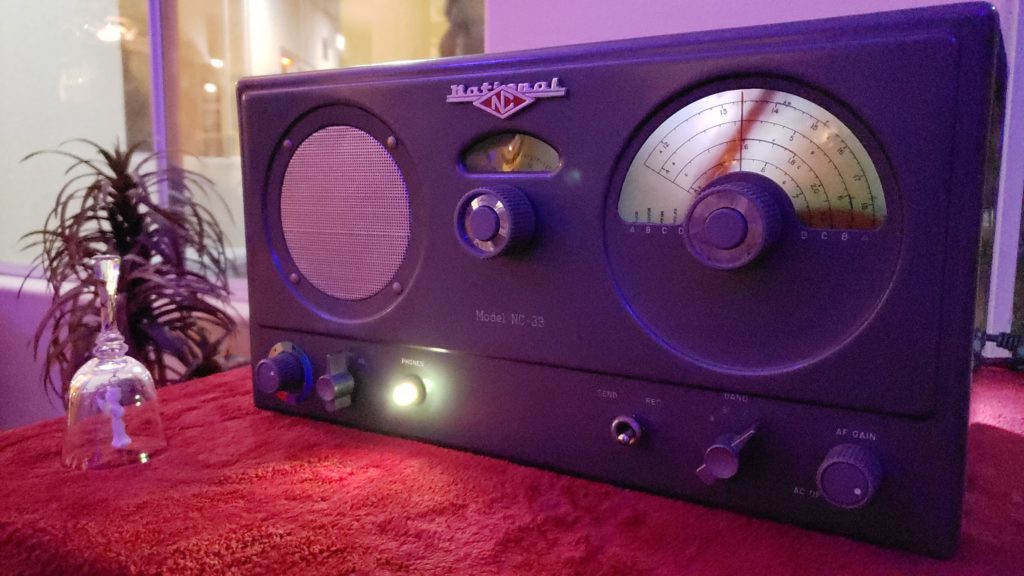
Maker Thomas Meston needed a “mysterious looking device” that allows players to enter codes obtained via an original party game. What he came up with is entitled “Dr. Hallard’s Dream Transmission Box,” and consists of an Arduino, a party light, a smoke machine, and other components stuffed into a broken National NC-33 ham radio.
This radio makes a really excellent enclosure for the electronics inside, and when the device is properly activated the winning team hears a special message via an Arduino Uno-controlled MP3 shield, accompanied by laser lights and smoke.
How it works:
When the box is switched on you hear static and see a yellow light. The device is ready for the codes to be entered.
Once all three dials have been set, the player switches the bottom toggle to “send” state, the box will message back whether team blue or team red has entered any codes with a quick flash of either a red or blue led.
If all three dials are set to red codes, the red team wins and hears a special message through the speaker just for them. The laser lights and smoke machine will be activated at the same time.
If all three dials are set to blue, a different message will play as well as activating the smoke machine and laser lights.
More info on the project can be found here, and while it might seem like a shame to modify this kind of vintage equipment, Meston notes that he sees this as giving it a nice second life since it was previously non-functional.
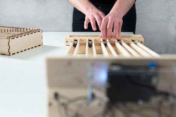
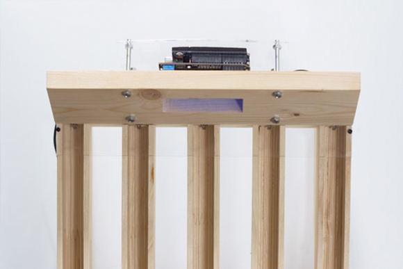
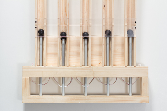
Julian Hespenheide is an interaction designer based in Germany who submitted to Arduino blogpost a writing machine called émile. It’s an interactive installation created in collaboration with Irena Kukric, David Beermann, Jasna Dimitrovskais and using Baudot code - a binary 5-bit code, predecessor of ASCII and EBCDID – intended for telecommunication and electronic devices, representing the entire alphabet.
It runs on Arduino Uno and translates the bauds (/?b??d/, unit symbol Bd) into moving objects that are being sent over physical tracks in order to illustrate a simple computational process of 5-bit binary information transmission:
The machine was built in six days with four people. In our group we came to the conclusion, that not every process in a computer is really transparent and it already starts when you type a simple letter on a keyboard. To unwrap this “black box” of data transmission, we set our goal to build a small writing machine where you can literally see bits rolling around. After some research we got back to the beginnings of Telefax machines and data transmission using Baudot-code. We then quickly designed punchcards and mapped them to a slightly altered baudot code table and cut them with a laser cutter from 5mm plywood.
Whenever a marble hits a switch, a short timer goes off and waits for input on the other switches. If no other marbles are hitting those switches, we finally translate the switches that have been hit into the corresponding letter.
Several years ago, Chris Gregg, a Tufts University lecturer and computer engineer, received a letter from his friend Erica. This wouldn’t be so unusual, except that it was typed on an actual typewriter, not a printer. Gregg is a fan of vintage typewriters, but, as with myself, makes many mistakes, […]
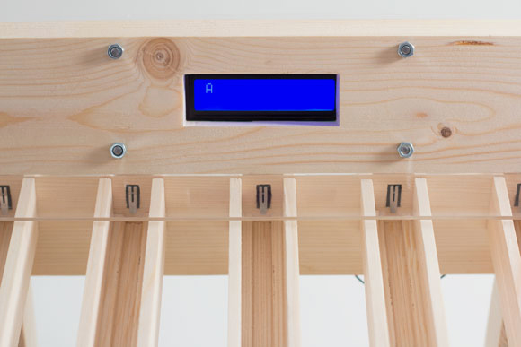
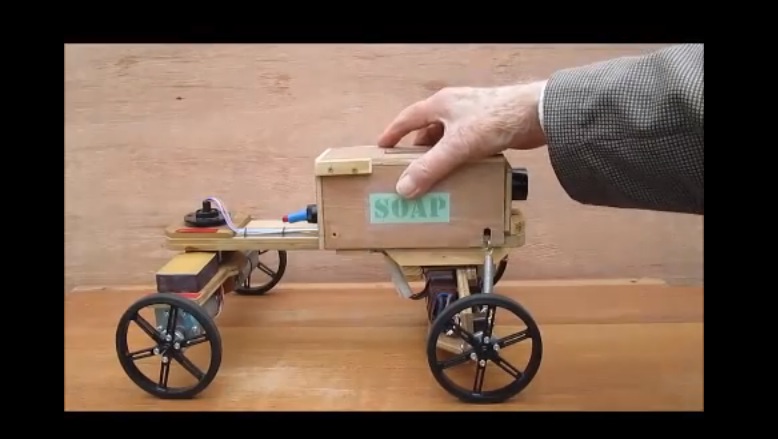
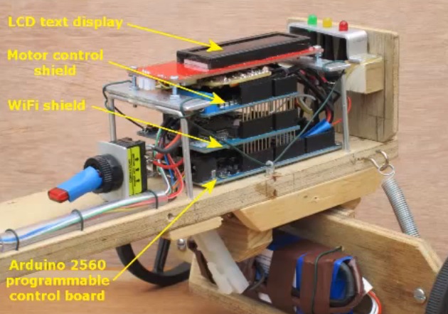
In the following 10-minute video, the Currah team is showing us all the details of Wood Lizzie, a project experimenting with Arduino Mega and Wi-Fi Shield, a very flexible steering system and the virtually unlimited control range afforded by WiFi and Internet Protocol:
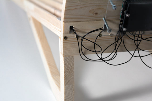
The original plan was to construct one of the two-wheeled robots very popular with hobbyists but it was eventually decided that the resulting vehicle would be of very limited application and capable only of traversing smooth surfaces. However, note that the current design can be viewed as the drive of a two-wheeled robot coupled with a trailer by means of a 360 degree pivot. A slip ring capsule within the pivot enables the heavy battery and bulky control system to be separated from the drive and located on the trailer thereby distributing weight evenly between the four wheels.
DIY soap-carts were pretty common among kids in the first part of the 20th century and built from old pram wheels, scrap wood and, typically, soap boxes. They could provide a lot of fun for the family at very low cost and in recent years there’s a new interest in them especially to those appreciating their vintage look!
It’s no secret that I enjoy kit reviews – it’s always interesting to see how well a kit goes together, along with the quality of parts, documentation and so on. But what about kits from the past? And not 2003. Recently a very rare opportunity to purchase a sealed Sinclair Radionics Cambridge calculator kit appeared on ebay – so it was ordered rapidly and duly delivered to the office. And thus the subject of this review.
You may be familiar with the Sinclair name – Sir Clive Sinclair introduced many innovative and interesting products to the UK and world markets in his own style. Some were a raging success, such as the ZX-series home computers – and some were not. However in 1973 Sinclair introduced a range of calculators, starting with the “Cambridge”. It’s a simple four-function calculator with an LED numeric display and a somewhat dodgy reputation.
The design evolved rapidly and at the Mark III stage it was sold assembled and as a kit. At the time handheld calculators were quite expensive, so the opportunity to save money and get one in kit form would have been quite appealing to the enthusiast – in January 1974 the kit retailed in the UK for 24.95 (+ VAT):
Assembly
Putting the Cambridge together required a balance of healthy paranoia, patience and woodworker mentality (measure twice – cut once). There wouldn’t be any second chances, or quick runs down to Altronics for a replacement part (well … there was one) so care needed to be taken. If you’re curious about the details, I’ve uploaded 82 full-resolution images from the build, including both instruction manuals and schematic onto flickr. Now to get started.
The kit arrives in a neat, retail-orientated package:
… with the components on one side of the foam:
… and the other side held he assembly guide (underneath which was a very short length of solder and the carrying case):
At this point I was starting to have doubts, and thought it would be better off in storage. But what fun would that be? So out with the knife and the shrink-wrap was gone, revealing the smell of 1974 electronics. Next to whip out the instructions and get started:
They are incredibly detailed, and allow for two variations of enclosure and also offer tips on good construction – as well as the schematic, BOM and so on. Like any kit it’s wise to take stock of the components, which gave us the PCB:
… the passives, diodes and transistor – and some solder wick:
At this point it turned out the all but one of the resistors were anywhere near the specified values in the instructions, and I wasn’t going to trust those electrolytic capacitors after 39 years. The replacement parts were in stock – including the original 1n914 diode that was missing from the kit. Thanks Clive. There was also a coil of unknown value:
… and the ICs, which included the brains of the operation – a General Instrument Microelectronics CZL-550:
… and an ITT 7105N:
… a bag of battery clips, buttons and adhesive-backed foam (which deteriorated nicely):
At this point it was time to fire up the Hakko and start soldering, not before giving the PCB a good hit with the Servisol cleaner spray. I was worried about the tracks lifting while soldering due to heat and old-age, however the PCB held up quite well. The first step is to solder in the clips that hold (just) four AAA cells:
… then the resistors and diodes:
… followed by the transistor, ITT IC, ceramic capacitor and coil:
Uh-oh – that ceramic went in the wrong hole. One leg was soldered where the coil was to sit. Without wanting to damage the PCB, de-soldering it was a slow, slow process. Then of course I didn’t have a ) 3.3nF in stock, so a quick spin to Altronics solved that problem (I bought 50) – one of which finally went in:
The transistor was also a bit of a puzzle, I hadn’t seen that enclosure type and the manual wasn’t much help, so the semiconductor analyser tester solved that problem:
The next step was to fit the display, which is wedged in the large gap at the top of the PCB. The tracks on the PCB are supposed to meet the display, however time had affected the tracks on the display module, so I soldered small wire links across the gaps:
Following the display were the two (new) electrolytics:
And now to the main IC. There wasn’t any second chances with this, and after some very gently pin-bending it dropped in nicely:
After a short break it was time to assemble the keypad, which went smoothly. After cleaning all the foam dust off the buttons, they dropped in to their frame which in turn dropped into the enclosure, followed by the keypad layers:
You can also see in the display window and shroud have been fitted. From here the PCB is inserted:
… and a sticker from years gone by, as well as the metal clip over the bottom of the power switch. At this point a quick test with four AAA cells showed signs of life on the display, so the rear enclosure could be fitted:
Now for the battery and final cover, and it’s ready to go!
The digits are quite sharp, but very small – and set back from the window. This makes photography quite difficult. At the time if your calculator didn’t work, you could send it off to Sinclair and they’d repair or possibly replace it for you:
Using the Cambridge
Well it works, so you have a calculator which is genuinely useful. However the Cambridge has a few quirks, which are attributed to the basic functions of the main IC. For example, when entering numbers the screen is filled with leading zeros until you select a function, however by using the manual you can complete complex work including square roots, percentages, loan repayments and much more.
Furthermore the Cambridge is quite the silent achiever, you can work with numbers as small as 1x10E-20 and up to 9.9999999E79. You simply enter the numbers in decimal form (e.g. 0.000000000123) … even though the display won’t show all the digits, they’re being stored in a register. To then extract the result, you continually multiply or divide by ten (making note of how many times you do that) until the digits appear on the screen. It sounds nuts today – but in 1974 it would have been a cheap way of avoiding a more expensive calculator. In the following video you can see th Cambridge in action, plus the results of dividing by zero:
More about Sinclair
The following video is a BBC dramatisation of the rise of the home computer in the UK market, and the competition between Sir Clive Sinclair (Sinclair) and Adam Curry (Acorn Computers) – which is quite entertaining:
You can find out more about the history of Sir Clive Sinclair here, and the calculator range here. If anyone can connect us with a Science of Cambridge MK14 computer, contact us.
Conclusion
From a 1974 perspective, that would have been a great kit to make, with some love and care it would have been successful. By today’s standards it was quite average – however you can’t really judge it from a 2013 perspective. Nevertheless, kudos to Sir Clive Sinclair for his efforts in knocking out a useful product as a kit. If you’re a collector, and see a sealed unit on ebay or elsewhere, give it a whirl. Just take your time, “think before doing”, and replace as many of the components as possible. I’ve put all the images in full resolution up on flickr, so you can follow along in more detail.
And while you’re here – are you interested in Arduino? Check out my new book “Arduino Workshop” from No Starch Press.
In the meanwhile have fun and keep checking into tronixstuff.com. Why not follow things on twitter, Google+, subscribe for email updates or RSS using the links on the right-hand column? And join our friendly Google Group – dedicated to the projects and related items on this website. Sign up – it’s free, helpful to each other – and we can all learn something.
Planet Arduino is, or at the moment is wishing to become, an aggregation of public weblogs from around the world written by people who develop, play, think on Arduino platform and his son. The opinions expressed in those weblogs and hence this aggregation are those of the original authors. Entries on this page are owned by their authors. We do not edit, endorse or vouch for the contents of individual posts. For more information about Arduino please visit www.arduino.cc
You are currently browsing the archives for the vintage category.

 Why is this necessary? The connector on the classic Mac mouse may look like a familiar DE-9 connector, but it is not an RS-232 device and wouldn’t work if it were plugged into a 9-pin serial port. The classic Mac mouse uses a different pinout, and doesn’t have much for brains on the inside. It relies on the host computer to read its encoders and button states directly.