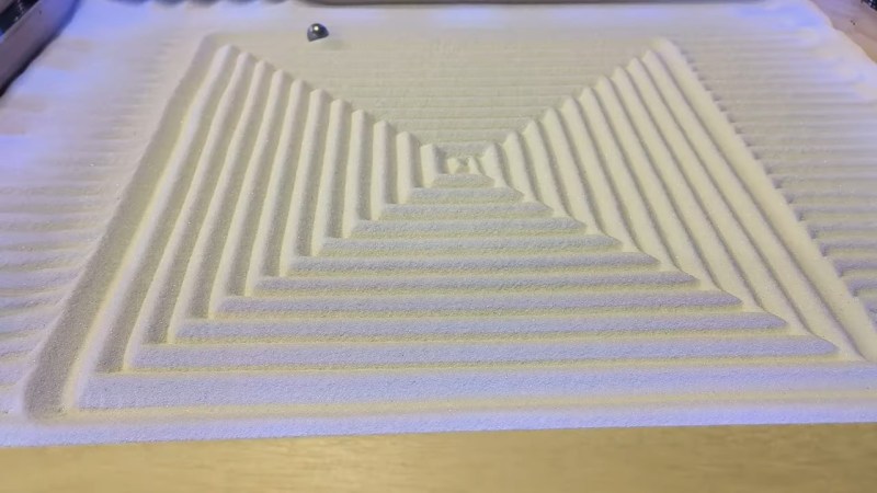
There’s nothing fun about a Sisyphean task unless you’re watching one being carried out by someone or something else. In that case, it can be mesmerizing like this Arduino-driven kinetic sand table.
What you can’t see. Image via [thang010146] on YouTubeLike many of these builds, it all started with an ordinary coffee table from the hacker’s favorite furnitüre store. [NewsonsElectronics] opened it up and added a 3mm-thick board to hold the sand and another to hold the rails and magnets.
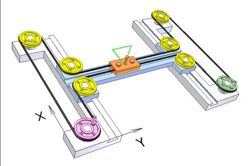
After designing some pieces to connect the rails and pulleys together, [NewsonsElectronics] let the laser cutter loose on some more 3mm stock. A pair of stepper motors connected to a CNC shield do all of the work, driving around a stack of magnets that causes the ball bearing to trudge beautifully through the sand.
Be sure to check out the videos after the break. The first is a nice demonstration, and the second is the actual build video. In the third video, [NewsonsElectronics] explains how they could write the world’s smallest GRBL code to swing this with a single Arduino. Hint: it involves removing unnecessary data from the g-code generated by Sandify.
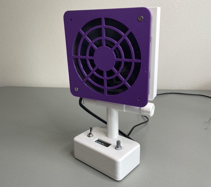
If you solder (and we know you do), you absolutely need ventilation, even for that lead-free stuff. Fortunately, [tinyboatproductions] has gotten into air quality lately and is here to help you with their snappy 3D printed air-filtering design.
At the heart of this build is a 120 mm notoriously-quiet Noctua fan coupled with a carbon filter. It does what you’d think — position the fan the right way and it sucks the air through the filter, which catches all those nasty particles.
The only problem is that the Noctua uses PWM, so there’s no governing it with a just potentiometer. To get around this, [tinyboatproductions] introduced an Arduino Nano and a buck converter, both of which were admittedly a bit overkill. Now the speed can be controlled with a pot.
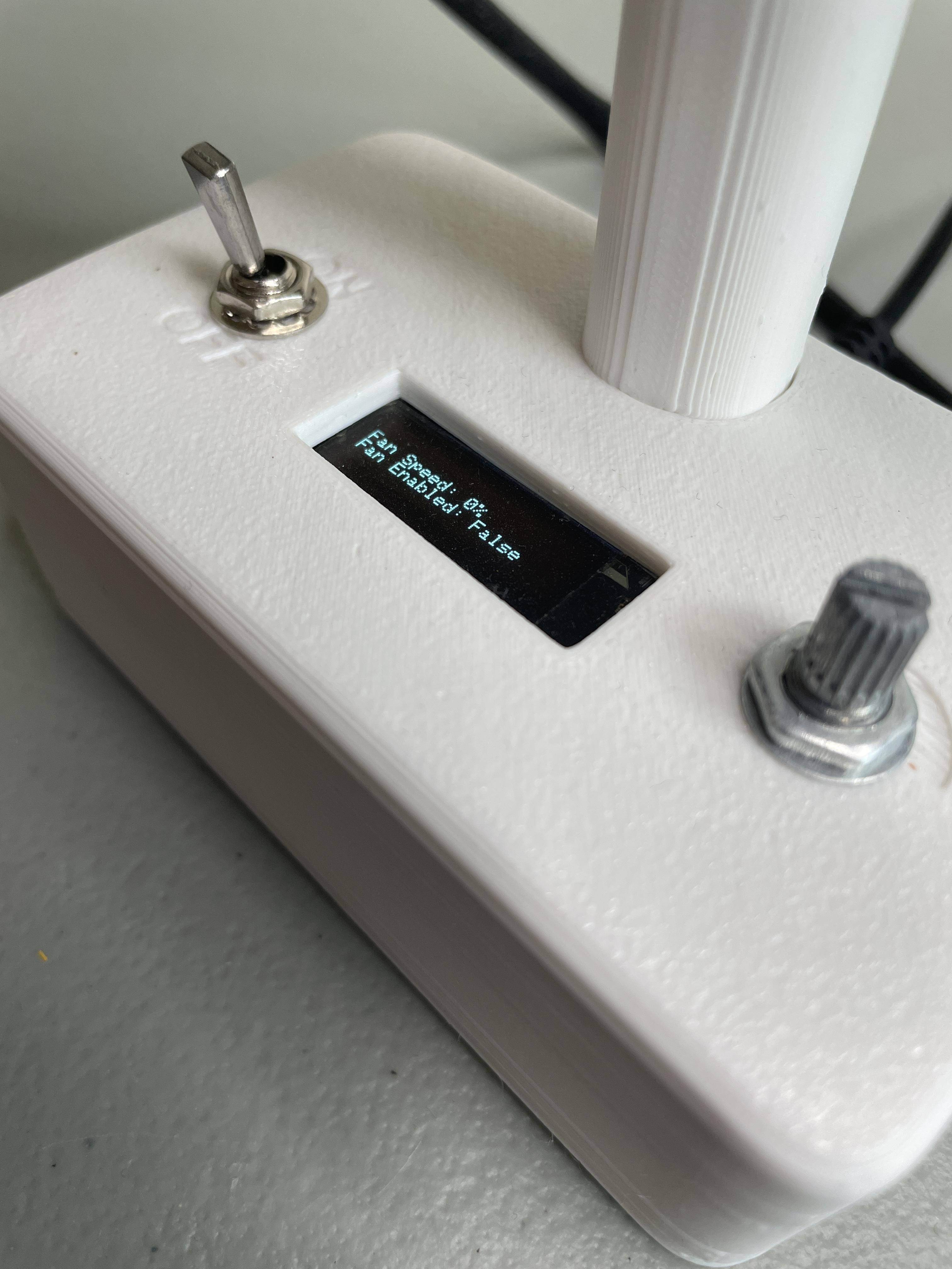
Once control of the fan was sorted, [tinyboatproductions] decide to add an OLED display to show the fan speed and power condition, which is a nice touch. Be sure to check out the build video after the break.
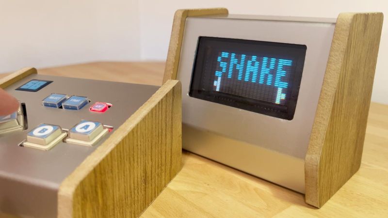
Small in size, low-resolution, blocky segments, and a limited color palette — all characteristics of the typical vacuum fluorescent display, any of which would seem to disqualify them as the display of choice for a lot of applications. But this is Hackaday, and we don’t really pay much attention to what we’re supposed to do, but rather to what’s fun and cool to do. So when we see something like a VFD game console, we just have to sit up and take notice.
In a lot of ways, the design of [Simon Boak]’s Arduino-based VFD console is driven by his choice of display. The Noritake Itron GU20X8-301 VFD is a “tricolor” display with eight rows of 20 rectangular pixels. Each pixel is composed of six short linear segments, with alternating red and blue colors. Turning on either set of segments yields one of the two base colors, while turning on both yields a sorta-kinda whitish color, if you squint a bit.
[Simon] chose a two-piece design for his console, with a separate controller and display. The controller holds the Arduino Nano and all the controls, plus a piezo buzzer for fun. The display case connects to the controller with a ribbon cable and holds the VFD power supply and driver. To celebrate the retro look of the VFD, both cases are decked out with woodgrain side panels. [Simon] chose appropriately blocky games for the console, like Snake, Conway’s Game of Life, and the venerable snow demo. We’d imagine Pong would be a good choice too, as well as perhaps Tetris if the display were flipped on its side.
We really like the look of this console, and we appreciate putting an otherwise obsolete display to use in a creative way. If you want to learn a little more about these displays, check out this love letter to the VFD.
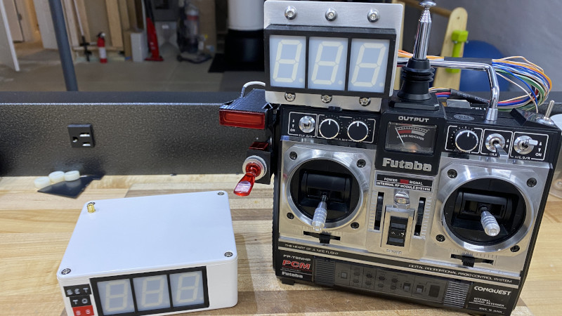
Obviously, the most iconic piece of fictional hardware from the Back to the Future films is Doc Brown’s DeLorean DMC-12 time machine. But we’d have to agree with [Jason Altice] of CodeMakesItGo that the second-most memorable gadget is the modified Futaba remote control used to control the DeLorean from a distance. Now, thanks to his detailed build guide, you can build your own version of the time machine’s controller — complete with working speed readout.
Now to be clear, [Jason] isn’t claiming that his build is particularly screen accurate. It turns out that the actual transmitter used for the prop in the film, the Futaba PCM FP-T8SGA-P, has become difficult to find and expensive. But he argues that to the casual observer, most vintage Futaba transmitters are a close enough match visually. The more important part is recreating the extra gear Doc Brown bolted onto his version.
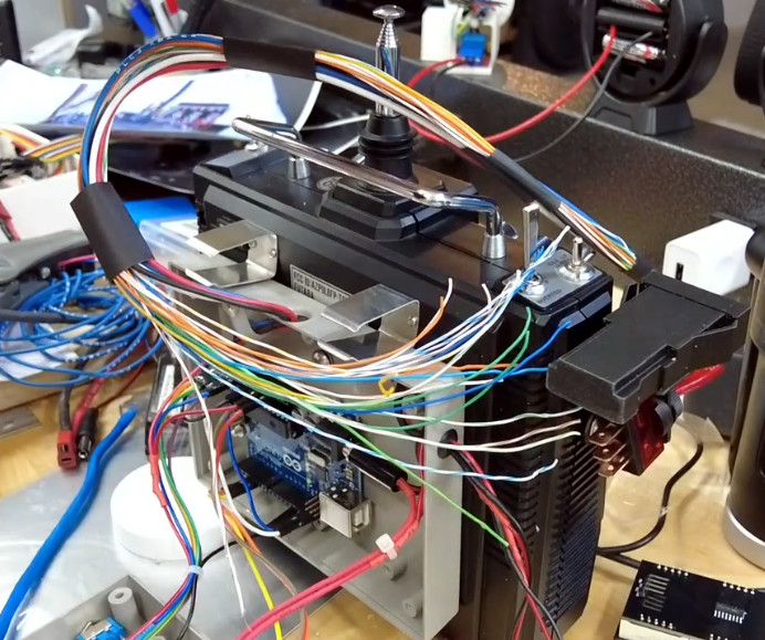
All but four of the display wires are fake.
To that end, [Jason] was able to source some screen accurate hardware to kit out his transmitter, such as the Unibox 140 project box and the metal 9 V battery clips. Other components, like the lighted Molex 1820 switch, were harder to track down. Luckily we live in the age of cheap desktop 3D printers, and he was able to run off an impressively accurate replica without too much trouble.
Of course, the stand out feature is the seven-segment LED speed indicator. Each digit is a separate 25 mm (1 inch) SC10-21SRWA display, which have been mounted together on a custom PCB along with a TM1650 controller. An Arduino Uno inside the Unibox 140 drives the display, and receives speed data from the transmitter in the car using a long-range Reyax LoRa RYLR998 module.
[Jason] built the GPS-equipped “speed box” to closely resemble the movie version, albeit with three functional digits compared to only two in the original prop. Internally it’s using the same LED display, LoRa module, and Arduino Uno as the transmitter. We liked the approach of keeping the hardware more or less the same on both sides of the link, keeps things nice and simple.
Now you certainly don’t need a DeLorean time machine to test out your finished remote control, but we appreciate that [Jason] went through the trouble of renting one so he could show off his creation in style. The final product looks great, and ranks right up there with the replica time circuits on the list of BttF props we’d love to have up on the shelf.
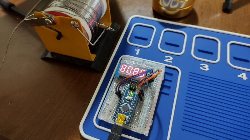
Are you a math aficionado in need of a new desk toy? Then do we have the project for you. With nothing more than an Arduino and a seven-segment LED module, [Cristiano Monteiro] has put together a little gadget that will slowly work its way through the digits of Pi forever…or until you get bored of looking at it and decide to use the parts for something else.
On the hardware side, we really can’t overstate how simple this project is. A common four-digit LED display is connected up to an Arduino Nano, which is then plugged into the computer for power. [Cristiano] is using a breadboard here, but you could just as easily use four female-to-female jumpers to connect the two devices together. We suppose this would be a pretty good project for anyone who’s looking to get some practical experience with PCB design as well.
The real magic is in the software, which [Cristiano] has been kind enough to release under the MIT license. Calculating Pi on such a resource-constrained chip as the ATmega328P is far from ideal, but by porting over a C++ algorithm developed by [Xavier Gourdon] and [Pascal Sebah] for their paper Computation of the n-th Decimal Digit of π with Low Memory he was able to pull it off, albeit slowly.
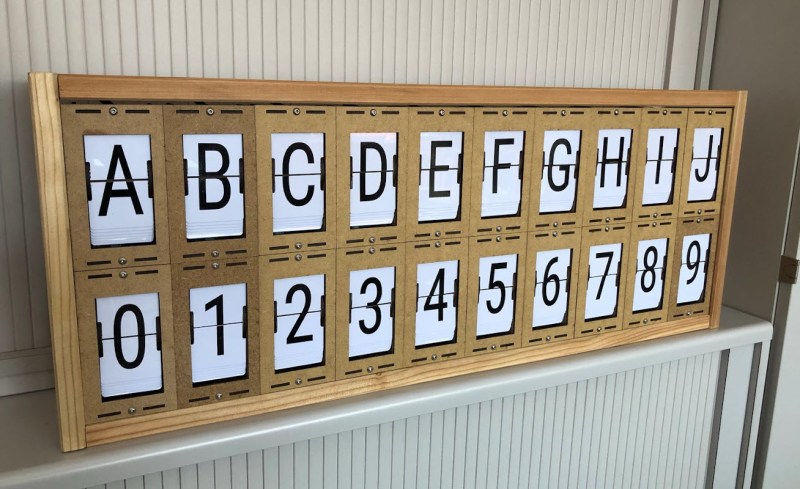
LED and LCD displays are a technological marvel. They’ve brought the price of televisions and monitors down to unheard-of levels since the days of CRTs, but this upside arguably comes with an aesthetic cost. When everything is covered in bland computer screens, the world tends to look a lot more monotonous. Not so several decades ago when there were many sharply contrasting ways of displaying information. One example of this different time comes to us by way of this split-flap display that [Erich] has been recreating.
Split-flap displays work by printing letters or numbers on a series of flaps that are attached to a spindle with a stepper motor. Each step of the motor turns the display by one character. They can be noisy and do require a large amount of maintenance compared to modern displays, but have some advantages as well. [Erich]’s version is built out of new acrylic and MDF, and uses an Arduino as the control board. A 3D printer and CNC machine keep the tolerances tight enough for the display to work smoothly and also enable him to expand the display as needed since each character display is fairly modular.
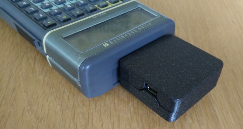
Introduced in 1984, the Psion Organiser series defined the first generation of electronic organizers or PDAs (personal digital assistants). Even though these devices are now over 30 years old, the Psion Organiser scene is alive and well: with new hardware and software is still being developed by enthusiasts the world over.
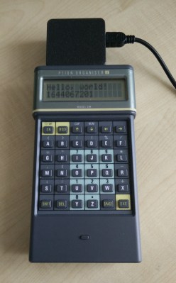
The Organiser II, with its brand-new USB interface
One of those enthusiasts is [James Stanley], who designed and built a USB interface for the Psion Organiser II. Although a “CommsLink” module providing an RS-232 port was available back in the day, it’s become hard to find, inspiring [James] to design a completely new module based on an Arduino Nano. Hooking it up to the Psion’s data bus was a simple matter of wiring up the eight data lines to the Nano’s GPIO ports. A set of series resistors served to prevent bus contention without having to add glue logic.
Getting the software working was a bit more difficult: the Organiser’s native OPL programming language doesn’t allow the user to directly access the expansion port’s memory address, so [James] had to write a routine in HD6303 machine code to perform the read, then call that routine from OPL to display the result on the screen. Currently, the routine only supports reading data from the Arduino, but extending it to a bidirectional interface should be possible too.
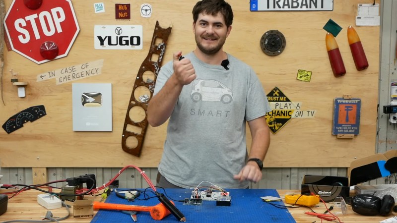
Raise you’re hand if you’ve ever soldered directly to a battery even though you know better. We’ve all been there. Sometimes we get away with it when we have a small pack and don’t care about longevity. But when [Robert Dunn] needed to build a battery pack out of about 120 Lithium Ion cells, he knew that he had to do it The Right Way and use a battery spot welder. Of course, buying one is too simple for a hacker like [Robert]. And so it was that he decided to Build a Spot Welder from an old Microwave Oven and way too much mahogany, which you can view below the break.
Spot Welding leaves two familiar divots in the attached tab, which can be soldered or welded as need.
For the unfamiliar, a battery spot welder is the magical device that attaches tabs to rechargeable batteries. You’ll notice that all battery packs with cylindrical cells have a tab with two small dimples. These dimples are where high amperage electricity quickly heats the battery terminal and the tab until they’re red hot, welding them together. The operation is done and over in less than a second, well before any heat damage can be done. The tab can then be soldered to or spot welded to another cell.
One of the most critical parts of spot welding batteries is timing. While [Robert Dunn] admits that a 555 timer or even just a manual switch and relay could have done the job, he opted for an Arduino Uno with a 4 character 7 segment LED display that shows the welding time in milliseconds. A 3d printed trigger and welder handle wrap up the hardware nicely.
The build is topped off by a custom mahogany enclosure that is quite a bit overdone. But if one has the wood, the time, the tools and skills (and a YouTube channel perhaps?) there’s no reason not to put in the extra effort! [Robert]’s resulting build is almost too nice, but it’ll certainly get the job done.
Of course, spot welders are almost standard fare here at Hackaday, and we’ve covered The Good, The Bad, and The Solar. Do you have a battery welder project that deserves a spot in Hackaday’s rotation? By all means, send it over to the Tip Line!
It’s always good to see old hardware saved from the junk pile, especially when the end result is as impressive as this analog gauge weather display put together by [Build Comics]. It ended up being a truly multidisciplinary project, combing not only restoration work and modern microcontroller trickery, but a dash of woodworking for good measure.
Naturally, the gauges themselves are the real stars of the show. They started out with rusted internals and broken glass, but parts from a sacrificial donor and some TLC from [Build Comics] got them back in working order. We especially like the effort that was put into making the scale markings look authentic, with scans of the originals modified in GIMP to indicate temperature and humidity while retaining the period appropriate details.
To drive the 1940s era indicators, [Build Comics] is using an Arduino Nano and a DHT22 sensor that can detect temperature and humidity. A couple of trimmer pots are included for fine tuning the gauges, and everything is mounted to a small scrap of perfboard hidden inside of the custom-made pine enclosure.
Despite all the incredible advancements made in video game technology over the last few decades, the 8-bit classics never seem to go out of style. Even if you weren’t old enough to experience these games when they were new, it’s impossible not to be impressed by what the early video game pioneers were able to do with such meager hardware. They’re a reminder of what can be accomplished with dedication and technical mastery.
The grid has been split up for easier printing.
If you’d like to put a little retro inspiration on your desk, take a look at this fantastic 16 x 16 LED matrix put together by [Josh Gerdes]. While it’s obviously not the only thing you could use it for, the display certainly seems particularly adept at showing old school video game sprites in all their pixelated glory. There’s something about the internal 3D printed grid that gives the sprites a three dimensional look, while the diffused glow reminds us of nights spent hunched over a flickering CRT.
The best part might be how easy it is to put one of these together for yourself. You’ve probably got most of what you need in the parts bin; essentially it’s just a WS2812B strip long enough to liberate 256 LEDs from and a microcontroller to drive them. [Josh] used an Arduino Nano, but anything compatible with the FastLED library would be a drop-in replacement. You’ll also need a 3D printer to run off the grid, and something to put the whole thing into. The 12×12 shadowbox used here looks great, but we imagine clever folks such as yourselves could make do with whatever might be laying around if you can’t nip off to the arts and crafts store right now.
Planet Arduino is, or at the moment is wishing to become, an aggregation of public weblogs from around the world written by people who develop, play, think on Arduino platform and his son. The opinions expressed in those weblogs and hence this aggregation are those of the original authors. Entries on this page are owned by their authors. We do not edit, endorse or vouch for the contents of individual posts. For more information about Arduino please visit www.arduino.cc
You are currently browsing the archives for the classic hacks category.