Posts | Comments

Planet Arduino

Archive for the ‘history’ Category

History of the Arduino UNO

As familiar as we all are with the UNO, there’s probably a lot you don’t know about the iconic Arduino microcontroller board. Put on your rose-tinted spectacles, and let’s wax poetic about the origins of this beloved maker board.

Rise of the Techno-Hippies

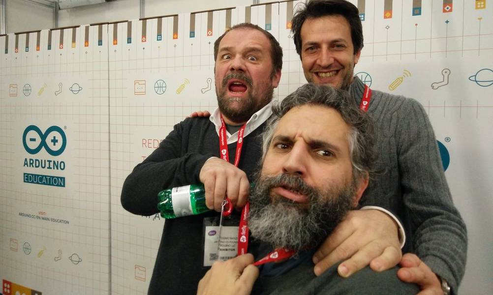
By 2009, the team that would become Arduino was gathering steam. A team that Make: Magazine once referred to as “designers, teachers, artists, and techno-hippies.”

I don’t think anyone on that team would object to such a definition.

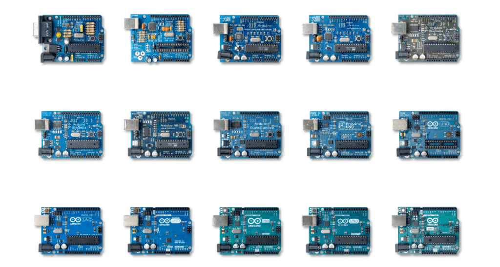
Forged in the crucible of a classroom, the idea of an accessible, affordable electronics development platform was under serious investigation. It would eventually give birth to the Arduino UNO, but despite its name meaning “one,” this is far from Arduino’s first board. Moreover, its name was chosen to mark a point in Arduino’s story where the business itself came out of beta and into version 1.0.

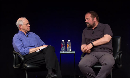
“The UNO is an arrival point of a large number of small experimentations and incremental improvements,” says co-founder Massimo Banzi.

These experiments weren’t just a learning experience for electronics design. They were useability tests, and even marketplace research. Each little quirk, unexpectedly popular feature and, of course, mistake helped to define what makers wanted and needed.

This was a time when the maker movement was still unrepresented by a defining brand or killer product. But not for long.

Massimo and David with Arduino CEO, Fabio Violante

Driving Towards the Future

The journey to the UNO wasn’t short, but it did have a distinct destination. The notion of an enhanced user experience was very prominent, although the people who would become the founders of Arduino hadn’t necessarily articulated it even to themselves. Looking back, it’s easy to see that this guiding principle was there from the beginning.

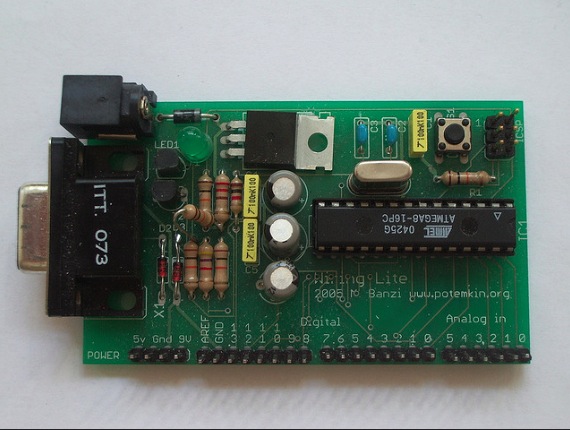
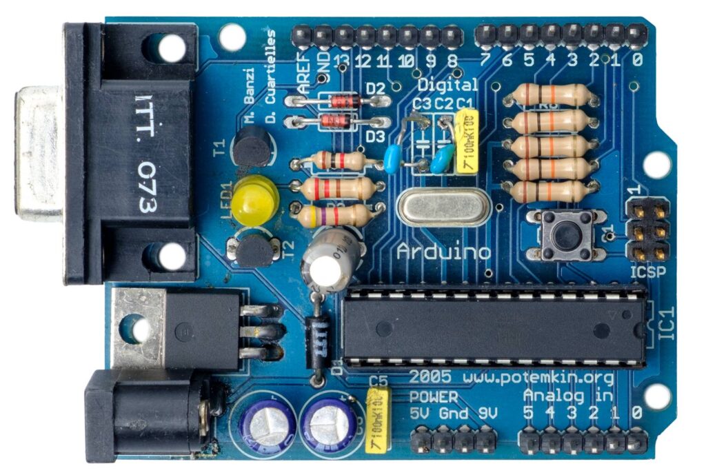
“On the original Arduino serial board, look at the components,” says co-founder David Cuartielles, talking about the earliest of Arduino’s self-assembly boards, which were used almost exclusively in the classroom. “They’re sorted by value. I made sure that components of a similar type and value were together, to minimize mistakes during assembly. For example, there were two diodes. In terms of operation, they’re working in opposite directions to each other. But to reduce errors when populating the board by hand, I set the diodes facing in the same direction, and the PCB’s tracks take care of orientation. So it’s optimized for education, not for electronic operation!”

“Back in the day we used to use FTDI chips,” Massimo recalls. “A Scottish company, now in Singapore. Great chips, but you had to install drivers to get your computer to recognize devices when you plugged them in.”

“Which is when we realized there was this thing called CDC (communications device class) protocol, which was embedded into operating systems. It’s the reason you don’t need a driver for a USB serial port. We found that you could develop a firmware for some simple Atmel processors that worked just the same as FTDI chips, but would liberate us from needing a driver.”

This opened the door to reprogramming the firmware and making the boards do other things. Some people created MIDI firmware to send notes to a computer. Others made HID firmware so they could emulate computer peripherals. It was the herald of dual processor experimentation, which piqued the interest of both Arduino users and its designers.

Press On with the UNO

These proto-UNOs also required you to press a reset button before uploading new code. It was a pretty standard requirement for any prototyping platform at the time. Most designers had simply never questioned this apparent necessity. But when the Arduino team found themselves placing more and more emphasis on user experience, this small requirement was identified as an obstacle to useability. 

It was at a workshop in Germany when Massimo figured out an alternative.

“It turned out that if you put a capacitor between the reset pin of the microcontroller and one of the serial port pins,” he explains, “it would reset the board automatically whenever you opened the port.” This small tweak became a vital and very popular aspect of the UNO’s useability.

But there were a lot of other factors that went into making the UNO so recognizable that it’s become indistinguishable from the overall Arduino brand.

The Power of One

Early Arduino boards required a more active participation when it came to powering them up.

They already offered flexibility in choosing your power source. But if you wanted to power the board from the USB or the external power jack, you had to move a jumper. Not a lot to ask, but as many of the design experiments proved, these seemingly insignificant requirements had a disproportionate effect on usability.

People would forget to set the jumper in the first place. Or have it in the wrong position when trying to power on, and frustrations ensued. So a small circuit was implemented that detected where the power was coming from, and switched to it automatically. Simple, but essential.

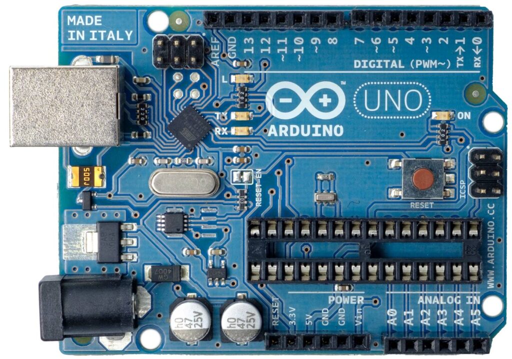
Tweaks to the power options didn’t stop there. On other boards there had been some experimentation with microUSB ports, not realizing how fragile they can be. So when it came to the UNO, the USB connector was carefully chosen for its reliability. “It’s like a Russian tank,” Massimo laughs. “It’s indestructible.”

Feeling Blue

“Going from the original design we had on a rectangular green board, to the shaped blue board that everyone recognizes now, took two days,” David recalls, musing on how Arduino could move so fast because of its focus on simplicity. “And in between we went to a party. Because the designs are very simple.”

 “The original board, before it became the Arduino UNO, was a typical green PCB,” Massimo explains, lavishing mediocrity on the state of pre-Arduino prototyping platforms. “Not so exciting. The PCB manufacturer we were talking to went on and on about how he was making blue PCBs because they were apparently easier on the eye for production line workers. We thought, ‘Hey! Blue is better, because everyone else is using green!’”

You can see a pattern in the way Arduino was beginning to question the norms of its industry. Those shades of blue and teal have become synonymous with Arduino devices, and that didn’t happen by accident. At the time, PCBs were green. Maybe beige, if they were still bare fibreglass. 

But no longer, once the UNO arrived.

Arduino didn’t just have its eye fixed on usability. It was also searching for an identity that makers would associate with enhanced experience and quality. It just so happened that the UNO was destined to become the vessel that gave that identity a tangible shape.

The beautiful blue board, with the first appearance of the brand new Arduino logo

Taking Shape

“I was teaching and I had to draw PCBs on a white board all the time,” recalls David. “And all boards were square or rectangular. So how do you tell people which is left and which is right? In order to avoid errors in plugging things in and building the boards, which originally were self-assembly, I thought it needed to be a non-symmetrical shape. Then the students could see that this is left and this is right. It wasn’t a creative decision, so much as a functional one for education purposes.”

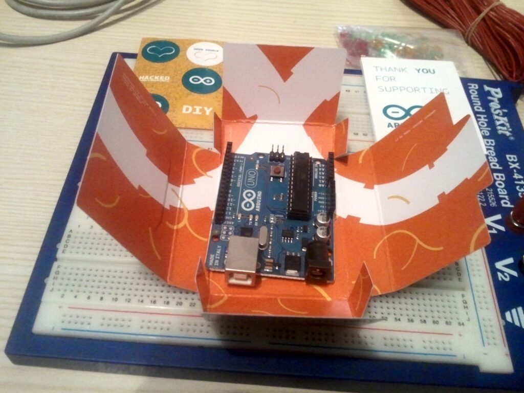
Around that same time, the school where he was teaching in Ivrea was issuing everyone with business cards. They arrived on Massimo’s desk in a small plastic box. “So that seemed like a good starting place for sizing,” Massimo remembers, “as it seemed like a great idea if we could fit the UNO in a plastic box like the one my business cards came in.”

It was taking shape as a very recognizable product. And you want to put your name on  products you’re proud of. Typically any branding on a PCB was added using the standard font that came with the Eagle PCB design software. Essentially vector lines, not graphics. This change was enacted by a former student of the Ivrea classroom, Giorgio Olivero. He was entrusted with the new Arduino identity.

“The strength of our current image depends entirely on the outstanding work Giorgio’s done,” David notes. “Giorgio understands not only graphic design, but the importance of designing the whole user experience. He understood interaction design really well. He understood the nature of the Arduino project intimately, and the needs of the end user.”

An UNO in its original packaging, designed by Giorgio Olivero. Photo courtesy of Francesco Balducci.

The UNO was the moment when quality came home in every respect. The boards were given an appealing new color, precision engineering, high quality manufacturing, and an emblem that made sure you knew you were holding an Arduino.

“The response was fantastic,” David continues, reflecting on the reception that the new Arduino and its flagship device received. “Nowadays it’s really common to do these kinds of things, but back then on the maker scene it was really unusual to put so much into making things look good, and putting a focus on the user experience.”

One Small Mistake

“When I was designing the board I made a mistake that we still have to live with,” admits Massimo. “I moved the connectors in the top right of the board half a step to the left, so the gap between the connectors is non-standard. It’s 1.27mm out. Which is fine on the connectors at the bottom, but that’s why you struggle to use a veroboard to develop shields, because the connectors aren’t quite aligned as they were meant to be.” 

It’s a mistake that had a silver lining, though. That slight misalignment also (inadvertently, perhaps) gave us a key for attaching shields the right way around. So, just between you and me, let’s pretend it was deliberate and say no more about it.

Even the first batch of UNOs that came off the production line weren’t quite where Arduino wanted them to be, quality wise. The process for milling the PCBs into the iconic UNO shape wasn’t as reliable as it is now.

A small number of the boards had rough edges where they were snapped out of the sheet after cutting. Nothing that affected the operation of the board, but not so good when your focus is on achieving a distinctive level of quality.

“A friend and I spent the weekend at the PCB manufacturers,” Massimo remembers, semi-fondly, “sandpapering the edges of the first batch of UNO boards. What else could we do?”

Ten Thousand and UNO

Makers responded very positively to the ethos behind the UNO. And that enthusiasm was directly reflected in the number of Arduino boards sold.

“I remember an article in a magazine celebrating that Arduino had sold 10,000 boards,” Massimo recalls. “Arduino was here to stay, they said, because back then if anyone sold 10,000 boards you were boss!” 

Arduino itself celebrated this milestone back in 2007, with a predecessor to the UNO called the Arduino Diecimila, meaning “ten thousand”. Interestingly enough, this was also the board that introduced automatic software resets when uploading a sketch, so you no longer had to press a reset button. Without the Diecimila, the UNO couldn’t have been born.

The Arduino Diecimila

Now Arduino’s selling in the region of 10,000 boards a week. As you can imagine, magazines and blogs have stopped writing about every maker device that hits the 10,000 milestone now. The UNO itself, in fact, has recently crossed the 10 million mark.

The Day of the UNO

It wasn’t just the Arduino UNO that was unveiled at the Maker Faire New York in 2010. It was the new Arduino. Colors, branding, logos and a refined focus on usability and recognizable quality across everything Arduino did, from the UNO to the website and the packaging. 

“I was the only one not present at that event in New York,” David laughs. “I was in a hotel in my home town of Malmö, because I had to launch the new website. At the time we were running the whole Arduino server in a $5-per-month VPS, because we had no money. Whenever we announced a new product, the website was going down. So to try and avoid this happening while Massimo was up on stage announcing the Arduino UNO, I was waiting to flip the website to Giorgio’s fantastic new design.”

The UNO’s launch signaled a transition from DIY success story to the primary platform for makers, engineers and creators around the world.

“We didn’t create a computer that allowed people to continue to do their job but at a cheaper price,” David continues. “We created a computer that empowered people who had no idea about electronics to start using technology, and this represented a huge life change for a lot of people. When I hear people say they started with an Arduino UNO, and now they’ve become the IT teacher at their school, it’s just amazing. And there are hundreds of stories like this.”

“There are some products in history that just work,” Massimo concludes. “That simply do what people need. So they endure. They last for a long time.”

He’s talking about the UNO. And its story hasn’t finished yet, as the iconic board was recently re-imagined as the stunningly beautiful UNO Mini Limited Edition.

The post One board to rule them all: History of the Arduino UNO appeared first on Arduino Blog.

The German Enigma device has always been a fascinating gadget for hackers. We’ve seen various replicas and emulators created over the years, and it was recently even the subject of our weekly Hack Chat. But if you think about it it’s not really a surprise; the Enigma has the perfect blend of historical significance and engineering wizardry, with a healthy dash of mystery thrown in. Why do the bad guys always have the coolest toys?

If you’ve ever wanted your own little Enigma replica to explore, [Mark Culross] has put together a project which makes it easier than ever. In fact, it’s so straightforward that some of you reading this post will probably be able to put one together as soon as you’ve read this post from stuff you already have lying around in the parts bin. All you need is an Arduino Uno, an Adafruit 2.8″ TFT Touch Shield, and a penchant for World War II technology.

Thanks to the relatively high-resolution touch screen, [Mark] was able to develop a user interface for his Enigma that really gives you a feel for how the original machine worked. Obviously it’s considerably simplified from the real-world version, but using a stylus to tap the rotors you want to spin or the wires you want plugged in makes for a more immersive experience than many of the previous attempts we’ve seen. With a tap you’re even able to load historical machine configurations, such as how the Enigma aboard the submarine U-262 was configured when the Allies intercepted its encoded messages in 1942.

[Mark] says this project was always about developing the software, and he leaves the actual hardware implementation as an exercise for the user. Just to play around with the software it’s enough to hook up an Arduino and the touch screen, but we’d love to see somebody really take the idea and run with it. Add some batteries, a charging circuit, and put it all in a little wooden box for that authentic Enigma look. Can’t forget that iconic wrinkle finish paint, either.

Over the years, we’ve seen replica Enigma machines in all shapes and sizes. From ones you could mount on your wrist, to full size replicas using modern components. We’ve even seen one variation that you can print out on a couple of sheets of paper. The parade of recreations shows no sign of stopping, and we wouldn’t have it any other way.

My photo manager just reminded me that this photo was taken seven years ago today. It’s a photo of the first version of the metronome kit.

pasted-image-at-2016_09_28-01_33-pm

Plugboard.00_00_29_14.Still002Hello, Operator! is the gaming experience that puts you in the role of an 1920's phone operator. The controller is a vintage switchboard.

Read more on MAKE

The post Play Like a 1920’s Phone Operator with This Switchboard Gaming Interface appeared first on Make: DIY Projects and Ideas for Makers.

Hernando Barragán is the grandfather of Arduino of whom you’ve never heard. And after years now of being basically silent on the issue of attribution, he’s decided to get some of his grudges off his chest and clear the air around Wiring and Arduino. It’s a long read, and at times a little bitter, but if you’ve been following the development of the Arduino vs Arduino debacle, it’s an important piece in the puzzle.

Wiring, in case you don’t know, is where digitalWrite() and company come from. Maybe even more importantly, Wiring basically incubated the idea of building a microcontroller-based hardware controller platform that was simple enough to program that it could be used by artists. Indeed, it was intended to be the physical counterpart to Processing, a visual programming language for art. We’ve always wondered about the relationship between Wiring and Arduino, and it’s good to hear the Wiring side of the story. (We actually interviewed Barragán earlier this year, and he asked that we hold off until he published his side of things on the web.)

The short version is that Arduino was basically a fork of the Wiring software, re-branded and running on a physical platform that borrowed a lot from the Wiring boards. Whether or not this is legal or even moral is not an issue — Wiring was developed fully open-source, both software and hardware, so it was Massimo Banzi’s to copy as much as anyone else’s. But given that Arduino started off as essentially a re-branded Wiring (with code ported to a trivially different microcontroller), you’d be forgiven for thinking that somewhat more acknowledgement than “derives from Wiring” was appropriate.

screenshots_comparo
See what we mean?

The story of Arduino, from Barragán’s perspective, is actually a classic tragedy: student comes up with a really big idea, and one of his professors takes credit for it and runs with it.

This story begins in 2003 as Barragán was a Masters student at the Interaction Design Institute Ivrea (IDII) in Italy. He was advised and heavily influenced by Casey Reas, one of the two authors of Processing.

Programma2003At the same time, Massimo Banzi is teaching a class in essentially microcontrollers-for-designers at Ivrea using a PIC-based board called the Programma2003 and a curious language that you’ve never heard of, “JAL: Just Another Language“. At the time, there was no GCC support for the PIC, so the choices for open-source development were few. Worse, most of the design students are using Macs, and JAL only compiles on Windows. It wasn’t user friendly.

Barragán’s thesis is a must-read if you want to know where Arduino comes from. The summary is everything you know now: it’d be revolutionary if one could make a hardware / software platform that were easy enough that artists and non-microcontroller-nerds could get into. This is exactly the revolution that was underway in the computer graphics front, powered by Processing. Make it open source and freely available, and you’ll take over the world. So he turned to the Atmel AVR chips, which had the GCC open-source toolchain behind it.

From Wiring to Arduino

WiringBoard-AssembledSo by 2004, Barragán had a few prototypes of Wiring boards out, and he and his fellow students were using them informally for projects. The GUI will look ridiculously familiar if you’ve used Processing or Arduino. Since the students were already familiar with Processing, it made a lot of sense to just clone it — with Casey Reas’ blessing of course. Barragán wrote a little program that maybe you’ve heard of: Blink.

Now Barragán needed a faculty advisor at Ivrea, and his interests clearly aligned best with Massimo Banzi. So with his thesis work well underway and Reas’ backing, Barragán took on Banzi as his advisor. With Banzi and three other faculty members, the Wiring platform got its first real test-run, the “Strangely Familiar” workshop and show (PDF). It was a stunning success — in the space of only four weeks students actually made stuff.

Massimo Banzi teaching class with Wiring

Barragán graduated in 2004 and moved back to Colombia. The success of “Strangely Familiar” lead Massimo Banzi to drop Programma2003 like a hot potato and teach his physical design classes using Wiring.

ArduinoPrototype1Work began on the Arduino project, according to Banzi, because he wanted a board that was cheaper to make than the Wiring board. So he replaced the ATmega128 microcontroller for a cheaper, smaller version, and chopped off everything that wasn’t “essential” from the Wiring board, like the power LED. This became the “Wiring Lite” board — and eventually the first Arduino prototype.

Giving Arduino its Due

It is not the case that Arduino doesn’t acknowledge Wiring at all. They do. There are a few sentences in the first paragraph of the Credits section of the website, as mentioned above. That and $4.50 will buy you a Grande, Quad, Nonfat, One-Pump, No-Whip, Mocha, but how much more can one ask for?

The Arduino project has been marketed with extreme savvy, something that cannot be said of Wiring. Banzi hooked up with influential people in the US, eventually friend-of-a-friending himself into contact with Dale Dougherty, who invented not just “Web 2.0” but also the “Maker Movement” and Make Magazine. Arduino and Make was a match made in heaven, and the rest is history.

But as mentioned at the top of the article, this is a classic tale of woe. Banzi had better connections and more marketing drive and skill. He pushed the exact same project — rebranded — a lot harder, better, and further than Barragán did, or probably could. Arduino is a household name simply for that reason. If Massimo Banzi hadn’t been behind the wheel, it’s unlikely that you’d be complaining about how many Wiring-based projects we feature.

And, being open-source software and hardware, Barragán gave away the shop. He probably (naïvely) expected to get more credit from his former advisor, or even get invited along on the ride. He asks why Arduino forked Wiring instead of continuing to work with him, and the answer is absolutely clear — Arduino was taking it for their own. And they could. It’s not nice, but that’s business.

Still, we feel Barragán’s pain. So we’re glad, after a decade of silence, that Barragán is speaking out on behalf of himself and Wiring, because it sets the record straight and because his project really was “Arduino” before there was an Arduino.


Filed under: Arduino Hacks, Featured, news

ComputerHistory

Last month Massimo Banzi gave a lecture at the Computer History Museum in Mountain View (California, US). It was titled The Arduino Experience and covered the historical origins of Arduino, including a explanation of the process of designing tools which make digital technology accessible to people who are not experts, and the essential role of the larger Arduino ecosystem that supports it. After the keynote Len Shustek, chairman of the board of the Museum, curated a session of Q&A. If you didn’t have the chance to be there, the recorded video is online and you can watch it now:


May
26

The Arduino Experience at Computer History Museum

arduino, computer, Event, Featured, history, keynote, Massimo Banzi, museum Comments Off on The Arduino Experience at Computer History Museum 

First useable prototype. Still called "Wiring Lite", used as a low cost module for wiring users. David Cuartielles joined at this point (the flying resistor is his first contribution to the design) from this point on the project becomes Arduino

Thursday May 28th at noon The Computer History Museum is hosting an open lecture by Massimo Banzi, co-founder of the Arduino project. He will cover the historical origins of Arduino, including discussion of the process of designing tools which make digital technology accessible to people who are not experts, and the essential role of the larger Arduino ecosystem that supports this remarkable computer platform.

The Computer History Museum, located in Mountain View (California), is a nonprofit organization  exploring the history of computing and its ongoing impact on society in the last 40 years. The Museum is dedicated to the preservation and celebration of computer history, it hosts the largest international collection of computing artifacts in the world and many virtual exhibition you can explore directly online.

If you like vintage images and history of computing, check the “visible storage” collection below.

visibleStorage


The main image of this post is a picture by Massimo Banzi showing the first useable Arduino prototype. Still called “Wiring Lite”, used as a low cost module for wiring users. David Cuartielles joined at this point (the flying resistor is his first contribution to the design) from this point on the project becomes Arduino. 


DIY Satellite builders have been at it since 1961Setting the record straight on the history of Do-It-Yourself satellites.

Read more on MAKE

Introduction

From 1981, Australian electrical engineer Colin Mitchell started publishing his home-grown electronics magazine “Talking Electronics”. His goal was to get people interested and learning about electronics, and more so with a focus on digital electronics. It was (and still is) a lofty goal – in which he succeeded. From a couple of rooms in his home the magazine flourished, and many projects described within were sold as kits. You could find the books and kits in retail outlets such as Dick Smith Electronics, and for a short while there was a TE store in Moorabbin (Victoria). Colin and the team’s style of writing was easy to read and very understandable – but don’t take my word for it, you can download the magazines from his website (they’re near the bottom of the left column). Dave Jones recently interviewed Colin, and you can watch those for much more background information.

Over fifteen issues you could learn about blinking LEDs all the way to making your own expandable Z80 board computer, and some of the kits may still be available. Colin also published a series of tutorial books on electronics, and also single-magazine projects. And thus the subjects of our review … we came across the first of these single-issue projects from 1981 – the Mini Frequency Counter (then afterwards we have another kit):

cover

How great is that? The PCB comes with the magazine. This is what set TE apart from the rest, and helped people learn by actually making it easy to build what was described in the magazine instead of just reading about it. For 1981 the PCB was quite good – they were silk-screened which was quite rare at the time:

pcb

pcbrear

And if you weren’t quite ready, the magazine also included details of a square-wave oscillator to make and a 52-page short course in digital electronics. However back to the kit…

Assembly

The kit uses common parts and I hoard CMOS ICs so building wasn’t a problem. This (original) version of the kit used LEDs instead of 7-segment displays (which were expensive at the time) so there was plenty of  careful soldering to do:

LEDsin

And after a while the counter started to come together. I used IC sockets just in case:

almostthere

The rest was straight-forward, and before long 9 V was supplied, and we found success:

powerup

To be honest progress floundered for about an hour at this point – the display wouldn’t budge off zero. After checking the multi-vibrator output, calibrating the RC circuits and finally tracing out the circuit with a continuity tester, it turned out one of the links just wasn’t soldered in far enough – and the IC socket for the 4047 was broken So a new link and directly fitting the 4047 fixed it. You live and learn.

Operation

So – we now have a frequency counter that’s good for 100 Hz to the megahertz range, with a minimum of parts. Younger, non-microcontroller people may wonder how that is possible – so here’s the schematic:

schematic

The counter works by using a multi-vibrator using a CD4047 to generate a square-wave at 50, 500 and 5 kHz, and the three trimpots are adjusted to calibrate the output. The incoming pulses to measure are fed to the 4026 decade counter/divider ICs. Three of these operate in tandem and each divide the incoming count by ten – and display or reset by the alternating signal from the 4047. However for larger frequencies (above 900 Hz) you need to change the frequency fed to the display circuit in order to display the higher (left-most) digits of the result. A jumper wire is used to select the required level (however if you mounted the kit in a case, a knob or switch could be used).

For example, if you’re measuring 3.456 MHz you start with the jumper on H and the display reads 345 – then you switch to M to read 456 – then you switch to the L jumper and read 560, giving you 3456000 Hz. If desired, you can extend the kit with another PCB to create a 5-digit display. The counter won’t be winning any precision contests – however it has two purposes, which are fulfilled very well. It gives the reader an inexpensive piece of test equipment that works reasonably well, and a fully-documented project so the reader can understand how it works (and more).

And for the curious –  here it is in action:

[Update 20/07/2013] Siren Kit

Found another kit last week, the Talking Electronics “DIY Kit #31 – 9V siren”. It’s an effective and loud siren with true rise and fall, unlike other kits of the era that alternated between two fixed tones. The packaging was quite strong and idea for mail-order at the time:

kitbox

The label sells the product (and shows the age):

kitlabel

The kit included every part required to work, apart from a PP3 battery, and a single instruction sheet with a good explanation of how the circuit works, and some data about the LM358:

kitparts

… and as usual the PCB was ahead of its’ time with full silk-screen and solder mask:

pcbtop

sirenpcbbottom

Assembly was quite straight-forward. The design is quite compact, so a lot of vertical resistor mounting was necessary due to the lack of space. However it was refreshing to not have any links to fit. After around twenty minutes of relaxed construction, it was ready to test:

PCBfinished

finished

It’s a 1/2 watt speaker, however much louder than originally anticipated:

Once again, another complete and well-produced kit.

Conclusion

That was a lot of fun, and I’m off to make the matching square-wave oscillator for the frequency counter. Kudos to Colin for all those years of publication and helping people learn. Lots of companies bang on about offering tutorials and information on the Internet for free, but Colin has been doing it for over ten years. Check out his Talking Electronics website for a huge variety of knowledge, an excellent electronics course you can get on CD – and go easy on him if you have any questions.

Full-sized images available on flickr. This kit was purchased without notifying the supplier.

And if you made it this far – check out my new book “Arduino Workshop” from No Starch Press.

In the meanwhile have fun and keep checking into tronixstuff.com. Why not follow things on twitterGoogle+, subscribe  for email updates or RSS using the links on the right-hand column? And join our friendly Google Group – dedicated to the projects and related items on this website. Sign up – it’s free, helpful to each other –  and we can all learn something.


Introduction

From 1981, Australian electrical engineer Colin Mitchell started publishing his home-grown electronics magazine “Talking Electronics”. His goal was to get people interested and learning about electronics, and more so with a focus on digital electronics. It was (and still is) a lofty goal – in which he succeeded. From a couple of rooms in his home the magazine flourished, and many projects described within were sold as kits. At one stage there were over 150 Talking Electronics kits on the market. You could find the books and kits in retail outlets such as Dick Smith Electronics, and for a short while there was a TE store in Moorabbin (Victoria). Colin and the team’s style of writing was easy to read and very understandable – but don’t take my word for it, you can download the magazines from his website (they’re near the bottom of the left column). Dave Jones recently interviewed Colin, and you can watch those for much more background information.

Over fifteen issues you could learn about blinking LEDs all the way to making your own expandable Z80 board computer, and some of the kits may still be available. Colin also published a series of tutorial books on electronics, and also single-magazine projects. And thus the subjects of our review … we came across the first of these single-issue projects from 1981 – the Mini Frequency Counter (then afterwards we have another kit):

cover

How great is that? The PCB comes with the magazine. This is what set TE apart from the rest, and helped people learn by actually making it easy to build what was described in the magazine instead of just reading about it. For 1981 the PCB was quite good – they were silk-screened which was quite rare at the time:

pcb

pcbrear

And if you weren’t quite ready, the magazine also included details of a square-wave oscillator to make and a 52-page short course in digital electronics. However back to the kit…

Assembly

The kit uses common parts and I hoard CMOS ICs so building wasn’t a problem. This (original) version of the kit used LEDs instead of 7-segment displays (which were expensive at the time) so there was plenty of  careful soldering to do:

LEDsin

And after a while the counter started to come together. I used IC sockets just in case:

almostthere

The rest was straight-forward, and before long 9 V was supplied, and we found success:

powerup

To be honest progress floundered for about an hour at this point – the display wouldn’t budge off zero. After checking the multi-vibrator output, calibrating the RC circuits and finally tracing out the circuit with a continuity tester, it turned out one of the links just wasn’t soldered in far enough – and the IC socket for the 4047 was broken So a new link and directly fitting the 4047 fixed it. You live and learn.

Operation

So – we now have a frequency counter that’s good for 100 Hz to the megahertz range, with a minimum of parts. Younger, non-microcontroller people may wonder how that is possible – so here’s the schematic:

schematic

The counter works by using a multi-vibrator using a CD4047 to generate a square-wave at 50, 500 and 5 kHz, and the three trimpots are adjusted to calibrate the output. The incoming pulses to measure are fed to the 4026 decade counter/divider ICs. Three of these operate in tandem and each divide the incoming count by ten – and display or reset by the alternating signal from the 4047. However for larger frequencies (above 900 Hz) you need to change the frequency fed to the display circuit in order to display the higher (left-most) digits of the result. A jumper wire is used to select the required level (however if you mounted the kit in a case, a knob or switch could be used).

For example, if you’re measuring 3.456 MHz you start with the jumper on H and the display reads 345 – then you switch to M to read 456 – then you switch to the L jumper and read 560, giving you 3456000 Hz. If desired, you can extend the kit with another PCB to create a 5-digit display. The counter won’t be winning any precision contests – however it has two purposes, which are fulfilled very well. It gives the reader an inexpensive piece of test equipment that works reasonably well, and a fully-documented project so the reader can understand how it works (and more).

And for the curious –  here it is in action:

[Update 20/07/2013] Siren Kit

Found another kit last week, the Talking Electronics “DIY Kit #31 – 9V siren”. It’s an effective and loud siren with true rise and fall, unlike other kits of the era that alternated between two fixed tones. The packaging was quite strong and idea for mail-order at the time:

kitbox

The label sells the product (and shows the age):

kitlabel

The kit included every part required to work, apart from a PP3 battery, and a single instruction sheet with a good explanation of how the circuit works, and some data about the LM358:

kitparts

… and as usual the PCB was ahead of its’ time with full silk-screen and solder mask:

pcbtop

sirenpcbbottom

Assembly was quite straight-forward. The design is quite compact, so a lot of vertical resistor mounting was necessary due to the lack of space. However it was refreshing to not have any links to fit. After around twenty minutes of relaxed construction, it was ready to test:

PCBfinished

finished

It’s a 1/2 watt speaker, however much louder than originally anticipated:

Once again, another complete and well-produced kit.

Conclusion

That was a lot of fun, and I’m off to make the matching square-wave oscillator for the frequency counter. Kudos to Colin for all those years of publication and helping people learn. Lots of companies bang on about offering tutorials and information on the Internet for free, but Colin has been doing it for over ten years. Check out his Talking Electronics website for a huge variety of knowledge, an excellent electronics course you can get on CD – and go easy on him if you have any questions.

Full-sized images available on flickr. This kit was purchased without notifying the supplier.

And if you made it this far – check out my new book “Arduino Workshop” from No Starch Press.

LEDborder

In the meanwhile have fun and keep checking into tronixstuff.com. Why not follow things on twitterGoogle+, subscribe  for email updates or RSS using the links on the right-hand column? And join our friendly Google Group – dedicated to the projects and related items on this website. Sign up – it’s free, helpful to each other –  and we can all learn something.

The post Australian Electronics Nostalgia – Talking Electronics Kits appeared first on tronixstuff.


  • Newsletter

    Sign up for the PlanetArduino Newsletter, which delivers the most popular articles via e-mail to your inbox every week. Just fill in the information below and submit.

  • Like Us on Facebook