Posts | Comments

Planet Arduino

Archive for the ‘cnc hacks’ Category

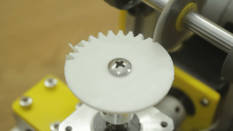
We’ve seen plenty of people 3D printing custom gears over the years, but [Mr Innovative] decided against an additive process for his bespoke component. He ended up using a simple CNC machine that makes use of several components that were either salvaged from a 3D printer or produced on one. Using a small saw blade, the machine cuts gear teeth into some plastic material and — presumably — could cut gears into anything the saw blade was able to slice into, especially if you added a little lubrication, cooling, and dust removal.

If you’ve built a 3D printer, you’ll see a lot of familiar parts. Stepper motors, aluminum extrusion, straight rods, bearing blocks, and rod holders are all used in the build. There’s also a lead screw and the associated components you usually see in a printer’s Z-axis. Naturally, an Arduino drives the whole affair.

The saw blade was custom-made from a washer, grinding an edge and using a 3D printed template to cut teeth in it. We might have been more inclined to use a cut-off wheel from a rotary tool, but this certainly did the trick. An LCD accepts the gear diameter and number of teeth. The stepper rotates the correct number of degrees and another stepper lowers the cutting head which is spinning with a common DC motor.

As impressive as this machine is, the fact remains that a 3D printer can produce more complex designs. For example, a herringbone pattern can help with alignment issues. It has been done many times. You can even use a resin printer, although you might prefer to stick with FDM.

In theory, there’s isn’t much to building a CNC machine. Hook a bit to a motor and move the motor around with some lead screws and stepper motors. Easy. But, of course, the devil is in the details. [DAZ] made a nice-looking and inexpensive rig that probably isn’t the most precise CNC in the world, but it looks like it does a good enough job and he claims he spent about $50 on it. The video below shows some of the work it has done, and it doesn’t look bad.

This isn’t a rainy afternoon project. You’ll need to cut some wood and 3D print many parts. The drives use M8 threaded rod. Electronics is just an Arduino running standard software.

The steppers looked pretty light duty, and we wondered if it would have been worthwhile to trade them out for beefier ones instead of modifying the ones used for bipolar operation. Still, the results did look good for $50. The 775 spindle is another place you could probably spend a little more and get something better. Non-printed linear rails, and a better screw? The point is that you’ve got a basis to build from.

We’ve seen cheap CNCs made from scrap before. If you decide an Arduino is too low-powered for your CNC, try going 32-bit.

Ask anybody whose spent time standing in front of a mill or lathe and they’ll tell you that some operations can get tedious. When you need to turn down a stainless rod by 1/4″ in 0.030″ increments, you get a lot of time to reflect on why you didn’t just buy the right size stock as you crank the wheel back and forth. That’s where the lead screw comes in — most lathes have a gear-driven lead screw that can be used to actuate the z-axis ( the one which travels parallel to the axis of rotation). It’s no CNC, but this type of gearing makes life easier and it’s been around for a long time.

[Tony Goacher] took this idea a few steps further when he created the Leadscrew Buddy. He coupled a beautiful 1949 Myford lathe with an Arduino, a stepper motor, and a handful of buttons to add some really useful capabilities to the antique machine. By decoupling the lead screw from the lathe’s gearbox and actuating it via a stepper motor, he achieved a much more granular variable feed speed.

If that’s not enough, [Tony] used a rotary encoder to display the cutting tool’s position on a home-built Digital Readout (DRO). The pièce de résistance is a “goto” command. Once [Tony] sets a home position, he can command the z-axis to travel to a set point at a given speed. Not only does this make turning easier, but it makes the process more repeatable and yields a smoother finish on the part.

These features may not seem so alien to those used to working with modern CNC lathes, but to the vast majority of us garage machinists, [Tony]’s implementation is an exciting look at how we can step up our turning game. It also fits nicely within the spectrum of lathe projects we’ve seen here at Hackaday- from the ultra low-tech to the ludicrously-precise.

Digitizing an object usually means firing up a CAD program and keeping the calipers handy, or using a 3D scanner to create a point cloud representing an object’s surfaces. [Dzl] took an entirely different approach with his DIY manual 3D digitizer, a laser-cut and 3D printed assembly that uses rotary encoders to create a turntable with an articulated “probe arm” attached.

Each joint of the arm is also an encoder, and by reading the encoder values and applying a bit of trigonometry, the relative position of the arm’s tip can be known at all times. Manually moving the tip of the arm from point to point on an object therefore creates measurements of that object. [Dzl] successfully created a prototype to test the idea, and the project files are available on GitHub.

We remember the earlier version of this project and it’s great to see how it’s been updated with improvements like the addition of a turntable with an encoder. DIY 3D digitizing takes all kinds of approaches, and one example was this unit that used four Raspberry Pi Zeros and four cameras to generate high quality 3D scans.

There is something fascinating about watching an autonomous machine. An automatic car wash, a soda vending machine that picks up the product behind a window, a plotter, or a robot like a CNC or 3D printer are all interesting to watch. Although [EngineerDog] bills Mug-O-Matic as a tiny CNC, we think it is more of a plotter for coffee mugs. It’s still fun to watch though, as you can see in the video below.

The design has about 60 printed parts and uses a Sharpie at the business end. It accepts gcode and can even emblazon your favorite mug with our own Jolly Wrencher, so you know we like it.

Of course, a Sharpie mark won’t stay on a mug forever, but the write up says you can bake the mug to make the markings permanent. At first, the project used a cheap Arduino Nano breakout board. However, that was set up to drive the servos with the Arduino’s power supply, so instead of board surgery there is now a custom PCB.

The resulting drawings are a little shaky, we aren’t sure if that’s from the way the device mounts on top of the mug or just the lever arm of the carriage the pen rides in. However, for a fun project it does a great job.

We couldn’t help but think about eggbots and the spherebot when we saw this. We also wondered if this could draw on glass that would later be etched with hydrofluoric acid or  Armour Etch.

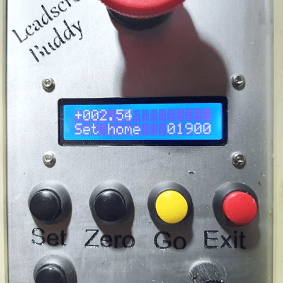
In a project, repetitive tasks that break the flow of development work are incredibly tiresome and even simple automation can make a world of difference. [Simon Merrett] ran into exactly this while testing different stepper motors in a strain-wave gear project. The system that drives the motor accepts G-Code, but he got fed up with the overhead needed just to make a stepper rotate for a bit on demand. His solution? A grbl man-in-the-middle jog pendant that consists of not much more than a rotary encoder and an Arduino Nano. The unit dutifully passes through any commands received from a host controller, but if the encoder knob is turned it sends custom G-Code allowing [Simon] to dial in a bit acceleration-controlled motor rotation on demand. A brief demo video is below, which gives an idea of how much easier it is to focus on the nuts-and-bolts end of hardware when some simple motor movement is just a knob twist away.

[Simon]’s jog pendant moves a single motor which is exactly what he needs to ease development of his 3D printed strain-wave gear using a timing belt, but it could be programmed with any G-Code at all. Speaking of DIY jog pendants for CNC machines, don’t forget this wireless one made from an Atari 2600 joystick that jogs a plasma cutter in X and Y, and zeroes it with a push of the button.


Filed under: Arduino Hacks, cnc hacks

This little DIY 64×64 graphical printer by [Egor] is part pen plotter in design, somewhat dot matrix-ish in operation, and cleverly designed to use unmodified 9G servos. The project page is all in Russian (translation to English here) but has plenty of photos that make the operation and design clear. Although nearly the entire thing is made from laser-cut wood, [Egor] says that a laser cutter is optional equipment. The first version was entirely cut with hand tools.

screenshot-2016-12-06-10-49-13Small DIY CNC machines driven over a serial line commonly use Arduinos and CD-ROM drive guts (like this Foam Cutter or this Laser Paper Cutter) but this build uses its own custom rack-and-pinion system, and has some great little added details like the spring-loaded clip to hold paper onto the print pad.

The frame and parts (including all gears) are laser-cut from 4 mm plywood and the unit is driven by three small servos. A simple Java program processes images and an Arduino UNO handles the low-level control. A video of everything in action is embedded below.

Speaking of rack-and-pinion setups using cheap servos, that idea was taken to the next level by this design for a 3-D printed linear actuator that uses unmodified servos.


Filed under: Arduino Hacks, cnc hacks

In this three part video series we watch [Dirk Herrendoerfer] go from scraps to a nice 3D printed assembly as he iterates through the design of a pen plotter for making circuit boards.

[dana] mentioned [Dirk]’s work in the comments of this post which describes a different process. Many permanent markers stick to copper well enough to last through the chemical etching process. While hand drawing definitely produces some cool, organic-looking boards, for sharp lines and SMDs it gets a bit harder; to the point where it becomes advisable to just let a robot do it.

Of course, [Dirk] was aware of this fact of life. He just didn’t have a robot on hand. He did have some electronic detritus, fishing line, an Arduino, scrap wood, brass tubes, and determination.  The first version‘s frame consisted of wooden blocks set on their ends with holes drilled to accept brass rods. The carriage was protoboard and hot glue. Slightly larger brass tubing served as bushings and guide. As primitive as it was the plotter performed admirably, albeit slowly.

The second version was a mechanical improvement over the first, but largely the same. The software got a nice improvement. It worked better and had some speed to it.

The latest version has some fancy software upgrades; such as acceleration. The frame has gone from random bits of shop trash to a nicely refined 3D printed assembly. Even the steppers have been changed to the popular 28BYJ-48 series. All the files, software and hardware, are available on GitHub. The three videos are viewable after the break. It’s a great example of what a good hacker can put together for practically no money.


Filed under: Arduino Hacks, cnc hacks

[gocivici] threatened us with a tutorial on positional astronomy when we started reading his tutorial on a Arduino Powered Star Pointer and he delivered. We’d pick him to help us take the One Ring to Mordor; we’d never get lost and his threat-delivery-rate makes him less likely to pull a Boromir.

As we mentioned he starts off with a really succinct and well written tutorial on celestial coordinates that antiquity would have killed to have. If we were writing a bit of code to do our own positional astronomy system, this is the tab we’d have open. Incidentally, that’s exactly what he encourages those who have followed the tutorial to do.

The star pointer itself is a high powered green laser pointer (battery powered), 3D printed parts, and an amalgam of fourteen dollars of Chinese tech cruft. The project uses two Arduino clones to process serial commands and manage two 28byj-48 stepper motors. The 2nd Arduino clone was purely to supplement the digital pins of the first; we paused a bit at that, but then we realized that import arduinos have gotten so cheap they probably are more affordable than an I2C breakout board or stepper driver these days. The body was designed with a mixture of Tinkercad and something we’d not heard of, OpenJsCAD.

Once it’s all assembled and tested the only thing left to do is go outside with your contraption. After making sure that you’ve followed all the local regulations for not pointing lasers at airplanes, point the laser at the north star. After that you can plug in any star coordinate and the laser will swing towards it and track its location in the sky. Pretty cool.


Filed under: Arduino Hacks, cnc hacks, news, solar hacks


  • Newsletter

    Sign up for the PlanetArduino Newsletter, which delivers the most popular articles via e-mail to your inbox every week. Just fill in the information below and submit.

  • Like Us on Facebook