Apparently not satisfied with a single PC monitor, aviation enthusiast Ryan H came up with his own custom, 3D-printable cockpit setup for the Garmin G1000 avionics suite. Designed around the X-Plane 11 flight simulator, the system uses a 12.1” LCD panel for flight data along with several additional inputs, all controlled by an Arduino Mega running SimVim firmware.
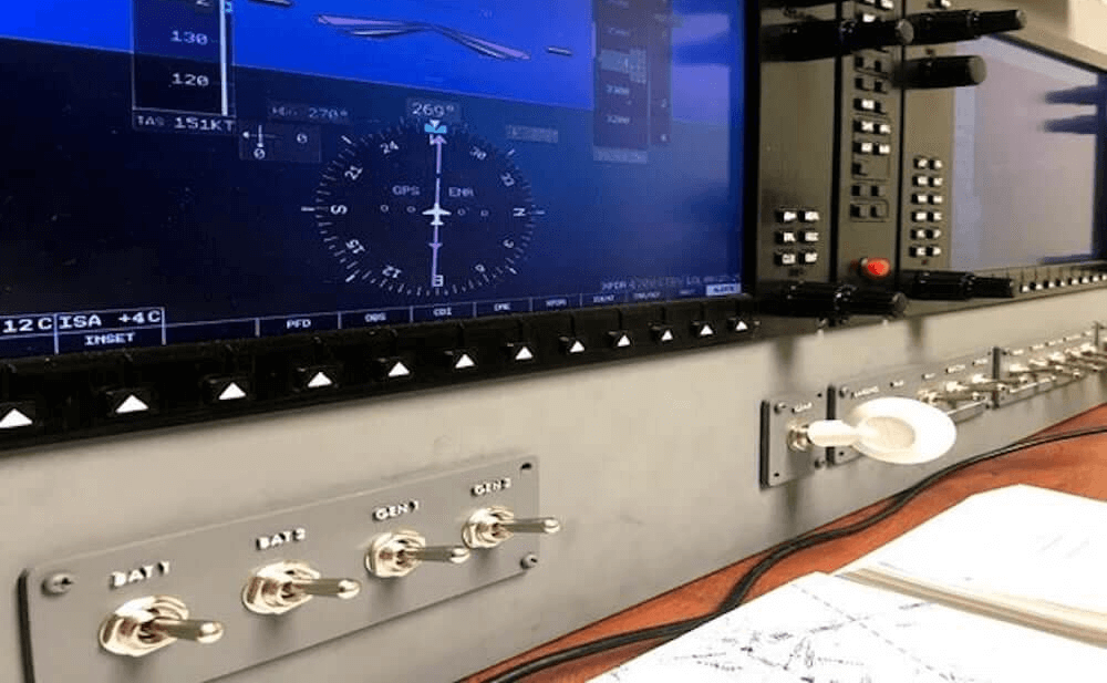
The auxiliary display/input assemblies interface with the Arduino, enabling it to handle 32 tactile switches plus one standard and five dual rotary encoders via five CD74HC4067 16-channel multiplexers.
Today’s commercial aircraft are packed to the elevators with sensors, computers, and miles and miles of wiring. Inside the cockpit you’re more than likely to see banks of LCDs and push buttons than analog gauges. So what’s that mean for the intrepid home simulator builder? Modern problems require modern solutions, and this 3D printed simulator is about as modern as it gets.
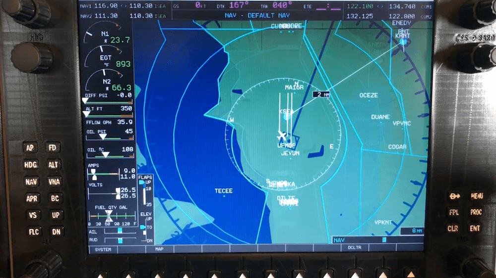
Published to Thingiverse by the aptly named [FlightSimMaker], this project consists of a dizzying number of 3D-printed components that combine into a full-featured desktop simulator for the Garmin G1000 avionics system. Everything from the parking brake lever to the push buttons in the display bezels was designed and printed: over 200 individual parts in all. Everything in this X-Plane 11 compatible simulator is controlled by an Arduino Mega 2560 with the SimVim firmware.
To help with connecting dozens of buttons, toggle switches, and rotary encoders to the Arduino, [FlightSimMaker] uses five CD74HC4067 16-channel multiplexers. The display is a 12.1 inch 1024 x 768 LCD panel with integrated driver, and comes in at the second most expensive part of the build behind the rotary encoders. All told, the estimated cost per display is around $250 USD.
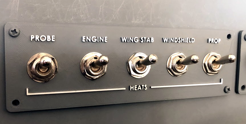
Even if you aren’t looking to build yourself a high-tech flight simulator, there’s plenty of ideas and tips here that could be useful for building front panels. We particularly like the technique used for doing 3D-printed lettering: the part is printed in white, spray painted a darker color, and then the paint is sanded off the faces of the letters to reveal the plastic. Even with a standard 0.4 mm nozzle, this results in clean high-contrast labels on the panel with minimal fuss.
Have you ever looked around your city’s layout and thought you could do better? Maybe you’ve always wanted to see how she’d run on nuclear or wind power, or just play around with civic amenities and see how your choices affect the citizens.
[Robbe Nagel] made this physical-digital simulator for a Creative Programming class within an industrial design program. We don’t have all the details, but as [Robbe] explains in the video after the break, each block has a resistor on the bottom, and each cubbyhole has a pair of contacts ready to mate with it. An Arduino nestled safely in the LEGO bunker below reads the different resistance values to determine what block was placed where.
[Robbe] wrote a program that evaluates various layouts and provides statistics for things like population, overall health, education level, pollution, etc. As you can see after the break, these values change as soon as blocks are added or removed. Part of what makes this simulator so cool is that it could be used for serious purposes, or it could be totally gamified.
It’s no secret that we like LEGO, especially as an enclosure material. Dress it up or dress it down, just don’t leave any pieces on the floor.
If you’ve done 3D printing, you’ve probably at least heard of Tinkercad. This popular CAD package runs in your browser and was rescued from oblivion by Autodesk a few years ago. [Chuck] recently did a video about a new Tinkercad feature: building and simulating virtual Arduino circuits. You can watch it below.
There are a variety of components you can add to your design. You’ll find an integrated code editor and a debugger. You can even get to the serial monitor, all in your browser with no actual Arduino hardware. You can also build simple circuits that don’t use an Arduino, although the component selection is somewhat limited.
This could be great for teaching Arduino in classrooms or when you want to do some development in a hotel room. The layout is very visual, so if you are accustomed to reading schematics, you may not appreciate the style. In addition, the selection of components is somewhat limited (including only supporting the Arduino UNO, as far as we could tell). So for educational purposes, it is great. For breadboarding your next great Arduino-powered robot, maybe not so much.
If you remember Circuits123 (or circuits.io), this is the same underlying technology. They’ve just integrated it with Tinkercad. However, there doesn’t seem to be any real integration between the two other than they are on the same web page now. Perhaps in the future, they’ll let you drop components on the circuit that also show up in the 3D design (or, at least, with sockets or holders for those components).
However, having a simulated Arduino with a debugger could come in handy even if you don’t care about the circuit simulations. If you really want to do circuit simulation, it is hard to go wrong with LTSpice. If you really want it to be in your browser, there’s always Falstad.
In this review of an older kit (circa 1993~1997) we examine the Diesel Sound Simulator for Model Railroads kit from (the now defunct) Dick Smith Electronics, based on the article published in the December 1992 issue of Silicon Chip magazine.
The purpose of this kit is to give you a small circuit which can fit in a HO scale (or larger) locomotive, or hidden underneath the layout – that can emulate the rumbling of a diesel-electric locomotive to increase the realism of a train. However the kit is designed for use with a PWM train controller (also devised by Silicon Chip!) so not for the simple direct-DC drive layouts.
Assembly
The diesel sound kit was from the time when DSE still cared about kits, so you received the sixteen page “Guide to Kit Construction” plus the kit instructions, nasty red disclaimer sheet, feedback card, plus all the required components and the obligatory coil of solder that was usually rubbish:
Everything required to get going is included, except IC sockets. My theory is it’s cheaper to use your own sockets than source older CMOS/TTL later on if you want to reuse the ICs, so sockets are now mandatory here:
The PCB is from the old school of “figure-it-out-yourself”, no fancy silk-screening here:
Notice the five horizontal pads between the two ICs – these were for wire bridges in case you needed to break the PCB in two to fit inside your locomotive.
Actual assembly was straight-forward, all the components went in without any issues. Having two links under IC2 was a little annoying, however a short while later the PCB was finished and the speaker attached:
How it works
As mentioned earlier this diesel sound kit was designed for use with the Silicon Chip train PWM controller, so the design is a little different than expected. It can handle a voltage of around 20 V, and the sound is determined by the speed of the locomotive.
The speed is determined by the back EMF measured from the motor – and (from the manual) this is the voltage produced by the motor which opposes the current flow through it and this voltage is directly proportional to speed.
Not having a 20V DC PWM supply laying about I knocked up an Arduino to PWM a 20V DC supply via an N-MOSFET module and experimented with the duty cycle to see what sort of noises could be possible. The output was affected somewhat by the supply voltage, however seemed a little higher in pitch than expected.
You can listen to the results in the following video:
I reckon the sound from around the twenty second mark isn’t a bad idle noise, however in general not that great. The results will ultimately be a function of a lower duty-cycle than I could create at the time and the values of R1 and R2 used in the kit.
Conclusion
Another kit review over. With some time spent experimenting you could generate the required diesel sounds, a Paxman-Valenta it isn’t… but it was a fun kit and I’m sure it was well-received at the time. To those who have been asking me privately, no I don’t have a secret line to some underground warehouse of old kits – just keep an eye out on ebay and they pop up now and again. Full-sized images and much more information about the kit are available on flickr.
And while you’re here – are you interested in Arduino? Check out my new book “Arduino Workshop” from No Starch Press.
In the meanwhile have fun and keep checking into tronixstuff.com. Why not follow things on twitter, Google+, subscribe for email updates or RSS using the links on the right-hand column? And join our friendly Google Group – dedicated to the projects and related items on this website. Sign up – it’s free, helpful to each other – and we can all learn something.
Dominick Lee is a programmer, inventor who created the “LifeBeam Flight Simulator“, a pneumatic-powered dual-axis motion flight simulator using Arduino Duemilanove. After a few months of diligent work and the help of some generous collaborators he was able to mix physics, robotic and aviation into a motion platform that can make full rotations tilting at about 40 degrees.
The LifeBeam Flight Simulator is a full setup of equipment that runs simultaneously and collaboratively. The data is first sent from the Graphics or “Gaming PC” through a custom software program that acquires game data. The game data is scaled and converted into specific coordinates for the roll and pitch (X and Y) axis. The program sends out the final signal which is received by an Arduino (Duemilanove). The Arduino has a complex program on it that combines the serial commands and parses certain values to calculate a voltage which is then converted into PWM and sent to a low-pass filter which smoothes the PWM into analog voltage. The analog voltage is connected to a Pneumatic Valve Amplifier which controls the pneumatic cylinders to make the platform move accordingly.
Planet Arduino is, or at the moment is wishing to become, an aggregation of public weblogs from around the world written by people who develop, play, think on Arduino platform and his son. The opinions expressed in those weblogs and hence this aggregation are those of the original authors. Entries on this page are owned by their authors. We do not edit, endorse or vouch for the contents of individual posts. For more information about Arduino please visit www.arduino.cc
You are currently browsing the archives for the simulator category.