It’s a well-known fact in capitalist societies that any product or service, if being used in a wedding, instantly triples in cost. Wanting to avoid shelling out big money for a simple photo booth for a friend’s big day, [Lewis] decided to build his own.
Wanting a quality photo output, a Canon DSLR was selected to perform photographic duties. An Arduino Nano is then pressed into service to run the show. It’s hooked up to a MAX7219 LED matrix which feeds instructions to the willing participants, who activate the system with a giant glowing arcade button. When pressed, the Nano waits ten seconds and triggers the camera shutter, doing so three times. Images are displayed on a screen hooked up to the camera’s USB port.
It’s a build that keeps things simple. No single-board PCs needed, just a camera, an Arduino, and a monitor for the display. We’re sure the wedding-goers had a great time, and we look forward to seeing what [Lewis] comes up with next. We’ve seen a few of his hacks around here before, too.
Have you built a 3D scanner yet? There’s more than one way to model those curves and planes, but the easiest may be photogrammetry — that’s the one where you take a bunch of pictures and stitch them into a 3D model. If you build a scanner like [Brian Brocken]’s that does almost everything automatically, you might consider starting a scan-and-print side hustle.
This little machine spins objects 360° and triggers a Bluetooth remote tethered to an iPhone. In automatic mode, it capture anywhere from 2-200 pictures. There’s a mode for cinematic shots that shoots video of the object slowly spinning around, which makes anything look at least 35% more awesome. A third mode offers manual control of the turntable’s position and speed.
An Arduino UNO controls a stepper that moves the turntable via 3D printed-in-place bearing assembly. This project is a (vast) improvement over [Brian]’s hand-cranked version that we looked at over the summer, though both are works of art in their own right.
Our favorite part aside from the bearing is the picture-taking process itself. [Brian] couldn’t get the iPhone to play nice with HC-05 or -06 modules, so he’s got the horn of 9g servo tapping the shutter button on a Bluetooth remote. This beautiful beast is wide open, so fire up that printer. You can watch the design and build process of the turntable after the break.
[JBumstead] didn’t want an ordinary microscope. He wanted one that would show the big picture, and not just in a euphemistic sense, either. The problem though is one of resolution. The higher the resolution in an image — typically — the narrower the field of view given the same optics, which makes sense, right? The more you zoom in, the less area you can see. His solution was to create a microscope using a conventional camera and building a motion stage that would capture multiple high-resolution photographs. Then the multiple photos are stitched together into a single image. This allows his microscope to take a picture of a 90x60mm area with a resolution of about 15 μm. In theory, the resolution might be as good as 2 μm, but it is hard to measure the resolution accurately at that scale.
As an Arduino project, this isn’t that difficult. It’s akin to a plotter or an XY table for a 3D printer — just some stepper motors and linear motion hardware. However, the base needs to be very stable. We learned a lot about the optics side, though.
Two Nikon lenses and an aperture stop made from black posterboard formed a credible 3X magnification element. We also learned about numerical aperture and its relationship to depth of field.
One place the project could improve is in the software department. Once you’ve taken a slew of images, they need to blend together. It can be done manually, of course, but that’s no fun. There’s also a MATLAB script that attempts to automatically stitch the images together, blending the edges together. According to the author, the code needs some work to be totally reliable. There are also off-the-shelf stitching solutions, which might work better.
Before going into the journalism program at Centennial College in Toronto, [Carolyn Pioro] was a trapeze performer. Unfortunately a mishap in 2005 ended her career as an aerialist when she severed her spinal cord, leaving her paralyzed from the shoulders down. There’s plenty of options in the realm of speech-to-text technology which enables her to write on the computer, but when she tried to find a commercial offering which would let her point and shoot a DSLR camera with her voice, she came up empty.
[Taras Slawnych] heard about [Carolyn’s] need for special camera equipment and figured he had the experience to do something about it. With an Arduino and a couple of servos to drive the pan-tilt mechanism, he came up with a small device which Carolyn can now use to control a Canon camera mounted to an arm on her wheelchair. There’s still some room for improvement (notably, the focus can’t be controlled via voice currently), but even in this early form the gadget has caught the attention of Canon’s Canadian division.
With a lavalier microphone on the operator’s shirt, simple voice commands like “right” and “left” are picked up and interpreted by the Arduino inside the device’s 3D printed case. The Arduino then moves the appropriate servo motor a set number of degrees. This doesn’t allow for particularly fine-tuned positioning, but when combined with movements of the wheelchair itself, gives the user an acceptable level of control. [Taras] says the whole setup is powered off of the electric wheelchair’s 24 VDC batteries, with a step-down converter to get it to a safe voltage for the Arduino and servos.
Taking pictures in the 21st century is incredibly easy. So easy in fact that most people don’t even own a dedicated camera; from smartphones to door bells there are cameras built into nearly electronic device we own. So in this era of ubiquitous photography, you might think that a very slow and extremely low resolution camera wouldn’t be of interest. Under normal circumstances that’s probably true, but this single pixel camera built by [Tucker Shannon] is anything but normal.
At the heart of his unusual camera is the TCS34725 RGB color sensor from Adafruit which receives a tightly focused beam of incoming light by way of a 3D printed enclosure and a 3mm OD aluminum tube. This allows an Arduino Uno to determine the color of this tiny slice of light, making up a single pixel of the final color image. [Tucker] notes that you could even swap the color sensor out for a simple photocell if you don’t mind a black & white image at the end of the process.
In either event, once the light has been analyzed the sensor is repositioned autoturret-style by way of dual BYJ-48 stepper motors. This process continues on, spiraling outwards until the whole image is stitched together from these individual readings
Now compared to the camera in your phone, the resulting image might be a bit underwhelming. We’d say it’s a bit like looking at a digital picture on an 8 bit computer, but in truth even that might be overly generous. But even if it isn’t as crisp as modern eyes would like there’s no question that it’s certainly a recognizable image, which is all [Tucker] was shooting for.
Light painting: there’s something that never gets old about waving lights around in a long exposure photo. Whilst most light paintings are single shots, some artists painstakingly create frame-by-frame animations. This is pretty hard to do when moving a light around by hand: it’s mostly guesswork, as it’s difficult to see the results of your efforts until after the photo has been taken. But what if you could make the patterns really precise? What if you could model them in 3D?
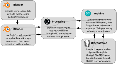
[Josh Sheldon] has done just that, by creating a process which allows animations formed in Blender to be traced out in 3D as light paintings. An animation is created in Blender then each frame is automatically exported and traced out by an RGB LED on a 3D gantry. This project is the culmination of a lot of software, electronic and mechanical work, all coming together under tight tolerances, and [Josh]’s skill really shines.
The first step was to export the animations out of Blender. Thanks to its open source nature, Python Blender add-ons were written to create light paths and convert them into an efficient sequence that could be executed by the hardware. To accommodate smooth sliding camera movements during the animation, a motion controller add-on was also written.
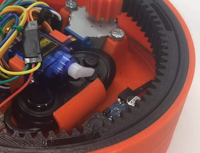
The gantry which carried the main LED was hand-made. We’d have been tempted to buy a 3D printer and hack it for this purpose, but [Josh] did a fantastic job on the mechanical build, gaining a solidly constructed gantry with a large range. The driver electronics were also slickly executed, with custom rack-mount units created to integrate with the DragonFrame controller used for the animation.
The video ends on a call to action: due to moving out, [Josh] was unable to continue the project but has done much of the necessary legwork. We’d love to see this project continued, and it has been documented for anyone who wishes to do so. If you want to check out more of [Josh]’s work, we’ve previously written about that time he made an automatic hole puncher for music box spools.
Photography turntables are made for both the precise and lazy. Whether you are concerned about the precision of consistent angles during a photo shoot or you simply do not want to stand there rotating a plate after every picture — yes, it does get old — a lazy susan style automatic photography turntable is the ticket. This automatic 360° design made over at circuito.io satisfies both of these needs in an understated package.
The parts required to make this DIY weekend project are about as minimal as they get. An Arduino Uno controls it all with a rotary encoder for input and a character LCD to display settings. The turntable moves using a stepper motor and an EasyDriver. It even takes care of controlling the camera using an IR LED.
The biggest obstruction most likely to arise is creating the actual laser cut casing itself. The circuito team avoided this difficulty by using Pololu‘s online custom laser cutting service for the 4 necessary laser cut parts. After all of the components have been brought together, all that is left to do is Avengers assemble. They provide step by step instructions for this process in such a straightforward way that you could probably put this sucker together blindfolded.
We have seen some other inspired photography turntables on Hackaday before. [NotionSunday] created a true turntable hack based off of the eject mechanism of an old DVD-ROM drive. With the whole thing spinning on the head assembly of a VCR, this is the epitome of letting nothing go to waste. We also displayed another very similar Arduino Uno controlled turntable created 2 years ago by [Tiffany Tseng]. There is even a non-electronic version out there of a DIY 360° photography turntable that only uses a lazy susan and tape measure. All of these photography turntable hacks do the job wonderfully, but there was something that we liked about the clean feel of this one. All of the necessary code for this project has been provided over at GitHub. What is your favorite photography turntable?
It can be hard enough to take a good photograph of a running kid or pet, and if we’re being honest, sometimes even stationary objects manage to allude our focus. Now imagine trying to take a picture of something moving really fast, like a bullet. Trying to capture the moment a fast moving projectile hits an object is simply not possible with a human behind the shutter button.
Enter the ballistic chronometer: a device that uses a set of sensor gates and a highly accurate timer to determine how fast an object is flying through it. Chronometers that operate up to a couple hundred meters per second are relatively common, but [td0g] had something a little faster in mind. He’s come up with an optical setup that he claims can capture objects moving as fast as Mach 2. With this chronometer tied into a high-speed flash rig, [td0g] is able to capture incredible shots such as the precise instant a bullet shatters a glass of water.
Because he couldn’t find any phototransistors with the sub-microsecond response time necessary to detect a small object moving at 1,000 m/s, [td0g] ended up using LEDs in a photoconductive configuration, where 27 VDC is applied backwards against the diode. Careful monitoring of voltage fluctuations across the diode allows for detection of changes in the received light level. To cut down on interference, [td0g] used IR LEDs as his light sources, reasoning there would be less ambient IR than if he used something in the visual range.
What really impresses with this build is the attention to detail and amount of polish [td0g] put into the design. From the slick angled bracket that holds the Arduino and LCD to the 3D printed covers over the optical gates, the final device looks like a professional piece of equipment with a price tag to rival that of a used car.
For the future, [td0g] plans on upgrading to faster comparators than he LM339’s he has installed currently, and springing for professionally done PCBs instead of protoboard. In it’s current state this is already a very impressive piece of kit, so we’d love to see what it looks like when it’s “finished”.
It’s 2017 and even GoPro cameras now come with voice activation. Budding videographers, rest assured, nothing will look more professional than repeatedly yelling at your camera on a big shoot. Hackaday alumnus [Jeremy Cook] heard about this and instead of seeing an annoying gimmick, saw possibilities. Could they automate their GoPro using Arduino-spoken voice commands?
It’s an original way to do automation, for sure. In many ways, it makes sense – rather than mucking around with trying to make your own version of the GoPro mobile app (software written by surfers; horribly buggy) or official WiFi remote, stick with what you know. [Jeremy] decided to pair an Arduino Nano with the ISD1820 voice playback module. This was then combined with a servo-based panning fixture – [Jeremy] wants the GoPro to pan, take a photo, and repeat. The Arduino sets the servo position, then commands the ISD1820 to playback the voice command to take a picture, before rotating again.
[Jeremy] reports that it’s just a prototype at this stage, and works only inconsistently. This could perhaps be an issue of intelligibility of the recorded speech, or perhaps a volume issue. It’s hard to argue that a voice control system will ever be as robust as remote controlling a camera over WiFi, but it just goes to show – there’s never just one way to get the job done. We’ve seen people go deeper into GoPro hacking though – check out this comprehensive guide on how to pwn your GoPro.
Industrial hardware needs to be reliable, tough, and interoperable. For this reason, there are a series of standards used for command & control connections between equipment. One of the more widespread standards is ModBus, an open protocol using a master-slave architecture, usually delivered over RS-485 serial. It’s readily found being used with PLCs, HMIs, VFDs, and all manner of other industrial equipment that comes with a TLA (three letter acronym).
[Absolutelyautomation] decided to leverage ModBus to control garden variety digital cameras, of the type found cluttering up drawers now that smartphones have come so far. This involves getting old-school, by simply soldering wires to the buttons of the camera, and using an Arduino Nano to control the camera while talking to the ModBus network.
This system could prove handy for integrating a camera into an industrial production process to monitor for faults or defective parts. The article demonstrates simple control of the camera with off-the-shelf commercial PLC hardware. Generally, industrial cameras are very expensive, so this hack may be useful where there isn’t the budget for a proper solution. Will it stand up to industrial conditions for 10 years without missing a beat? No, but it could definitely save the day in the short term for a throwaway price. One shortfall is that the camera as installed will only save pictures to its local memory card. There’s a lot to be said for serving the images right to the engineer’s desk over a network.
Planet Arduino is, or at the moment is wishing to become, an aggregation of public weblogs from around the world written by people who develop, play, think on Arduino platform and his son. The opinions expressed in those weblogs and hence this aggregation are those of the original authors. Entries on this page are owned by their authors. We do not edit, endorse or vouch for the contents of individual posts. For more information about Arduino please visit www.arduino.cc
You are currently browsing the archives for the digital cameras hacks category.