Drums are an exciting instrument to learn to play, but often prohibitive if there are housemates or close neighbors involved. For that problem there are still electronic drums which can be played much more quietly, but then the problem becomes one of price. To solve at least part of that one, [Jeremy] turned to using an Arduino to build a drum module on his own, but he still had to solve yet a third problem: how to make the Arduino fast enough for the drums to sound natural.
Playing music in real life requires precise timing, so the choice of C++ as a language poses some problems as it’s not typically as fast as lower-level languages. It is much easier to work with though, and [Jeremy] explains this in great detail over a series of blog posts detailing his drum kit’s design. Some of the solutions to the software timing are made up for with the hardware on the specific Arduino he chose to use, including an even system, a speedy EEPROM, hardware timers, and an ADC that can sample at 150k samples per second.
With that being said, the hardware isn’t the only thing standing out on this build. [Jeremy] has released the source code on his GitHub page for those curious about the build, and is planning on releasing several more blog posts about the drum kit build in the near future as well. This isn’t the only path to electronic drums, though, as we’ve seen with this build which converts an analog drumset into a digital one.
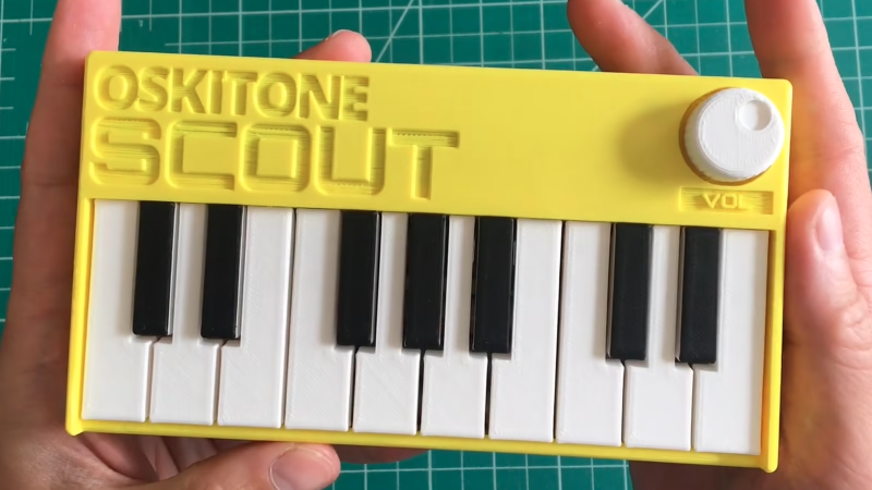
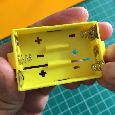
We’ve always been delighted with the thoughtful and detailed write-ups that accompany each of [Tommy]’s synth products, and the background of his newest instrument, the Scout, is no exception. The Scout is specifically designed to be beginner-friendly, hackable, and uses 3D printed parts and components as much as possible. But there is much more to effectively using 3D printing as a production method than simply churning out parts. Everything needed to be carefully designed and tested, including the 3D printed battery holder, which we happen to think is a great idea.
3D printed battery holder, with spring contacts inserted by hand.
[Tommy] also spends some time explaining how he decided which features and design elements to include and which to leave out, contrasting the Scout with his POLY555 synth. Since the Scout is designed to be affordable and beginner-friendly, too many features can in fact be a drawback. Component costs go up, assembly becomes less straightforward, and more complex parts means additional failure points when 3D printing.
[Tommy] opted to keep the Scout tightly focused, but since it’s entirely open-sourced with a hackable design, adding features is made as easy as can be. [Tommy] designed the PCB in KiCad and used OpenSCAD for everything else. The Scout uses the ATmega328, and can be easily modified using the Arduino IDE.
Two engineering students are hard at work on this air drum which they hope will help disabled people and people in nursing homes. Though, we think it just looks fun!
Each board is its own module consisting of the electronics and 3D printed cases. The modules each contain an arduino mini, IR sensor, and LEDs. They share power, audio, and communicate with an i2c bus. Two modules are special, one holds the power system and the other a Raspberry Pi. The units can be put together in different configurations. Finally, they are capped with speaker units.
The demo shown in the video, which you can see after the break, looks fun. The response time is pretty fast and it looks like you can measure all sorts of parameters. This can then be translated into different velocities, pitches, and instruments. It’s somewhere between a theremin and a drum kit, very cool.
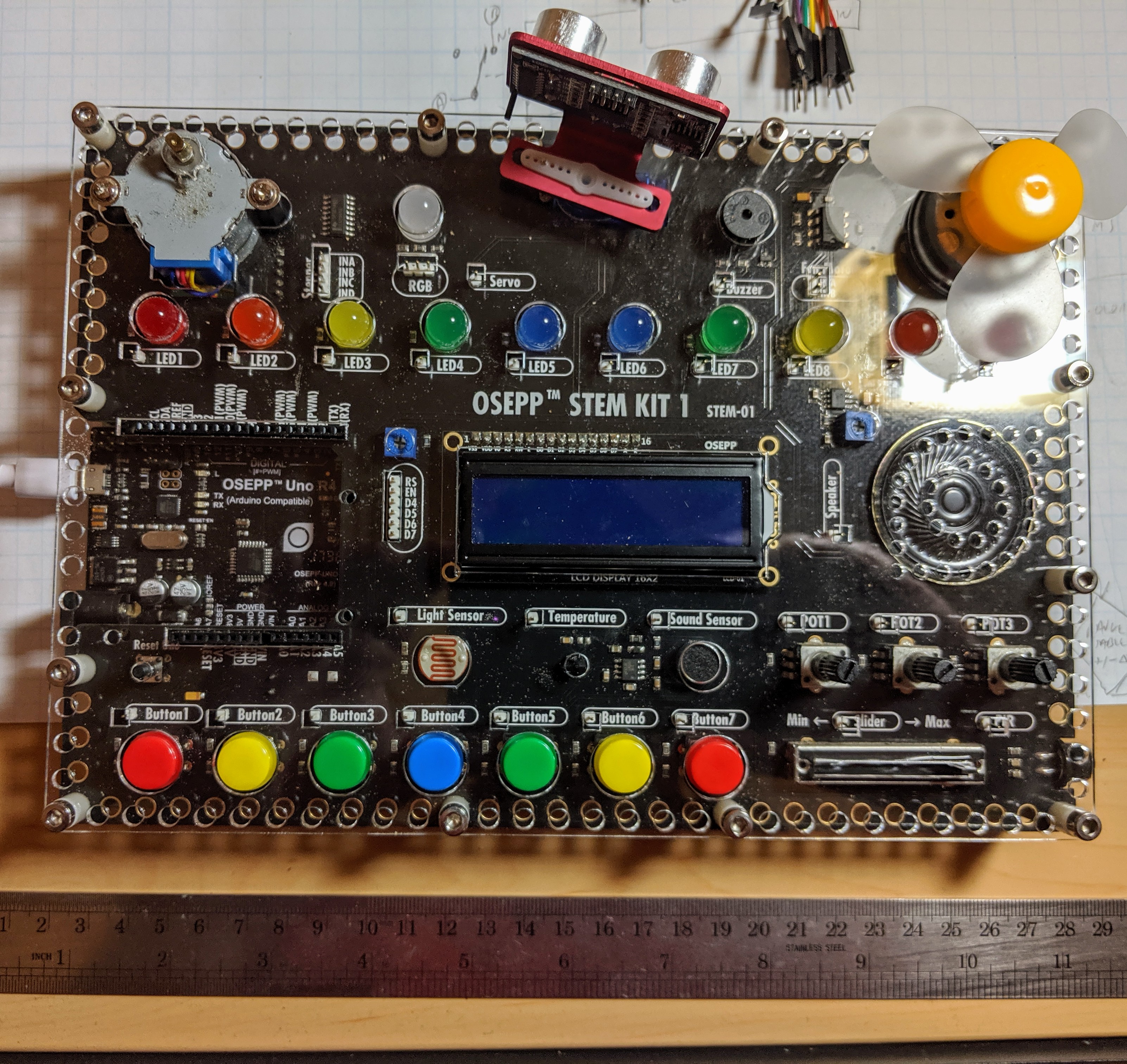
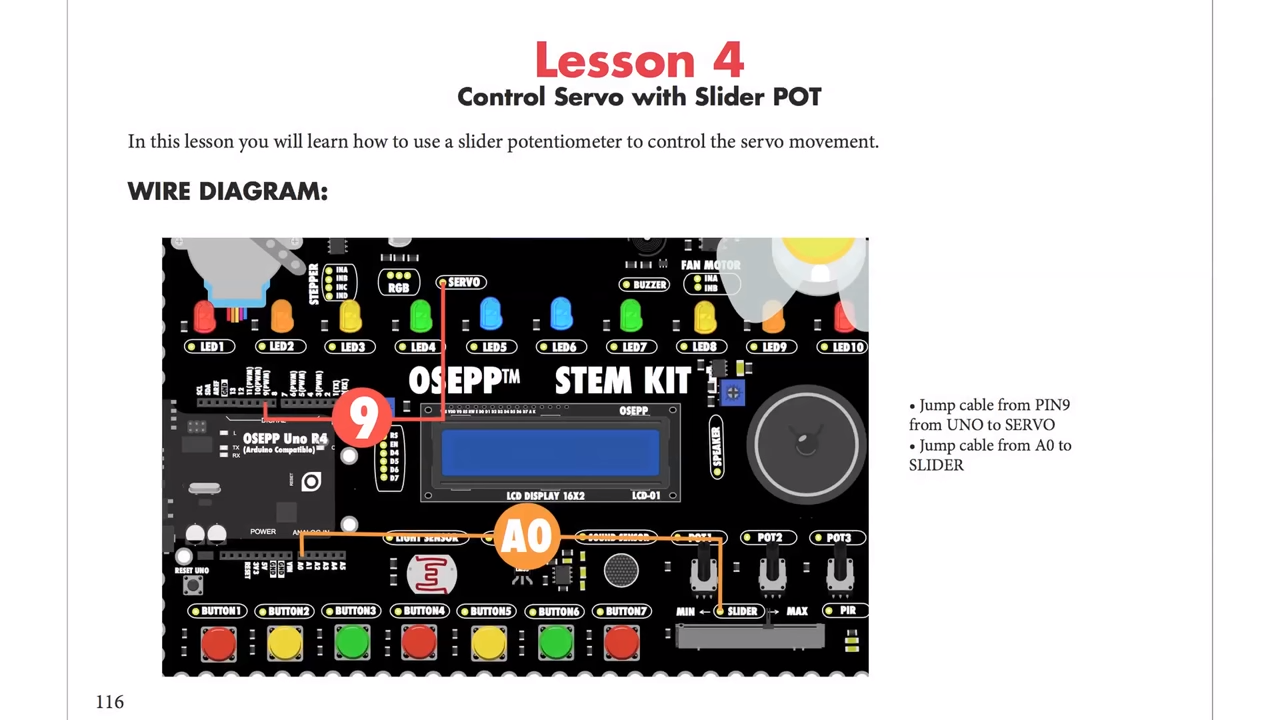
As the name implies, the OSEP STEM board is an embedded project board primarily aimed at education. You use jumper wires to connect components and a visual block coding language to make it go.
I have fond memories of kits from companies like Radio Shack that had dozens of parts on a board, with spring terminals to connect them with jumper wires. Advertised with clickbait titles like “200 in 1”, you’d get a book showing how to wire the parts to make a radio, or an alarm, or a light blinker, or whatever.
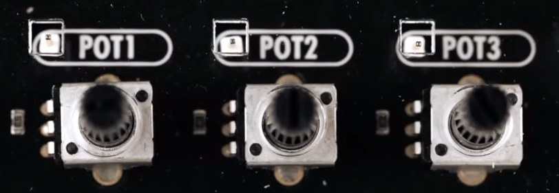
The STEM Kit 1 is sort of a modern arduino-powered version of these kits. The board hosts a stand-alone Arduino UNO clone (included with the kit) and also has a host of things you might want to hook to it. Things like the speakers and stepper motors have drivers on board so you can easily drive them from the arduino. You get a bunch of jumper wires to make the connections, too. Most things that need to be connected to something permanently (like ground) are prewired on the PCB. The other connections use a single pin. You can see this arrangement with the three rotary pots which have a single pin next to the label (“POT1”, etc.).
I’m a sucker for a sale, so when I saw a local store had OSEPP’s STEM board for about $30, I had to pick one up. The suggested price for these boards is $150, but most of the time I see them listed for about $100. At the deeply discounted price I couldn’t resist checking it out.
So does an embedded many-in-one project kit like this one live up to that legacy? I spent some time with the board. Bottom line, if you can find a deal on the price I think it’s worth it. At full price, perhaps not. Join me after the break as I walk through what the OSEPP has to offer.
What’s Onboard?
There are plenty of input and output devices:
7 Push Buttons
Potentiometers (3 rotary and 1 slide)
Passive Infrared Sensor (PIR)
Light Sensor
Sound Sensor
LM35 Temperature Sensor
10 LEDs (various colors)
Servo Motor
Stepper Motor
DC Motor
LCD Display
Buzzer
Speaker
RGB LED
In addition, the kit comes with an ultrasonic distance sensor in a little bracket that can connect to the stepper motor. That’s the only part that needs power and ground that isn’t already wired up.
Because the heart of the board is an Arduino UNO clone, you can do anything you like to program it. However, OSEPP touts their visual block diagram language that is basically Scratch. You can use it for free on most platforms and there is even a Web-based version although it can’t download code. It looks like Scratch or other block-oriented systems you’ve seen before.
I’m not usually fond of the visual block languages, but this one at least shows you the actual Arduino code it generates, so that isn’t bad. But you can still use any other method you like such as the standard IDE or PlatformIO.
You can see a video about the board, below.
The Good and the Bad
The board feels substantial and able to withstand a good bit of abuse. There’s a good range of components, and I like that the arduino is a real daughter board and not just built onto the PCB. Despite using the block language, I do like the tutorial booklet. It is very slick and has projects ranging from an IR doorbell to a mini piano. You can see a page below — very colorful and clear.
Of course, the suggested retail price of $150 is a bit offputting. You might think a breadboard with a handful of LEDs and other parts would be a much lower-cost option but just look around for arduino kits for beginners and you’ll find prices are all over the place. On the other hand, with a parts kit you would have to know how to wire up things like stepper motors or DC motors, so there is some value to having it already done for you. There’s also value in not having a bag of parts to misplace.
The jumper wires in the kit have pins on one side and sockets on the other. The pins go into the Arduino’s connector and the sockets go over pins on the components. These aren’t quite as reliable as a spring clip and not as versatile either.
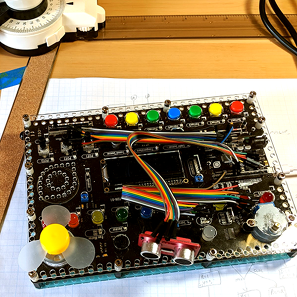
In my mind the worst part of the kit design is that the pins are right next to each of the components. That’s good for understanding, but it makes a mess of wiring. For instance, there are ten LEDs, and connecting them all means stretching jumper wires to both edges of the board The jumpers aren’t very long either, so any complex project is going to have wires crisscrossing the sensors and LCD.
Granted, in this image I could have removed some of the wires from the bundles but that wouldn’t help that much, either. If you need to hook up more than a few of the available components you will have a mess. I would have put some sort of spring clip or even screw terminals and put them all on the top and bottom of the board with clear color-coded marking about where they connect. Then the wiring would all be out of the way. There are probably a few other ways they could have gone, and at this price, they could afford the few extra inches on the PCB.
There are a few other things that would have been nice touches to finish off this kit. I would have enjoyed a short chapter in the booklet about using the Arduino IDE directly so that people know it exists. And having even a small breadboard attached for your own exploration would make sense, but would then call for a different type of jumper wire.
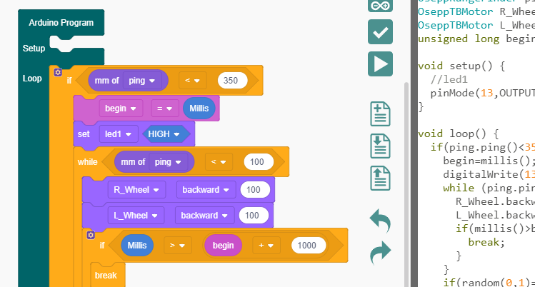
Short Example Using the Distance Sensor
I wanted to do something with the board so I decided to play with the distance sensor and the servo. The distance sensor is a bit annoying both because you have to wire it all up and it has a tendency to fall off when you transport the board.
The demo (you can find it online) won’t win any originality prizes. The program moves the servo to scan from 0 to 180 degrees in 5 degree increments. It measures the distance of what’s in front of it. When it completes a scan, if it saw something close (you could adjust the sensitivity), it moves the sensor back to that position and waits 30 seconds. Otherwise, it keeps scanning.
Really, this is no different from any other Arduino program. That’s kind of the point. Despite the emphasis in the book on the point-and-click language, this is really just an Arduino.
In Summary
For the deep sale price I found, the board will work well for its intended audience of students or anyone starting out with Arduino or microcontrollers. Even a more advanced audience who just wants a way to hammer out a quick prototype might find it worth the $30 or $40 you can sometimes pay. But at full price, it is hard to imagine this makes sense because of the mess of wire routing and limited expansion options.
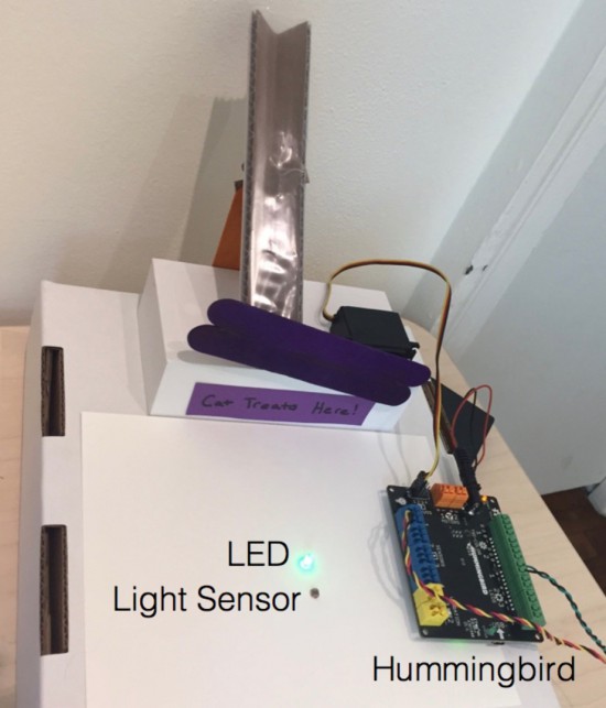
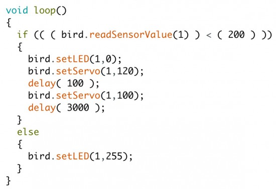
The Hummingbird by BirdBrain Technologies is an Arduino AtHeart microcontroller designed to enable beginners to create robots from craft materials. Hummingbird kits include LEDs, motors, and sensors that connect directly to the board. This eliminates the need for soldering or breadboarding and ensures that users have the parts they need to build their first robots. All of the components are reusable, so the same kit can be used to build many different robots.
In addition, the Hummingbird supports a variety of programming options, making it appropriate for beginning programmers as well as those who are more advanced. Some programming languages, such as Scratch and Snap!, can only be used when the board is connected to the computer. We will concentrate here on programming alternatives that enable users to upload a program onto the board’s Arduino.
Classrooms all over the world have used the Hummingbird from elementary to high school for projects ranging from Shakespeare dioramas to the physics of amusement park rides. In the following project, the BirdBrain Technologies team will show how they used the Hummingbird to build an automatic cat treat dispenser and demonstrate how the Hummingbird can be utilized to construct robots from everyday materials.
Building with the Hummingbird
Beginners can easily get started building Hummingbird robots with cardboard and craft materials. Motors, sensors, and LEDs can be connected directly to the Hummingbird board, and these elements can be added to the robot with hot glue. Hot glue peels off the components so that they can later be reused.
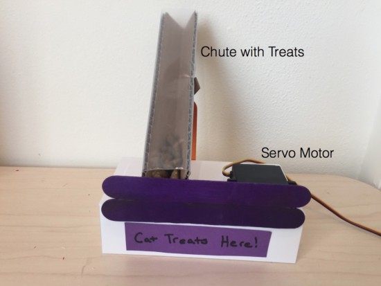
The example project uses one servo motor, one single color LED, and a light sensor. The dispenser consists of a servo motor attached to craft sticks that block the bottom of a chute containing cat treats. The position of the servo motor can be changed in software to release treats.
To receive a treat, the cat must cover a light sensor in front of the chute. When the cat covers the sensor, the servo motor briefly moves to open the chute and dispense a treat. The LED was included to show our test cat the location of the light sensor.
Programming with the Hummingbird
One unique feature of the Hummingbird is that it supports three different programming options for producing an Arduino program. These options provide steps of increasing difficulty to support learners as they transition from programming novices to Arduino experts.
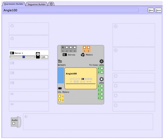
Beginners can start with the CREATE Lab Visual Programmer. This software option is based on storyboarding. Users can select the motors and LEDs that they are using on a schematic of the Hummingbird board. Then they can create expressions by using sliders to set the values of these outputs. The expression below sets a servo motor to 100°.
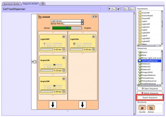
Expressions can be combined to create sequences. For example, the sequence below controls our automatic cat treat dispenser. This sequence is controlled by a sensor block. If the light level is low, the three expressions on the left are executed. If the light level is high, the three expressions on the right are executed. The user can then convert this sequence to an Arduino program by simply clicking the “Export Sequence” button (shown outlined in red). The Hummingbird can then be placed into Arduino mode and the program uploaded to the microcontroller.
Another option for beginners is ArduBlock, which provides a visual introduction to the Arduino language. The Hummingbird extension for ArduBlock includes a block for each Hummingbird component. A program in ArduBlock to control the treat dispenser is shown below. This program is equivalent to the CREATE Lab Visual Programmer sequence shown above.
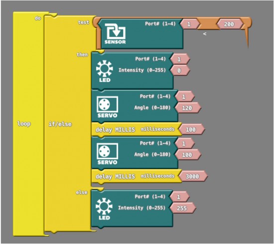
The Arduino code generated by this ArduBlock program is shown below. Individuals moving from the CREATE Lab Visual Programmer or ArduBlock to Arduino can start by modifying the generated code. For example, in the video we modified the commands inside the else to make the LED blink to attract the cat’s attention.
Once individuals are comfortable with the Arduino programming language, they can create more complex programs in Arduino. For instance, the video shows how we modified our robot and our code to incorporate three lights and three sensors. To get a treat, the cat must cover the sensor when the corresponding light is on.
The cat treat dispenser is only one example of a Hummingbird robot using the power of the Arduino at its core. The parts can be used and reused to construct an unlimited number of robots with low-cost materials such as cardboard, pipe cleaners, recycled materials, and even paper mache!
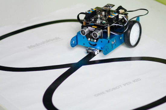
mBot it’s an all-in-one solution for kids and beginners to enjoy the hands-on experience about robotics, programming, and electronics.
You can program it with drag-and-drop graphical programming software based on Scratch 2.0 and the magic happens: the robots can follow lines, kick balls and push objects, avoid walls and more. You can also switch from graphical to text-based programming in Arduino mode as it can be coded with Arduino IDE environment.
Watch the video of their successful Kickstarter campaign:
mBot supports wireless communication, standard Arduino boards like Arduino Uno, Leonardo boards, Arduino Nano, Arduino Mega 2560, Makeblock mCore (based on Arduino Uno).
The main control board’s design, mCore of mBot, is based on Arduino UNO: with intuitional color labels and easy-to-use RJ25 connectors, the board can get wired easily so students can then get more time to focus on creating all kinds of interactive stories and projects.
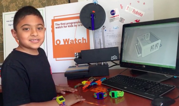
Omkar is a special 8 years old who created a wearable device called O Watch: an Arduino Zero-based smartwatch kit for kids. The project, recently kickstarted, allows young people to learn programming, 3D printing and a bit of craft while making their own smartwatch and customizing it. The kit will be released with a series of learning tools including a kid-friendly website with easy tutorials, examples and a community to share creations.
He’s not new to DIY tech and learning as he’s been doing a few workshops to teach Arduino to other kids and likes it when they get excited about making Arduino projects. Omkar told us:
I was first interested in robots. But my dad got me started with projects that light up LEDs that were easier to learn and code myself. (ps: my dad did not let me get a robot kit at first :).
I decided to do a wearable project because there were many of them I saw in the news and I thought they were cool. I wanted to make a smartwatch so that I could wear it myself and share my project with my friends in school.
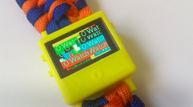
If you are a kid and are new to making, O Watch could be a great starting point as you’ll learn about coding, 3d printing, craft and also sharing. The Arduino IDE will be your primary programming tool for the watch, the case can be 3D printed in a color of your choice and you’ll experiment on how to knot yourself a cool band to wear it.
What are you waiting for? You have just a few days to back the project on Kickstarter and have an O Watch delivered to your home!
We are excited to introduce our new collaboration with Autodesk, launching with us the Arduino Basic Kit in the US! Starting today we are bringing creativity and electronics to everyone wanting to get started with more than 30 components added into the 123D Circuits simulator and 15 step-by-step tutorials available through the Project Ignite learning platform.
With the Arduino Basic Kit you’ll be able to access digital simulations for a unique experience of engagement with the kit, understanding and tapping right away into the power of smart objects.
“Arduino is creating new opportunities for makers and educators to get hands on with coding and electronics,” said Samir Hanna, vice president and general manager, Consumer and 3D Printing, Autodesk. “Our collaboration with Arduino will enable our passionate community of users to unlock their creativity while building the skills to succeed in a technologically-focused world.”
“By collaborating with Autodesk on the Arduino Basic Kit we are showing that designing electronics is a great educational area for teachers,” said Massimo Banzi, co-founder of Arduino. “By offering our tutorials in digital format instructors can involve students of all ages on interactive projects within Project Ignite platform.”
Autodesk recently launched Project Ignite during the White House National Week of Making to provide a free and open learning platform that builds the skills of young learners through creative, hands-on design experiences focused on the latest technology trends like 3D printing and electronics. Through these efforts, Autodesk aims to empower the next generation of innovators with the tools and confidently enter this new future of making things.
What’s in the Arduino Basic Kit:
All the physical and digital components you need to build simple projects and learn how to turn an idea into reality using Arduino and Autodesk 123D Circuits.
The digital simulations in 123D Circuits provide a unique experience to engage and learn about the power of smart objects .
Exclusive online access to 15 step-by-step tutorials, through the Project Ignite learning platform, to make simple projects using components that let you control the physical world.
Projects include:
Get to know your tools: An introduction to the concepts you need to know to advance
Love-O-Meter to measure how hot-blooded you are
Zoetrope to create a mechanical animation you can play forward or reverse
Every month Australian electronics magazine Silicon Chip publishes a variety of projects, and in February 1994 they published the “90 Second Digital Message Recorder” project. That was a long time ago, however you can still find the kit today at Altronics (and at the time of writing, on sale for AU$26), and thus the subject of our review.
The kit offers a simple method of recording and playing back 90 seconds of audio, captured with an electret microphone. When mounted in a suitable enclosure it will make a neat way of leaving messages or instructions for others at home.
Assembly
The kit arrives in typical Altronics fashion:
… and includes everything required including IC sockets for the ISD2590 and the audio amplifier:
The PCB missed out on silk-screening – which is a pity:
however it is from an original design from twenty years ago. The solder mask is neat and helps prevent against lazy soldering mistakes:
Finally the detailed instructions including component layout and the handy Altronics reference guide are also included. After checking and ordering the resistors, they were installed first along with the links:
If you have your own kit, there is a small error in the instructions. The resistor between the 2k2 and the 10uF electrolytic at the top of the board is 10k0 not 2k2. Moving on, these followed by the capacitors and other low-profile components:
The rest of the components went in without any fuss, and frankly it’s a very easy kit to assemble:
The required power supply is 6V, and a power switch and 4 x AA cell holder is included however were omitted for the review.
How it works
Instead of some fancy microcontrollers, the kit uses an ISD2590P single chip voice recording and playback IC:
It’s a neat part that takes care of most of the required functions including microphone preamp, automatic gain control, and an EEPROM to store the analogue voltage levels that make up the voice sample. The ISD2590 samples audio at 5.3 kHz which isn’t CD quality, but enough for its intended purpose.
Apart from some passive components for power filtering, controls and a speaker amplifier there isn’t much else to say. Download the ISD2590 data sheet (pdf), which is incredibly detailed including some example circuits.
Operation
Once you apply power it’s a simple matter of setting the toggle switch on the PCB down for record, or up for playback. You can record in more than one session, and each session is recorded in order until the memory is full. Then the sounds can be played back without any fuss.
The kit is supplied with the generic 0.25W speaker which is perhaps a little weak for the amplifier circuit in the kit, however by turning down the volume a little the sound is adequate. In this video you can see (and hear) a quick recording and playback session.
Conclusion
This kit could be the base for convenient message system – and much more interesting than just scribbling notes for each other. Or you could built it into a toy and have it play various tunes or speech to amuse children. And for the price it’s great value to experiment with an ISD2590 – just use an IC socket. Or just have some fun – we did. Full-sized images are available on flickr.
And if you enjoyed this article, or want to introduce someone else to the interesting world of Arduino – check out my book (now in a third printing!) “Arduino Workshop”.
Have fun and keep checking into tronixstuff.com. Why not follow things on twitter, Google+, subscribe for email updates or RSS using the links on the right-hand column, or join our forum – dedicated to the projects and related items on this website. Sign up – it’s free, helpful to each other – and we can all learn something.
In this review of an older kit we examine the aptly-named “Mini Stereo Amplifier” from Dick Smith Electronics (catalogue number K5008), based on the article published in the October 1992 issue of Silicon Chip magazine.
The purpose of the kit is to offer a stereo 1W+1W amplifier for use with portable audio devices that only used headphones, such as the typical portable tape players or newly available portable CD players. I feel old just writing that. At the time it would have been quite a useful kit, paired with some inexpensive speakers the end user would have a neat and portable sound solution. So let’s get started.
Assembly
Larger kits like this one that couldn’t be retailed on hanger cards shipped in corrugated cardboard boxes that were glued shut. They looked good but as soon as a sneaky customer tore one open “to have a look” it was ruined and hard to sell:
The amplifier kit was from the time when DSE still cared about kits, so you received the sixteen page “Guide to Kit Construction” plus the kit instructions, nasty red disclaimer sheet, feedback card, plus all the required components and the obligatory coil of solder that was usually rubbish:
However the completeness of the kit is outstanding, everything is included for completion including an enclosure and handy front panel sticker:
… all the sockets, plenty of jumper wire and even the rubber feet:
The PCB is from the old-school of design – without any silk-screening or solder mask:
However the instructions are quite clear so you can figure out the component placement easily. Which brings us to that point – all the components went in with ease:
… then it was a matter of wiring in the sockets, volume potentiometer and power switch:
Instead of using a 3.5mm phono socket for power input, I used a 9V battery snap instead. The amplifier can run on voltages down to 1.8V so it will do for the limited use I have in mind for the amplifier. However in the excitement of assembly I forgot the power switch:
However it wasn’t any effort to rectify that. You will also notice three links on the PCB, which I fitted instead of making coils (more on this later). So at that point the soldering work is finished:
Now to drill out the holes on the faceplate. Instead of tapering out the slots on the side of the housing, I just drilled all the holes on the front panel:
Turns out the adhesive on the front panel sticker had lost its mojo, so I might head off and get some white-on-black tape for the label maker. However in the meanwhile we have one finished mini stereo amplifier, which reminds me of an old grade seven electronics project:
How it works
The amplifier is based on the STMicro TDA2822M (data sheet .pdf) dual low-voltage amplifier IC. In fact the circuit is a slight modification of the stereo example in the data sheet. As mentioned earlier, the benefit of this IC is that it can operate on voltates down to 1.8V, however to reach the maximum power output of 1W per channel into 8Ω loads you need a 9V supply. The output will drop to around 300 mW at 6V.
Finally the Silicon Chip design calls for a triplet of coils, one each on the stereo input wires – used to prevent the RF signal being “shunted away” from the amplifier inputs. The idea behind that was some portable radios used the headphones as an antenna, however we’ll use it with the audio out from a mobile phone so it was easier to skip hand-winding the coils and just put links in the PCB.
Using the Amplifier
The purpose of this kit was to have some sound while working in the garage, so I’ve fitted a pair of cheap 1W 8Ω speakers each to a length of wire and a 3.5mm plug as shown in the image above. And for that purpose, it works very well.
Conclusion
Another kit review over. This is a genuinely useful kit and a real shame you can’t buy one today. And again – to those who have been asking me privately, no I don’t have a secret line to some underground warehouse of old kits – just keep an eye out on ebay as they pop up now and again. Full-sized images and much more information about the kit are available on flickr.
And while you’re here – are you interested in Arduino? Check out my new book “Arduino Workshop” from No Starch Press.
In the meanwhile have fun and keep checking into tronixstuff.com. Why not follow things on twitter, Google+, subscribe for email updates or RSS using the links on the right-hand column? And join our friendly Google Group – dedicated to the projects and related items on this website. Sign up – it’s free, helpful to each other – and we can all learn something.
Planet Arduino is, or at the moment is wishing to become, an aggregation of public weblogs from around the world written by people who develop, play, think on Arduino platform and his son. The opinions expressed in those weblogs and hence this aggregation are those of the original authors. Entries on this page are owned by their authors. We do not edit, endorse or vouch for the contents of individual posts. For more information about Arduino please visit www.arduino.cc
You are currently browsing the archives for the kit category.