Posts | Comments

Planet Arduino

Archive for the ‘save money’ Category

Jun
16

Hello readers

Instead of a normal day involving fun and learning with electronics, I got the scare of my life and a very sore back. You’re probably thinking it was something to do with the bedroom, but (un)fortunately no. It was revenge of the cheap plug pack. (In Australia we call wall warts plug packs).

In the recent past I wrote about a couple of cheap plug packs from eBay – here. Foolishly I kept using the other working plug pack. Not any more!

Consider this photo:

Notice how there is the adaptor with the Australia pins – this slides on and off relatively easily. Today I went to unplug the whole thing, by gripping the small adaptor which would pull the lot out at once. However my grip was not strong enough and my fingers slipped, pushed down and pulled at the plugpack itself – just enough to leave a gap and the pins exposed. (see below) At which point my fingers slipped and grabbed the live pins.

Although I consider myself to be a large physical specimen (185cm tall, 120kg) the shock was amazing (in a bad way). I fell arse over and ended up flat on the floor, and some strange feelings in my chest. After a few moments I sat up and had a walk around. Luckily my doctor is only ten minutes walk away so she gave me a once-over and told me to relax for the rest of the day.

So – the morals of today’s story:

One – don’t cut corners on safety by using substandard equipment

Two – no matter how familiar you are with electronics or electrical work – ELECTRICITY CAN KILL YOU!

Three – always see a doctor, even for the slightest shock.

If you have a tale of woe to share, please leave a comment below or in our Google Group.

As always, thank you for reading and I look forward to your comments and so on. Please subscribe using one of the methods at the top-right of this web page to receive updates on new posts.

Otherwise, have fun, be good to each other, stay safe – and make something! :)


Hello readers

Today you can follow making a simple 5V DC power supply from initial idea to finished product. This is not an exercise in making a flash power supply, just solving a problem with the parts at hand.

When writing my Arduino tutorials, or generally experimenting with the breadboards – and more often both – I have needed 5V DC to power something, or in the case of working with two Arduinos at once, having to run USB cables all around the place just to power them. Some may say “Oh, just get another couple of wall warts/plug packs”. True, but good ones are over Au$20 here… and buying cheap ones have not been so successful in the past. However, I do have a collection of odd-voltage plug packs from old cordless phones and so on.. 12V AC, 15V DC etc. And to be honest, right now the bbbooost project is in pieces in a box as I’ve run out of breadboards at the moment working on other things.

So while at my desk I thought “How can I combine my need for 5V, my cheapness and use one of these plugpacks?”. Easy!

After perusing my stock database it turned out that all the parts were already around me to make a simple 5V supply using an LM7805 voltage regulator. It is quite versatile, can accept voltages up to 35V, and I have some in the drawer. Here is the data sheet: LM7805.pdf.

Following this it occurred to me that it would be nice to not have to worry about the type of current from the plug pack – AC or DC. So my circuit needs a bridge rectifier. That can be made with four 1N4004 diodes. And it would be nice to have a power-on indicator that isn’t a tiny speck of light. Thankfully I bought some 20mm red LEDs when Farnell had a crazy sale last year. Perfect.

And finally, a nice enclosure. Or anything really, to hold it all together. A small semi-opaque jiffy box was hiding in the cupboard with some veroboard, so they will be used. How? Here is my schematic: (click to enlarge)

Oh – the resistor is 560 ohms. And here are the participants in this project:

The black stuff at the top-right is heatshrink. The next though was how to mount the board in the box – I don’t have any standoffs, but the box does have some slots to hold the board. So this tells me how much space there is to use on the board, as I will trim it down to fit the space available:

But before hacking things up with the tinsnips, it pays to see if your circuit will actually fit in the board space available. (However my circuit was quite small, so I knew it would fit). This can be done by laying out your parts on a sheet of paper that has a grid of dots at 2.54mm intervals. Next was to measure the internal dimensions of the box in order to cut the veroboard. Then out with the tinsnips and chop chop chop. When using tinsnips or a saw of some sort, try and cut a little outside of the line – as the PCB material does flex a little .This means that you may lose 2~3 mm at the edges, so make allowances for that.

Moving on, I now have the board sized for the box and can start component placement:

The parts just fit in together nicely. I will have to drill the holes for the 7805 regulator so it can fit, however it doesn’t really leave room for the 0.1uF capacitor. However it is not really necessary, the output will be ok without it. The leads from the power socket, and to the switch and output lead will feed from the bottom of the PCB.

Now for one final visual check, and then to solder in the components.

After doing so, then it was time to put the link in and cut the tracks. I use a sanding bit on the drill to cut the tracks, completely removing the copper. :)

After cutting the tracks on the solder side, it was a good time to use the continuity function of the multimeter to check for shorts between tracks and other errors. The soldering proved to be fine, and the track cuts worked. Now it was time to position the DC socket and switch in order to wire them in, then drill their holes. The output wire is to come out of the top:

Now all there is to do is solder the connecting wires from the DC socket to the rear of the circuit board, and the output wire via the switch. At this point the unit was also tested. Naturally my eyesight had failed me and a short had appeared. However it was sorted out with the solder sucker:

Notice how I tied a know in the output lead before it passes through the lid – this is to stop accidental damage to the board caused by someone pulling the wire out. Here is the finished product, with a nice red glow for a power-available indicator:

Hooray – finished. What else was there to do on a Tuesday night? The LED indicates power is supplied to the box, and the switch just controls the load. Not too happy about that 5.05V reading… but then again, that meter was somewhat inexpensive.

I hope you enjoyed peering into my electronic life once again. The purpose of this post was more of a confidence-builder than anything, but hopefully someone out there read this and thought “Yes, I can do that”. So go for it!

As always, thank you for reading and I look forward to your comments and so on. Furthermore, don’t be shy in pointing out errors or places that could use improvement. Please subscribe using one of the methods at the top-right of this web page to receive updates on new posts. Or join our new Google Group. High resolution images can be found on flickr.

Otherwise, have fun, be good to each other – and make something! :)


Hello fellow Arduidans

Today we are going to make a real time clock Arduino shield. If you have been following my tutorials,  in weeks 7, 8 and onwards we have been making use of the Maxim DS1307 real time clock chip. Although it is a very interesting part to use, implementing it has not been so easy, therefore the reason for this shield. So let’s go!

First of all, we need create our circuit diagram. Thankfully the Maxim DS1307 data sheet [pdf] has this basics laid out on page one. From examining a DS1307 board used in the past, the pull-up resistors used were 10k ohm metal films, so I’m sticking with that value. The crystal to use is 32.768 kHz, and thankfully Maxim have written about that as well in their application notes [pdf], even specifying which model to use. Phew!

So here is the circuit diagram we will follow (click on it to enlarge):

Which gives us the following shopping list:

  • One arduino protoshield pack. I like the yellow ones from Freetronics, however others may prefer this one
  • X1 – 32.768 kHz crystal – Citizen America part CFS206. You should probably order a few of these, I broke my first one very quickly…
  • IC1 – Maxim DS1307 real time clock IC
  • 8-pin IC socket
  • CR2032 3v battery
  • CR2032 PCB mount socket
  • R1~R3 – 10k ohm metal film resistors
  • C1 – 0.1 uF ceramic capacitor

And here are our parts, ready for action:

The first thing to do is create the circuit on a solderless breadboard. It is much easier to troubleshoot possible issues before soldering the circuit together. Here is the messy test:

Messy or not, it worked. Instead of writing another sketch, the example 7.3 from arduino tutorial seven was used. Here is a copy: example 7.3.pdf.

The next step is to consider the component placement and wiring for the protoshield. Try not to rush this step, and triple-check your layout against the schematic. As my protoshield has a green and red LED as well, I have wired the square-wave output to the green LED. You can never have too many blinking lights…

At this point I celebrated the union of tea and a biscuit. After returning to the desk, I checked the layout once more, and planned the solder bridges. All set – it was time to solder up. If you have the battery in the holder for some reason, you should remove it now, as they do not like getting warm. Furthermore, that crystal is very fragile, so please solder it in quickly.

And here we are – all soldering done except for the header sockets. At this point I used the continuity function of the multimeter to check the solder joints and make sure nothing was wrong with the circuit.

Final checks passed, so on with the headers. To make this easier, I stick some header pins in the sockets, then place the whole lot in a solderless breadboard to keep it straight. Well, it works for me:

Just a side note – always make sure you have enough consumables, the right tools, etc., before you start a project. This is how much solder I had left afterwards…

Moving on … in with the battery and the DS1307 –  we’re done!

It is now time for the moment of truth – to insert the USB cable and re-run the sketch… and it worked! The blinking LED was too bright for me, so I de-soldered the wire. If you are making a shield, congratulations to you if yours worked as well. If it did not, don’t be afraid to hit me up via email or our Google Group with your questions. Note that if you are using this shield, you cannot use analog pins 4 and 5 – they are being used as the I2C bus. Time to clear up the desk and wash my hands.

Now to put this shield to work. Last week we made an LCD module shield – so let’s pile up the shields and make a digital clock. We can re-use the sketch from arduino tutorial example 7.4, with the liquidcrystal() corrected to use the LCD shield pins. Here is the modified sketch: ds1307shielddemo.pdf.

And my post wouldn’t be complete without a video, so here are our new shields in action!

So there we have it. Another useful shield, and proof that the Arduino system makes learning easy and fun. High resolution photos are available on flickr. If you have any questions or comments, please leave them below, or consider joining our Google Group!

As always, thank you for reading and I look forward to your comments and so on. Please subscribe using one of the methods at the top-right of this web page to receive updates on new posts!


May
20

Hello fellow Arduidans

Today we are going to make an Arduino shield with an LCD module. More often than not I have needed to use an LCD shield in one of my projects, or with the Arduino tutorials. Sometimes I would use the Electronic Brick parts, which in themselves are a great product, but the chassis blocks some of the pins that we need to use. So instead of complaining, we’re doing something about it.

Before we start, let me say this: “to fail to plan is to plan to fail”.  That saying is very appropriate when it comes to making your own shields.

The first step is to gather all of the parts you will need. In this case:

  • an LCD module (backlit if possible, but I’m being cheap and using a non-backlit module)
  • a 10k linear trimpot, used to adjust the LCD contrast
  • a blank protoshield that matches your Arduino board (Duemilanove or Mega)
  • various header pins required to solder into the shield (they should be included with your protoshield)
  • plenty of paper to draw on

For example:

Next, test your parts to ensure everything works. So, draw a schematic so you have something to follow:

And then build the circuit on a solderless breadboard, so you can iron out all the hardware bugs before permanently soldering into the shield. If you have a backlit LCD, pins 15 and 15 are also used, 15 for backlight supply voltage (check your data sheet!) and 16 for backlight ground:

In this example, I wrote a simple sketch to send some random numbers to the LCD. (Very similar to tutorial example 2.2) Excellent, everything is working as it should.

Now to make the transition from temporary to permanent. Place your components onto the protoshield, and get a feel for how they can sit together. Whilst doing this, take into account that you will have to solder some jumper wires between the various pads and the digital pin contacts and the 5V strip at the top row, as well as the GND strip on the bottom row. You may find that you have to solder jumper wires on the bottom of the shield – that’s fine, but you need to ensure that they won’t interfere with the surface of your Arduino board as well.

Furthermore, some protoshields have extra functions already added to the board. For example, the shield I am using has two LEDs and a switch, so I will need to consider wiring them up as well – if something is there, you shouldn’t waste the opportunity to not use them.

If your shield has a solder mask on the rear, a great way to plan your wiring is to just draw them out with a whiteboard marker:


Remember to solder these wires in *before* the LCD … otherwise you will be in a whole world of pain. The LCD should be soldered in second-last, as it is the most difficult thing to desolder if you have made any mistakes. The last items to solder will be the header pins. So let’s get soldering…

After every solder joint, I pushed in the LCD module – in order to check my placement. You can never check too many times, even doing so I made a small mistake. Having a magnifying glass handy is also a great idea:

Now just to soldier on, soldering one pad at a time, then checking the joint and its relationship with where it should be on the board. Be very careful when applying solder to the pads, they can act as a “drain” and let lots of solder flow into the other side. If this happens you will spend some time trying to remove that excess solder – a solder sucker and some solder wick is useful for this.

Finally all the wires and pads were connected, and I checked the map once more. Soldering in the LCD was  the easiest part – but it is always the most difficult to remove – so triple check your work before installing the display. Now it was time to sit in the header sockets, and test fit the shield into my arduino board. This is done to make sure there is sufficient space between the wires on the bottom of our shield and the top of the arduino:

Even though you wouldn’t normally put a shield on top of this shield, I used the header sockets to allow access to all of the arduino pins just in case. Soldering the sockets was easy, I used blu-tack to hold them into place. Crude but effective.

And we’re finished. Soldering is not the best of my skills, so I checked continuity between the pins on the LCD and where they were supposed to go, and also electrically checked for bridges between all the soldered pins to check for shorts. A multimeter with a continuity buzzer makes this easy. Naturally I had a short between LCD pin 14 and 13, but some solder wick helped me fix that.

So electrically it was correct… time to see if it actually worked! At this point it is a good idea to clear up the workspace, switch off the soldering iron, put it somewhere safe to cool down, then wash your hands thoroughly.

Here are some photos of the finished product on my arduino board:

The only thing to do was alter the demonstration sketch to take account for the pin placements, and insert some code to blink the LEDs. For example: LCDshielddemo.pdf. I never need an excuse to make a video clip, so here is the result:

So there you have it. With a little planning and care, you too can make your own Arduino shield. An LCD shield would be useful for everyone, as they are great for displaying data and requesting input, yet quite fiddly to use with a solderless breadboard. High resolution photos are available on flickr.

If you have any questions or comments, please leave them below, or consider joining our Google Group!

As always, thank you for reading and I look forward to your comments and so on. Please subscribe using one of the methods at the top-right of this web page to receive updates on new posts!


An oscilloscope.

[update: usage photos 12/05/2010]

Since returning to the world of electronics and general gadgetry, an oscilloscope has always been on my shopping list. However, they are not cheap. Sure, I could get a second-hand one from eBay, but here in Australia there are not that many floating around; the used ‘scopes are generally ex-defence or education and looked pretty whipped. However, being an impatient person a kit from JYETech (the same people who make the capacitance meter kit I reviewed in March) really grabbed my imagination – a kit digital oscilloscope! Cheap, low specification, but interesting nevertheless. After thinking about it too much, and after watching all the youtube videos about it… I ordered one.

Let’s see what happens…

After a week my parcel arrived. Once again JYE Tech have not spared any expense on the packaging for the actual kit, just enough for everything to be safe.

The kit has some nice panels, front and rear, and a great solder-masked, silkscreened PCB. Thankfully I ordered the version that had the SMD components already soldered. (This kit is available in three versions: full kit, SMD soldered, and totally assembled [not really a kit...!]).

And time to check all the pieces have been included. There is no list inclued, so you have to check off against the BOM from the JYE Tech website for your particular version of the kit. This is not a kit you can just jump into and solder…

The instructions are very… sparse, confusing and time-consuming. One double-sided A4 piece of paper, one side with the schematic, and the other with a “quick reference”, internet links to support and a photo of the populated PCB. Thankfully, the JYETech website has all the documentation ready for download, and they also run a very well supported Google Group. Phew. They even publish the .dxf CAD files. So after downloading and printing off all of the documentation, it was time to review it and have lunch.

There is an amusing line in the instructions – “you will probably need to make a simple probe”. Yes, indeed. Included are enough parts to make a simple probe – with alligator clips at the end. Let’s call them semi-useful. They will do for the meanwhile, however a real probe set will be ordered shortly.

Anyhow, enough preparation and reading. Time to build. NOTE: There are several versions of this kit – please double-check you have the correct assembly instructions. Look at your PCB – there is a white sticker on the edge with a code such as “06202KP…”  - make sure that you have the correct sheet for your kit. There is no guarantee the correct sheet will ship with the meter!

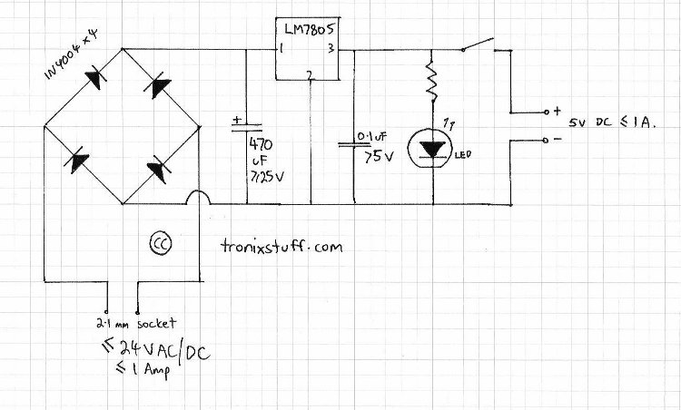
Thankfully due to the SMD nature of most of the parts, there isn’t that much to solder. Firstly, I wanted to get the 7805 regulator and heatsink in:

… and the rest of the parts – 7 capacitors, a diode and an inductor. You really need to have your wits about you – there are places on the PCB and parts in the schematic for which you are not to use – it is easy to get lost if you don’t concentrate. Just remember to match the physical components supplied against the BOM from the website, and only install those – after considering the assembly instructions. Another caveat is that you need to check you have the correct documentation for your PCB. For example, mine was a 06202KP, whereas the website had something different. Thankfully the Google Group had the correct .pdf file.

Remember that positive pins of capacitors into square pads. There seems to be an ambiguity in the instructions regarding C14 – for the 06202 model, C14 positive is on the right hand side.

Next, the sockets for signal and DC, switches and push buttons. You need to get the switches and buttons flush with the PCB, otherwise you will have issues with the top panel and button caps.

Don’t forget the 2×4 pin header – solder it in before the LCD! Now for the LCD.

Stop now. Make sure you run the power tests as per the assembly instructions. Once that LCD is soldered in, having to take it out again will be a huge PITA.

When you look at the rear of the LCD module, there are two rows of 20 holes – solder the row of pins into the row with markings (GND~NC). I found the easiest way to do this was to sit the row of pins into the main PCB, sit the LCD on top and solder the pins into the LCD module. The solder in the 2 pairs of pins that support the LCD. You may find the heatsink blocks one of the pins – just cut one pin off and use that then.

Now it is seven hours later. To cut a long story short – be very careful when soldering the LCD pins. It is very easy to cause a bridge which will wreak havoc and short out something, which cooks the LCD, 7805 and the microprocessor. If your unit heats up like a stove, unplug it and triple check your soldering under a magnifying glass. Run continuity tests to be sure you haven’t shorted out anything.

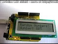
But thankfully – after all my time working on it, hunched over a hot iron in a dark room, and staring through a magnifying glass:

Woohoo! We have life!

I had that heatsink on just in case  - didn’t take it off for the photo. Now it is time to assemble the body and make it look presentable:

And of course … I’ll need a set of probes. So I assembled them using the parts included in the kit. They will have to do until my real one arrives.

Finally – I can clean up the desk and wash my hands. Originally I was going to write a whole section explaining how oscilloscopes work and the terminology. But thankfully the good people at Tektronix have done this already and made a nice little e-book for us. So here it is: XYZs of Oscilloscopes (Tektronix) PDF.

Now, let’s spend some time examining what this baby can do. Just a note at this point, if you didn’t install the heatsink, you should install a clip-on heatsink over the 7805. After sitting on my desk for around 30 minutes the 7805 does get warm.

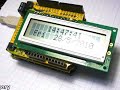
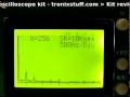
[update] Here are some photos of the scope in use:

14.2 volts AC. The scope should have displayed the minimum and maximum, but for some reason has clipped them.

In order to see half of the full wave, the V.POS was lowered to the minimum. This is indicated by the tiny marker at the bottom left of the LCD

Again with V.POS at the minimum, the time period was altered, and the display frozen to see the maximum.

5 volts DC at 5 volts per division

5 volts DC at 2 volts per division

By dropping V.POS to the minimum, you can increase the maximum amplitude possible. Note the tiny marker at the bottom-left of the screen, indicating the new 0V line.

5 volts DC using 1 volt per division.

2 volts DC at 0.5 volts per division (using x5 and 0.1 settings)

1.25 volts DC at 0.5 volts per division

By default it shows 50Hz as that is the frequency of mains voltage in Australia (probes not connected, it gets the default frequency through the power supply [Australia is 240V 50 Hz]).

And now for a video, a short compilation of various measurements: DC voltage, frequency, FFT and pulse-width modulation.

You can also upgrade the firmware and save screen shots if you attach a cable to the jumpers on the rear of the main PCB. If you were to do this often enough, it would be wise to cut a rectangle out of the back panel.

Conclusion.

To be honest, I found this kit very challenging to assemble, finding the correct instructions the second time around was very frustrating, and the documentation is very poor. This is not a kit for beginners, more of a curiosity for those experienced in electronics work and fault-finding. In saying that, I’m glad I had a go – assembling and getting it to work taught me a lot about my own abilities, fault-finding, and tested my patience. But it gave me a real buzz once I got it working.

It was rather annoying to use such a low screen resolution, you won’t be detecting too much ripple on your DC power supplies with this one. But for the price, it is an interesting piece of gear. I will probably end up giving it away as a prize or something. It has a maximum of 50 volts peak to peak input amplitude, but I couldn’t for the life of me hone the display down to show 12 volts AC without cutting off the minimum and maximum. Will persevere and spend more time with it.

Furthermore, it is a good stepping stone to acquiring a full oscilloscope – if you find yourself using this one and getting frustrated with the limitations, it’s time you bought a full ‘scope!

This kit is available from a variety of sources, and Little Bird Electronics has all three variants available in stock.

Thank you for reading and I look forward to your comments and so on. High resolution photos are available on flickr.

Please subscribe (see the top right of this page) to receive notifications of new articles. If you have any questions at all please leave a comment (below).

[Note - this kit was purchased by myself personally and reviewed without notifying the manufacturer or retailer]

May
02

Greeting again to followers of the bbboost journey. It has been a month since the last instalment, however the 20V DC plug pack took a long time to arrive from the land of China. Nevertheless, the project is moving forward. For my new readers, the bbboost is a power supply that can be assembled by a beginner, and can offer a smooth variable DC output voltage of between ~1.8 and ~20 volts – perfect for experimenting, breadboard, and generally saving money by not buying batteries. You can just make a PCB version, or mount it in an enclosure like a professional desktop unit. No mains voltage wiring is required, so it will fine for the younger enthusiasts. Follow the project from here.

This time I have breadboarded the power supply module, using the circuit described in chapter two.  Let’s have a bit of a look:

These trimpots were ok, but it would be preferable to use the fully enclosed dustproof versions. Will order some and try ‘em out.

One trimpot (the blue and white one) is 5k ohm, – to adjust between the full range, so this is the ‘coarse’ adjuster; the other trimpot is only 500 ohms and changes the voltage selected by the coarse pot by around +/- 1.2 volts. The purpose of having two controls is to make it very easy to select your required voltage down to one-hundredth of a volt. The following video clip is a rough example of this type of adjustment in action:

This power supply will also be designed for installation into a nice enclosure, so in that case one would use normal-sized potentiometers for the coarse and fine voltage adjustment. Will try that for the next instalment.

So,  thank you once more for reading. Please leave feedback and constructive criticism or comments at your leisure… and to keep track, subscribe using the services at the top right of this page!


  • Newsletter

    Sign up for the PlanetArduino Newsletter, which delivers the most popular articles via e-mail to your inbox every week. Just fill in the information below and submit.

  • Like Us on Facebook