Watching video on computers used various methodologies in correlation with the power of computer microprocessors. Animated GIF led to MJPEG video, then came MPEG-1 video, best known for video CD (VCD) recording. When processors became more powerful, MPEG-2 was developed and used for DVDs etc. Later, MPEG-4 was possible with yet faster processors.
The same progression is happening with small devices built using microcontrollers. Animated GIFs have been available for the last year. MJPEG has been demonstrated.
Now 陳亮手痕定律 (@moononournation on X/Twitter) has been coding an MPEG-1 player in Arduino for the LilyGo T-Keyboard Blackberry lookalike. Video quality is pretty good for the low resolutions involved.
Like many of you, we’ve been keeping a close eye on the CH32 family of RISC-V microcontrollers from WCH Electronics. You can get the CH32V003, featuring 2 kB RAM and 16 kB of flash for under fifteen cents, and the higher-end models include impressive features like onboard Ethernet. But while the hardware is definitely interesting, the software side of things has been a little rocky compared to what we’ve come to expect from modern MCUs.
Things should start looking up a bit though with the release of an Arduino core for the CH32 direct from WCH themselves. It’s been tested on Windows, Linux, and Mac, and supports the CH32V00x, CH32V10x, CH32V20x, CH32V30x, and CH32X035 chips. Getting it installed is as easy as adding the URL to the Arduino IDE’s Boards Manager interface, though as the video below shows, running it on Linux does require an extra step or two.
So far, we’ve seen several projects, like this temperature sensor or this holiday gizmo that use [cnlohr]’s open-source toolchain. But there’s no question that plenty of hobbyists out there feel more comfortable in the Arduino environment, and if those folks are now able to pick up a CH32 and do something cool, that means more people jumping on board, more libraries developed, more demo code written…you get the idea.
Just like the ESP8266’s popularity exploded when it was added to the Arduino IDE, we’ve got high hopes for the CH32 family in the coming months.
[Trent M. Wyatt]’s CPUVolt library provides a fast way to measure voltage using no external components, and no I/O pin. It only applies to certain microcontrollers, but he provides example Arduino code showing how handy this can be for battery-powered projects.
The usual way to measure VCC is simple, but has shortcomings.
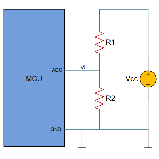
The classical way to measure a system’s voltage is to connect one of your MCU’s ADC pins to a voltage divider made from a couple resistors. A simple calculation yields a reading of the system’s voltage, but this approach has two disadvantages: one is that it constantly consumes power, and the other is that it ties up a pin that you might want to use for something else.
There are ways to mitigate these issues, but it would be best to avoid them entirely. Microchip application note 2447 describes a method of doing exactly that, and that’s precisely what [Trent]’s Arduino library implements.
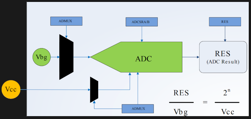
What happens in this method is one selects Vbg (a fixed internal voltage reference that is temperature-independent) as Vin, and selects Vcc as the ADC’s voltage reference. This is essentially backwards from how the ADC is normally used, but it requires no external hookup and is only a bit of calculation away from determining Vcc in millivolts. There is some non-linearity in the results, but for the purposes of measuring battery power in a system or deciding when to send a “low battery” signal, it’s an attractive solution.
Being an Arduino library, CPUVolt makes this idea very easy to use, but the concept and method is actually something we have seen before. If you’re interested in the low-level details, then check out our earlier coverage which goes into some detail on exactly what is going on, using an ATtiny84.
Making conference badges, official or unofficial, has become an art form. It can get pretty serious. #badgelife.
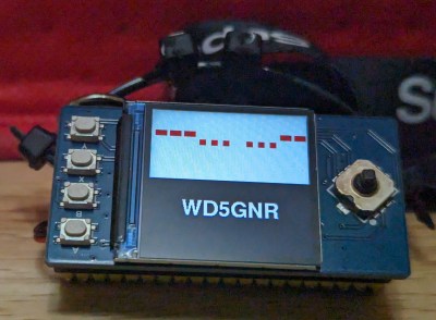
But DEFCON-goers aren’t the only people making fancy personalized nametags. Hams often had callsign badges going back as far as I can remember. Most were made of engraved plastic, but, at some point, it became common to put something like a flashing LED on the top of the engraved antenna tower or maybe something blinking Morse code.
Going back to that simpler time, I wanted to see if I could make my own badge out of easily accessible modules. How easy can it be? Let’s find out. Along the way, we’ll talk about multicore programming, critical sections, namespaces, and jamming images into C++ code. I’ll also show you how to hijack the C preprocessor to create a little scripting language to make the badge easier to configure.
Bottom Line Up Front
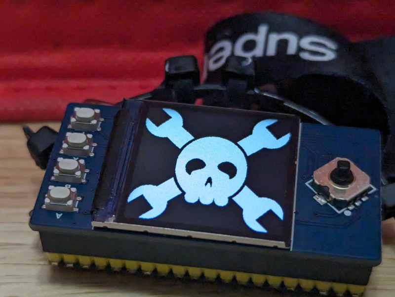
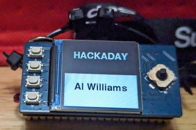
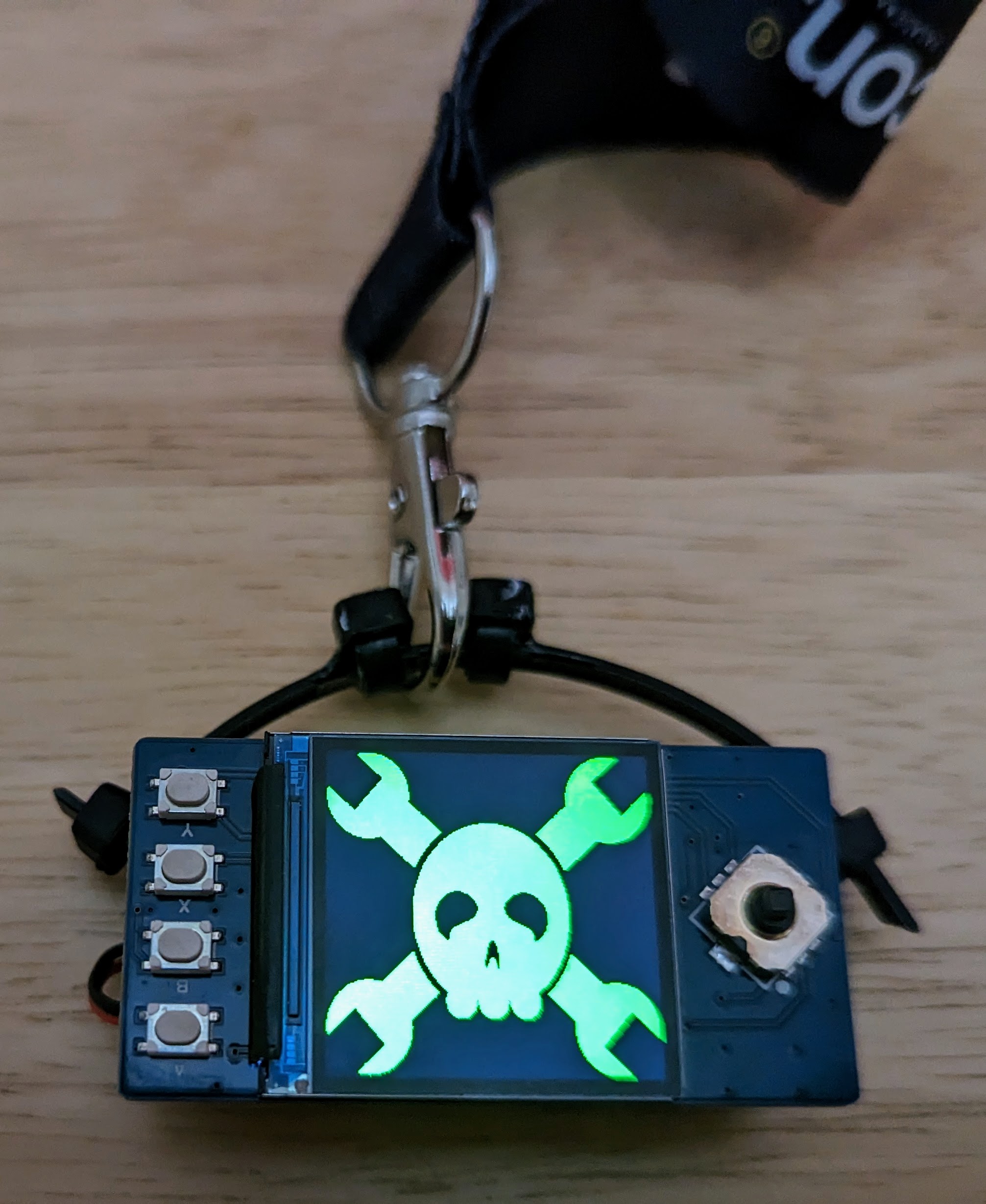
The photo shows the Pico badge. It has an RP2040 CPU but not a proper Raspberry Pi Pico. The Waveshare RP2040-Plus clone has a battery connector and charger. It also has a reset button, and this one has 16 MB of flash, but you don’t need that much. The LCD is also a Waveshare product. (This just happened to work out. I bought all of this stuff, and I don’t even know anyone at Waveshare.) The only other thing you need is a USB C cable and a battery with an MX 1.25 connector on it with the correct polarity. Hardware done! Time for software.
For the software, you have a lot of options. The Waveshare documentation shows you how to drive the display using standard C code and Micropython. I decided to go a different way and stick with the Arduino tools. [Earlephilhower] has a fantastic board support package for the RP2040. I’ve been using it lately with excellent results. It has a lot of great things baked in, including straightforward support for multicore and more.
The badge is more or less a slide show. You can display images and write text either on a solid background or over an image. Each slide appears for a set amount of time although, within limits, you can speed it up or slow it down. You can see a quick demo in the video below.
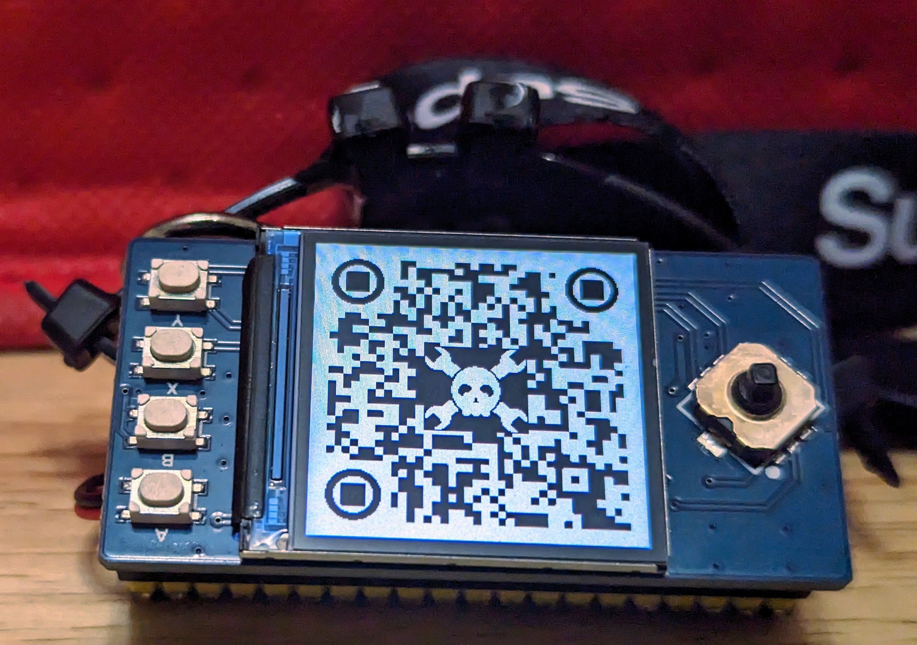
The badge can send you to its own GitHub page
Obviously, if you want to customize it, you could grab my code and change it. But that means you need to understand a little about it. Who has time for that? Instead, the code can take a script file that — eventually — turns into C code, but you don’t have to know much about the internals of the badge.
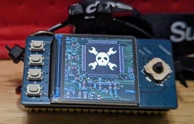
For example, suppose you want to show a jolly wrencher with your name written across it. The script looks like this:
There are commands to draw color and monochrome images, fill the screen with colors, and print using various fonts and colors.
The buttons respond almost instantly because they are run by the RP2040’s second core. This is probably overkill, but it is nearly effortless to do. The four buttons along the left side let you select a few scenes or loops, change the slide show timing, and pause the show.
The joystick up and down gives you finer control over the timing, while the left and right jump to different parts of the slide show. Pushing the joystick toggles the screen on or off. To customize the buttons, you need a little custom C code, but you don’t need a deep understanding of the hardware or software.
The Deets
The software only has four major parts: the display, the button interface, services to the script, and the actual script language processing. All of these are simple once you dig into them.
The graphics library I used is the Arduino GFX library. This library is impressive because it handles many different display types. You must define a bus to tell the library how to talk to the display. In this case, that’s SPI on specific pins. Then, the library itself is abstracted from the communication channel. You can easily use the screen as a text output device or a graphics output device. It even supports u8g2 fonts.
Buttons and Multicore
At first, I just checked each switch as part of the standard loop processing. Why not? But there’s a problem. The very nature of the badge means that most of the time, the processor is executing a delay between “slides.” While that was happening, the keys were not being scanned. You could, of course, break the delay into small parts simply to check the keys in between.
However, the RP2040 has two perfectly fine cores, and one of them normally stays asleep. By default, your program runs on core 0 along with the USB serial port. So why not use that extra core? Programming with multiple cores must be hard, though, right?
Actually, no. If you want two things going on simultaneously, you only have to define setup1() and loop1() in your program (see core1.cpp). This is like the standard Arduino setup and loop, but it will wake up core 1 and run on it. It is that simple.
The issue, of course, is when you want to communicate between the cores. The RP2040 support package does have a FIFO-style form of interprocess communication, but for this simple job, I went with something easier.
The two cores share one variable: button. Core 0 reads this variable and resets it to zero. Core 1 marks bits in the variable that correspond to active button pushes. It never resets the bits, so the main code will see a button push whenever it looks, even if the button was already released.
The core 1 code also has provisions for debouncing the switches and only reporting a single event to the main thread per button press. The trick is not to have both CPUs reading and writing that variable simultaneously. In a regular operating system, you’d have the idea of a critical section. In this case, I use the API call to freeze the “other” core for the brief period required to read or write the buttons variable. For example:
rp2040.idleOtherCore();
buttons |= xbtn; // put in any that are set; client will reset them
rp2040.resumeOtherCore();
I didn’t want to delay the keys too long, so the scaledelay routine (in badge.cpp) breaks the delay into 100 millisecond slices. Of course, that means delays have a practical resolution of 100 milliseconds, but that’s no big deal for this application. After each 0.1-second delay, the loop checks for any keypress, and if found, the loop exits.
Core 1 delays for 5 milliseconds in its main loop. This gives the other core a chance to run and means buttons don’t need a long press to work. Going shorter has little value, and you could probably go a little longer, which might economize on battery life.
Script Services
I wanted to provide services to the script so you could customize the badge without much effort. There is a callback function (customize) that, if provided, can do things like pause the slide show or loop it at different points.
At first, I put these functions in a static class. That way, you had to refer to them explicitly from the customize function. If your code had a function called pause, for example, it didn’t matter because you needed to call BADGE::pause to get the pause service.
After a bit, though, I realized there was no real value in having it in a static class, and a better choice would be to use a namespace. The customize code looks exactly the same either way. You still call BADGE::pause. However, now you are calling a function in the BADGE namespace, not a static function in the BADGE class. A small distinction, but handy. For example, you could do a use to import the pause function or even the whole namespace if you wanted to.
In the original code, I had static variables that were “private” to the service code. These variables are now in a nameless namespace. This is very similar to static: the code in the file can use what’s defined there, but it isn’t visible to anything else.
Compiling the Script
The script is straightforward to implement because I’ve hijacked the C preprocessor. Each script step is an element in an array of structures. Then there are C preprocessor defines that set up that array and each element (see pico-badge.h). For example, this script:
That’s it. The preprocessor does all the work of compiling. Just remember that things are set up when the array initializes. For example, the default script uses tdelay to hold the base delay between slides. Once the array builds, changing tdelay doesn’t do anything for you. You’d have to modify the item in the array, which is not much fun.
The Stag macro lets you set a numeric label (like a Basic line number) that you can later find. The numbers don’t have to be sequential — they are just to identify a position in your script. Some of the script helpers take tags so you don’t have to count (and recount) array elements to refer to a specific part of the script.
Images
If you want images, you must put them in arrays. Some websites can help with this for monochrome or color images. The GIMP can also export to .C or .H files, as seen in the video below.
If you start with the code in script.cpp, you should be able to figure out how to get it all together.
What’s Left?
Not bad for some off-the-shelf hardware. It isn’t going to win any prizes at your next conference, but you can easily customize it and make it your own. If you have one at Supercon, find me at the soldering challenge table and show off your build.
What can’t zip ties do?
I still need to produce an enclosure for the badge, although, with a 220 mAh battery wedged between the boards, it does pretty well by itself. I used a few zip ties and some super glue to make a makeshift connector for a lanyard. I wouldn’t mind putting a clock display option together, but you’d need a way to set the clock. A battery charge monitor would be nice, too.
If you could find a Pico-like CPU with both the battery charger and wireless, that would open up some possibilities. A great deal of the device capability — like PIOs and the USB port — is going to waste, too. Since the Arduino package supports LittleFS, you could read files from the “disk.” It probably ought to be able to play Life, too.
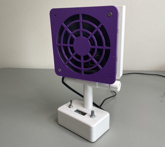
If you solder (and we know you do), you absolutely need ventilation, even for that lead-free stuff. Fortunately, [tinyboatproductions] has gotten into air quality lately and is here to help you with their snappy 3D printed air-filtering design.
At the heart of this build is a 120 mm notoriously-quiet Noctua fan coupled with a carbon filter. It does what you’d think — position the fan the right way and it sucks the air through the filter, which catches all those nasty particles.
The only problem is that the Noctua uses PWM, so there’s no governing it with a just potentiometer. To get around this, [tinyboatproductions] introduced an Arduino Nano and a buck converter, both of which were admittedly a bit overkill. Now the speed can be controlled with a pot.
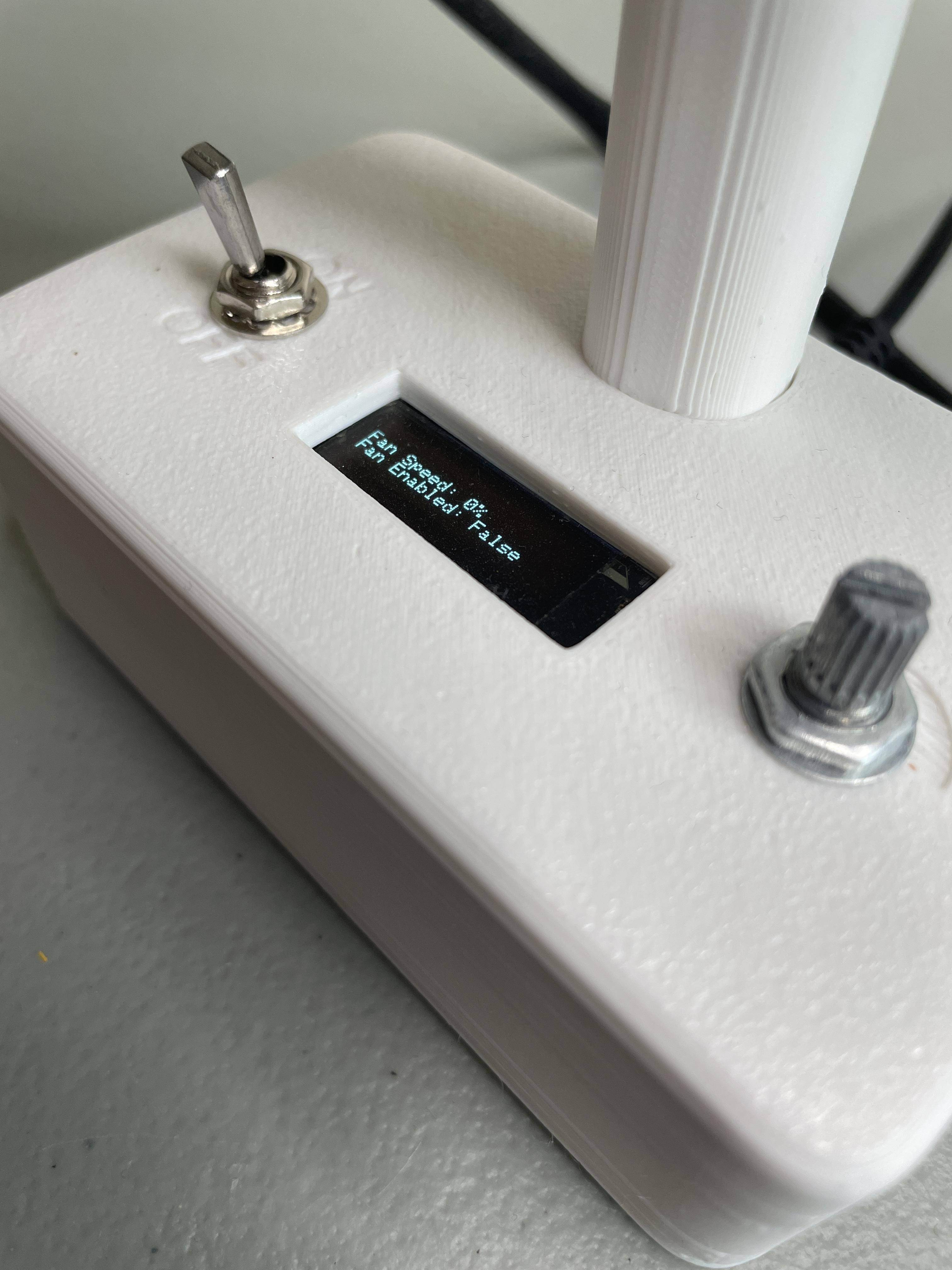
Once control of the fan was sorted, [tinyboatproductions] decide to add an OLED display to show the fan speed and power condition, which is a nice touch. Be sure to check out the build video after the break.
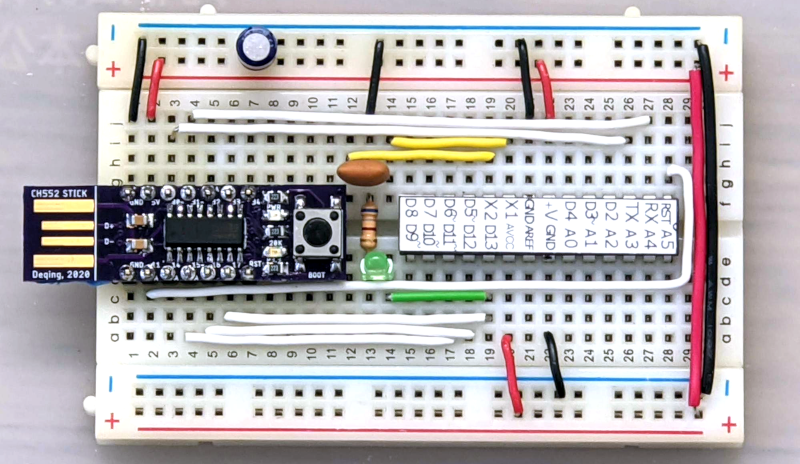
One of the things missing from the “classic” Arduino experience is debugging. That’s a shame, too, because the chips used have that capability. However, the latest IDE has the ability to work with external debuggers and if you want to get started with a classic ATMega Arduino, [deqing] shows you how to get started with a cheap CH552 8-bit USB microcontroller board as the debugging dongle.
The CH552 board in question is a good choice, primarily because it is dirt cheap. There are design files on GitHub (and the firmware), but you could probably pull the same trick with any of the available CH552 breakout boards.
There was a time when having a god-eye view of your embedded system required an expensive in-circuit emulation system. These were expensive, difficult to deploy, and rare. Then, CPUs started adding debugging hardware right on the chip. A few spare pins on the CPU and some sort of adapter would give you most of what you wanted from an emulation system. Although these adapters are often proprietary, sometimes they aren’t, or they have been reverse-engineered. If you know the protocol, it is easy enough to get a processor to speak it for you. That’s why you often see, for example, Raspberry Pi Picos debugging other Picos. There’s nothing you can’t do a million other ways here, but it is an excellent step-by-step tutorial for getting started without breaking the bank.
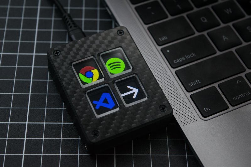
Once in a while, we see projects that could easily pass for commercial products. This is one of those projects: a (surprisingly) low-cost DIY macro pad from [Josh R] that was designed to be a cheaper alternative to the various stream decks out there. Between the carbon fiber top plate and the crystal-clear acrylic keycaps, this is quite the elegant solution.
This lovely little macro pad is built around the ESP8266, specifically the WEMOS D1 Mini V4. However, the most vital part to get right is the screen, which must be a 128 x 160 TFT display in order to line up with the 3D printed frame that divides it into fourths. Custom parts like the acrylic keycaps and the carbon fiber top plate are available on Tindie if you don’t have access to a CNC.
Operationally, Open Deck has a nice-looking GUI. Once programmed, each shortcut is capable of having three beneath it, with the fourth button reserved for Home. Be sure to check out the extremely satisfying build video after the break.
Reddit user [nomoreimfull] posted code for a dynamic WiFi beacon to r/arduino. The simple, but clever, sketch is preloaded with some rather familiar lyrics and is configured to Rickroll wireless LAN users via the broadcast SSID (service set identifier) of an ESP32 WiFi radio.
The ESP32 and its smaller sibling the ESP8266 are tiny microcontrollers that featuring built-in WiFi support. With their miniature size, price, and power consumption characteristics, they’ve become favorites for makers, hackers, and yes pranksters for a wide variety of projects. They can be easily programmed using their own SDK or through a “board support” extension to the Arduino IDE.
For the dynamic WiFi beacon, the ESP32 is placed into AP (access point) mode and broadcasts its human readable name (SSID) as configured. What makes the SSID dynamic, or rolling, is that the sketch periodically updates the SSID to a next line of text stored within the code. Of course, in the Rickroll prank this means the next line of lyrics from “Never Gonna Give You Up” by Rick Astley himself.
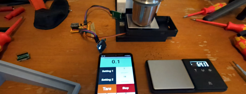
Some people take their coffee grinding seriously. So what do you do when the hot new grinders automatically weigh coffee, and yours doesn’t? Well, if you are like [Tech Dregs] and the rest of us, you hack your existing grinder, of course. The link is to the source code, but for a quick overview, check out the video below.
In true hacker fashion, the first order of business was to pull a load cell out of a cheap scale. Originally, he intended to reuse the processor inside, too, but it was epoxied, so it was a good excuse to use some more modules. A load cell amplifier, an OLED display, and a tiny Xiao processor, which he describes as “ridiculous.” From the context, we think he means ridiculously small in the physical sense and ridiculously powerful for such a tiny board.
With the modules, the wiring wasn’t too hard, but you still need some kind of app. Thanks to App Inventor, an Android app was a matter of gluing some blocks together in a GUI. Of course, the devil is in the details, and it took a lot of “focused cursing” to get everything working correctly.
The coffee grinder has a relay to turn the motor on and off, so that’s the point the scale needs to turn the motor on and off. Conveniently, the grinder’s PCB had an unpopulated pin header for just this purpose.
This is one of those simple projects you can use daily if you drink coffee. We are always impressed that the infrastructure exists today and that you can throw something like this together in very little time without much trouble.
Planet Arduino is, or at the moment is wishing to become, an aggregation of public weblogs from around the world written by people who develop, play, think on Arduino platform and his son. The opinions expressed in those weblogs and hence this aggregation are those of the original authors. Entries on this page are owned by their authors. We do not edit, endorse or vouch for the contents of individual posts. For more information about Arduino please visit www.arduino.cc
You are currently browsing the archives for the microcontrollers category.


