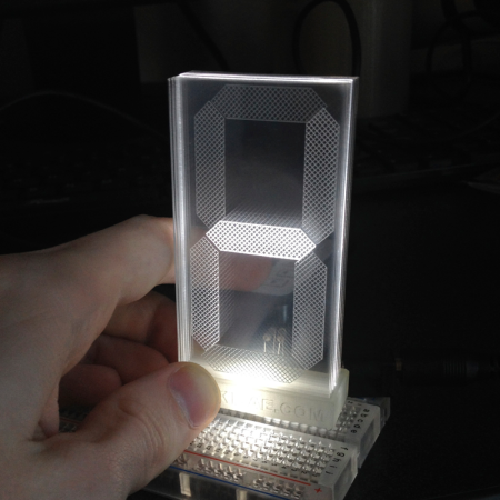
Though [Connor] labels it as a work in progress, we’re pretty impressed with how polished his transparent 7-segment display looks. It’s also deceptively simple.
The build uses a stack of seven different acrylic panes, one in front of the other, each with a different segment engraved onto its face. The assembly of panes sits on a small mount which is placed over seven rows of LEDs, with 5 LEDs per row. [Connor] left an air gap between each of the seven individual acrylic panes to clearly distinguish which was lit and to match the separation of the LED rows. To display a number, he simply illuminates the appropriate LED rows, which scatter light across the engraved part without spilling over into another pane.
You can find a brief overview and some schematics on [Connor's] website, and stick around for the video demonstration below. We’ve featured [Connor's] work before; if you missed his LCD data transfer hack you should check it out!
Use the Maxim MAX7219 LED display driver with Arduino in Chapter 56 of our Arduino Tutorials. The first chapter is here, the complete series is detailed here.
Introduction
Sooner or later Arduino enthusiasts and beginners alike will come across the MAX7219 IC. And for good reason, it’s a simple and somewhat inexpensive method of controlling 64 LEDs in either matrix or numeric display form. Furthermore they can be chained together to control two or more units for even more LEDs. Overall – they’re a lot of fun and can also be quite useful, so let’s get started.
Here’s an example of a MAX7219 and another IC which is a functional equivalent, the AS1107 from Austria Microsystems. You might not see the AS1107 around much, but it can be cheaper – so don’t be afraid to use that instead:
When shopping for MAX7219s you may notice the wild price fluctuations between various sellers. We’ve researched that and have a separate article for your consideration.
At first glance you may think that it takes a lot of real estate, but it saves some as well. As mentioned earlier, the MAX7219 can completely control 64 individual LEDs – including maintaining equal brightness, and allowing you to adjust the brightness of the LEDs either with hardware or software (or both). It can refresh the LEDs at around 800 Hz, so no more flickering, uneven LED displays.
You can even switch the display off for power saving mode, and still send it data while it is off. And another good thing – when powered up, it keeps the LEDs off, so no wacky displays for the first seconds of operation. For more technical information, here is the data sheet: MAX7219.pdf. Now to put it to work for us – we’ll demonstrate using one or more 8 x 8 LED matrix displays, as well as 8 digits of 7-segment LED numbers.
Before continuing, download and install the LedControl Arduino library as it is essential for using the MAX7219.
Controlling LED matrix displays with the MAX7219
First of all, let’s examine the hardware side of things. Here is the pinout diagram for the MAX7219:
The MAX7219 drives eight LEDs at a time, and by rapidly switching banks of eight your eyes don’t see the changes. Wiring up a matrix is very simple – if you have a common matrix with the following schematic:
connect the MAX7219 pins labelled DP, A~F to the row pins respectively, and the MAX7219 pins labelled DIG0~7 to the column pins respectively. A total example circuit with the above matrix is as follows:
The circuit is quite straight forward, except we have a resistor between 5V and MAX7219 pin 18. The MAX7219 is a constant-current LED driver, and the value of the resistor is used to set the current flow to the LEDs. Have a look at table eleven on page eleven of the data sheet:
You’ll need to know the voltage and forward current for your LED matrix or numeric display, then match the value on the table. E.g. if you have a 2V 20 mA LED, your resistor value will be 28kΩ (the values are in kΩ). Finally, the MAX7219 serial in, load and clock pins will go to Arduino digital pins which are specified in the sketch. We’ll get to that in the moment, but before that let’s return to the matrix modules.
In the last few months there has been a proliferation of inexpensive kits that contain a MAX7219 or equivalent, and an LED matrix. These are great for experimenting with and can save you a lot of work – some examples of which are shown below:
At the top is an example from ebay, and the pair on the bottom are the units from a recent kit review. We’ll use these for our demonstrations as well.
Now for the sketch. You need the following two lines at the beginning of the sketch:
The first pulls in the library, and the second line sets up an instance to control. The four parameters are as follows:
the digital pin connected to pin 1 of the MAX7219 (“data in”)
the digital pin connected to pin 13 of the MAX7219 (“CLK or clock”)
the digital pin connected to pin 12 of the MAX7219 (“LOAD”)
The number of MAX7219s connected.
If you have more than one MAX7219, connect the DOUT (“data out”) pin of the first MAX7219 to pin 1 of the second, and so on. However the CLK and LOAD pins are all connected in parallel and then back to the Arduino.
Next, two more vital functions that you’d normally put in void setup():
lc.shutdown(0,false);
lc.setIntensity(0,8);
The first line above turns the LEDs connected to the MAX7219 on. If you set TRUE, you can send data to the MAX7219 but the LEDs will stay off. The second line adjusts the brightness of the LEDs in sixteen stages. For both of those functions (and all others from the LedControl) the first parameter is the number of the MAX7219 connected. If you have one, the parameter is zero… for two MAX7219s, it’s 1 and so on.
Finally, to turn an individual LED in the matrix on or off, use:
lc.setLed(0,col,row,true);
which turns on an LED positioned at col, row connected to MAX7219 #1. Change TRUE to FALSE to turn it off. These functions are demonstrated in the following sketch:
#include "LedControl.h" //  need the library
LedControl lc=LedControl(12,11,10,1); //

// pin 12 is connected to the MAX7219 pin 1
// pin 11 is connected to the CLK pin 13
// pin 10 is connected to LOAD pin 12
// 1 as we are only using 1 MAX7219

void setup()
{
  // the zero refers to the MAX7219 number, it is zero for 1 chip
  lc.shutdown(0,false);// turn off power saving, enables display
  lc.setIntensity(0,8);// sets brightness (0~15 possible values)
  lc.clearDisplay(0);// clear screen
}
void loop()
{
  for (int row=0; row<8; row++)
  {
    for (int col=0; col<8; col++)
    {
      lc.setLed(0,col,row,true); // turns on LED at col, row
      delay(25);
    }
  }

  for (int row=0; row<8; row++)
  {
    for (int col=0; col<8; col++)
    {
      lc.setLed(0,col,row,false); // turns off LED at col, row
      delay(25);
    }
  }
}
And a quick video of the results:
How about controlling two MAX7219s? Or more? The hardware modifications are easy – connect the serial data out pin from your first MAX7219 to the data in pin on the second (and so on), and the LOAD and CLOCK pins from the first MAX7219 connect to the second (and so on). You will of course still need the 5V, GND, resistor, capacitors etc. for the second and subsequent MAX7219.
You will also need to make a few changes in your sketch. The first is to tell it how many MAX7219s you’re using in the following line:
LedControl lc=LedControl(12,11,10,X);
by replacing X with the quantity. Then whenever you’re using a MAX7219 function, replace the (previously used) zero with the number of the MAX7219 you wish to address. They are numbered from zero upwards, with the MAX7219 directly connected to the Arduino as unit zero, then one etc. To demonstrate this, we replicate the previous example but with two MAX7219s:
#include "LedControl.h" //  need the library
LedControl lc=LedControl(12,11,10,2); //

// pin 12 is connected to the MAX7219 pin 1
// pin 11 is connected to the CLK pin 13
// pin 10 is connected to LOAD pin 12
// 1 as we are only using 1 MAX7219

void setup()
{
  lc.shutdown(0,false);// turn off power saving, enables display
  lc.setIntensity(0,8);// sets brightness (0~15 possible values)
  lc.clearDisplay(0);// clear screen

  lc.shutdown(1,false);// turn off power saving, enables display
  lc.setIntensity(1,8);// sets brightness (0~15 possible values)
  lc.clearDisplay(1);// clear screen
}

void loop()
{
  for (int row=0; row<8; row++)
  {
    for (int col=0; col<8; col++)
    {
      lc.setLed(0,col,row,true); // turns on LED at col, row
      lc.setLed(1,col,row,false); // turns on LED at col, row
      delay(25);
    }
  }

  for (int row=0; row<8; row++)
  {
    for (int col=0; col<8; col++)
    {
      lc.setLed(0,col,row,false); // turns off LED at col, row
      lc.setLed(1,col,row,true); // turns on LED at col, row
      delay(25);
    }
  }
}
And again, a quick demonstration:
Another fun use of the MAX7219 and LED matrices is to display scrolling text. For the case of simplicity we’ll use the LedControl library and the two LED matrix modules from the previous examples.
First our example sketch – it is quite long however most of this is due to defining the characters for each letter of the alphabet and so on. We’ll explain it at the other end!
// based on an orginal sketch by Arduino forum member "danigom"
// http://forum.arduino.cc/index.php?action=profile;u=188950

#include <avr/pgmspace.h>
#include <LedControl.h>

const int numDevices = 2;      // number of MAX7219s used
const long scrollDelay = 75;   // adjust scrolling speed

unsigned long bufferLong [14] = {0};

LedControl lc=LedControl(12,11,10,numDevices);

prog_uchar scrollText[] PROGMEM ={
    "  THE QUICK BROWN FOX JUMPED OVER THE LAZY DOG 1234567890 the quick brown fox jumped over the lazy dog   \0"};

void setup(){
    for (int x=0; x<numDevices; x++){
        lc.shutdown(x,false);       //The MAX72XX is in power-saving mode on startup
        lc.setIntensity(x,8);       // Set the brightness to default value
        lc.clearDisplay(x);         // and clear the display
    }
}

void loop(){
    scrollMessage(scrollText);
    scrollFont();
}

///////////////////////////////////////////////////////////////////////////////////////////////////////////////////

prog_uchar font5x7 [] PROGMEM = {      //Numeric Font Matrix (Arranged as 7x font data + 1x kerning data)
    B00000000,	//Space (Char 0x20)
    B00000000,
    B00000000,
    B00000000,
    B00000000,
    B00000000,
    B00000000,
    6,

    B10000000,	//!
    B10000000,
    B10000000,
    B10000000,
    B00000000,
    B00000000,
    B10000000,
    2,

    B10100000,	//"
    B10100000,
    B10100000,
    B00000000,
    B00000000,
    B00000000,
    B00000000,
    4,

    B01010000,	//#
    B01010000,
    B11111000,
    B01010000,
    B11111000,
    B01010000,
    B01010000,
    6,

    B00100000,	//$
    B01111000,
    B10100000,
    B01110000,
    B00101000,
    B11110000,
    B00100000,
    6,

    B11000000,	//%
    B11001000,
    B00010000,
    B00100000,
    B01000000,
    B10011000,
    B00011000,
    6,

    B01100000,	//&
    B10010000,
    B10100000,
    B01000000,
    B10101000,
    B10010000,
    B01101000,
    6,

    B11000000,	//'
    B01000000,
    B10000000,
    B00000000,
    B00000000,
    B00000000,
    B00000000,
    3,

    B00100000,	//(
    B01000000,
    B10000000,
    B10000000,
    B10000000,
    B01000000,
    B00100000,
    4,

    B10000000,	//)
    B01000000,
    B00100000,
    B00100000,
    B00100000,
    B01000000,
    B10000000,
    4,

    B00000000,	//*
    B00100000,
    B10101000,
    B01110000,
    B10101000,
    B00100000,
    B00000000,
    6,

    B00000000,	//+
    B00100000,
    B00100000,
    B11111000,
    B00100000,
    B00100000,
    B00000000,
    6,

    B00000000,	//,
    B00000000,
    B00000000,
    B00000000,
    B11000000,
    B01000000,
    B10000000,
    3,

    B00000000,	//-
    B00000000,
    B11111000,
    B00000000,
    B00000000,
    B00000000,
    B00000000,
    6,

    B00000000,	//.
    B00000000,
    B00000000,
    B00000000,
    B00000000,
    B11000000,
    B11000000,
    3,

    B00000000,	///
    B00001000,
    B00010000,
    B00100000,
    B01000000,
    B10000000,
    B00000000,
    6,

    B01110000,	//0
    B10001000,
    B10011000,
    B10101000,
    B11001000,
    B10001000,
    B01110000,
    6,

    B01000000,	//1
    B11000000,
    B01000000,
    B01000000,
    B01000000,
    B01000000,
    B11100000,
    4,

    B01110000,	//2
    B10001000,
    B00001000,
    B00010000,
    B00100000,
    B01000000,
    B11111000,
    6,

    B11111000,	//3
    B00010000,
    B00100000,
    B00010000,
    B00001000,
    B10001000,
    B01110000,
    6,

    B00010000,	//4
    B00110000,
    B01010000,
    B10010000,
    B11111000,
    B00010000,
    B00010000,
    6,

    B11111000,	//5
    B10000000,
    B11110000,
    B00001000,
    B00001000,
    B10001000,
    B01110000,
    6,

    B00110000,	//6
    B01000000,
    B10000000,
    B11110000,
    B10001000,
    B10001000,
    B01110000,
    6,

    B11111000,	//7
    B10001000,
    B00001000,
    B00010000,
    B00100000,
    B00100000,
    B00100000,
    6,

    B01110000,	//8
    B10001000,
    B10001000,
    B01110000,
    B10001000,
    B10001000,
    B01110000,
    6,

    B01110000,	//9
    B10001000,
    B10001000,
    B01111000,
    B00001000,
    B00010000,
    B01100000,
    6,

    B00000000,	//:
    B11000000,
    B11000000,
    B00000000,
    B11000000,
    B11000000,
    B00000000,
    3,

    B00000000,	//;
    B11000000,
    B11000000,
    B00000000,
    B11000000,
    B01000000,
    B10000000,
    3,

    B00010000,	//<
    B00100000,
    B01000000,
    B10000000,
    B01000000,
    B00100000,
    B00010000,
    5,

    B00000000,	//=
    B00000000,
    B11111000,
    B00000000,
    B11111000,
    B00000000,
    B00000000,
    6,

    B10000000,	//>
    B01000000,
    B00100000,
    B00010000,
    B00100000,
    B01000000,
    B10000000,
    5,

    B01110000,	//?
    B10001000,
    B00001000,
    B00010000,
    B00100000,
    B00000000,
    B00100000,
    6,

    B01110000,	//@
    B10001000,
    B00001000,
    B01101000,
    B10101000,
    B10101000,
    B01110000,
    6,

    B01110000,	//A
    B10001000,
    B10001000,
    B10001000,
    B11111000,
    B10001000,
    B10001000,
    6,

    B11110000,	//B
    B10001000,
    B10001000,
    B11110000,
    B10001000,
    B10001000,
    B11110000,
    6,

    B01110000,	//C
    B10001000,
    B10000000,
    B10000000,
    B10000000,
    B10001000,
    B01110000,
    6,

    B11100000,	//D
    B10010000,
    B10001000,
    B10001000,
    B10001000,
    B10010000,
    B11100000,
    6,

    B11111000,	//E
    B10000000,
    B10000000,
    B11110000,
    B10000000,
    B10000000,
    B11111000,
    6,

    B11111000,	//F
    B10000000,
    B10000000,
    B11110000,
    B10000000,
    B10000000,
    B10000000,
    6,

    B01110000,	//G
    B10001000,
    B10000000,
    B10111000,
    B10001000,
    B10001000,
    B01111000,
    6,

    B10001000,	//H
    B10001000,
    B10001000,
    B11111000,
    B10001000,
    B10001000,
    B10001000,
    6,

    B11100000,	//I
    B01000000,
    B01000000,
    B01000000,
    B01000000,
    B01000000,
    B11100000,
    4,

    B00111000,	//J
    B00010000,
    B00010000,
    B00010000,
    B00010000,
    B10010000,
    B01100000,
    6,

    B10001000,	//K
    B10010000,
    B10100000,
    B11000000,
    B10100000,
    B10010000,
    B10001000,
    6,

    B10000000,	//L
    B10000000,
    B10000000,
    B10000000,
    B10000000,
    B10000000,
    B11111000,
    6,

    B10001000,	//M
    B11011000,
    B10101000,
    B10101000,
    B10001000,
    B10001000,
    B10001000,
    6,

    B10001000,	//N
    B10001000,
    B11001000,
    B10101000,
    B10011000,
    B10001000,
    B10001000,
    6,

    B01110000,	//O
    B10001000,
    B10001000,
    B10001000,
    B10001000,
    B10001000,
    B01110000,
    6,

    B11110000,	//P
    B10001000,
    B10001000,
    B11110000,
    B10000000,
    B10000000,
    B10000000,
    6,

    B01110000,	//Q
    B10001000,
    B10001000,
    B10001000,
    B10101000,
    B10010000,
    B01101000,
    6,

    B11110000,	//R
    B10001000,
    B10001000,
    B11110000,
    B10100000,
    B10010000,
    B10001000,
    6,

    B01111000,	//S
    B10000000,
    B10000000,
    B01110000,
    B00001000,
    B00001000,
    B11110000,
    6,

    B11111000,	//T
    B00100000,
    B00100000,
    B00100000,
    B00100000,
    B00100000,
    B00100000,
    6,

    B10001000,	//U
    B10001000,
    B10001000,
    B10001000,
    B10001000,
    B10001000,
    B01110000,
    6,

    B10001000,	//V
    B10001000,
    B10001000,
    B10001000,
    B10001000,
    B01010000,
    B00100000,
    6,

    B10001000,	//W
    B10001000,
    B10001000,
    B10101000,
    B10101000,
    B10101000,
    B01010000,
    6,

    B10001000,	//X
    B10001000,
    B01010000,
    B00100000,
    B01010000,
    B10001000,
    B10001000,
    6,

    B10001000,	//Y
    B10001000,
    B10001000,
    B01010000,
    B00100000,
    B00100000,
    B00100000,
    6,

    B11111000,	//Z
    B00001000,
    B00010000,
    B00100000,
    B01000000,
    B10000000,
    B11111000,
    6,

    B11100000,	//[
    B10000000,
    B10000000,
    B10000000,
    B10000000,
    B10000000,
    B11100000,
    4,

    B00000000,	//(Backward Slash)
    B10000000,
    B01000000,
    B00100000,
    B00010000,
    B00001000,
    B00000000,
    6,

    B11100000,	//]
    B00100000,
    B00100000,
    B00100000,
    B00100000,
    B00100000,
    B11100000,
    4,

    B00100000,	//^
    B01010000,
    B10001000,
    B00000000,
    B00000000,
    B00000000,
    B00000000,
    6,

    B00000000,	//_
    B00000000,
    B00000000,
    B00000000,
    B00000000,
    B00000000,
    B11111000,
    6,

    B10000000,	//`
    B01000000,
    B00100000,
    B00000000,
    B00000000,
    B00000000,
    B00000000,
    4,

    B00000000,	//a
    B00000000,
    B01110000,
    B00001000,
    B01111000,
    B10001000,
    B01111000,
    6,

    B10000000,	//b
    B10000000,
    B10110000,
    B11001000,
    B10001000,
    B10001000,
    B11110000,
    6,

    B00000000,	//c
    B00000000,
    B01110000,
    B10001000,
    B10000000,
    B10001000,
    B01110000,
    6,

    B00001000,	//d
    B00001000,
    B01101000,
    B10011000,
    B10001000,
    B10001000,
    B01111000,
    6,

    B00000000,	//e
    B00000000,
    B01110000,
    B10001000,
    B11111000,
    B10000000,
    B01110000,
    6,

    B00110000,	//f
    B01001000,
    B01000000,
    B11100000,
    B01000000,
    B01000000,
    B01000000,
    6,

    B00000000,	//g
    B01111000,
    B10001000,
    B10001000,
    B01111000,
    B00001000,
    B01110000,
    6,

    B10000000,	//h
    B10000000,
    B10110000,
    B11001000,
    B10001000,
    B10001000,
    B10001000,
    6,

    B01000000,	//i
    B00000000,
    B11000000,
    B01000000,
    B01000000,
    B01000000,
    B11100000,
    4,

    B00010000,	//j
    B00000000,
    B00110000,
    B00010000,
    B00010000,
    B10010000,
    B01100000,
    5,

    B10000000,	//k
    B10000000,
    B10010000,
    B10100000,
    B11000000,
    B10100000,
    B10010000,
    5,

    B11000000,	//l
    B01000000,
    B01000000,
    B01000000,
    B01000000,
    B01000000,
    B11100000,
    4,

    B00000000,	//m
    B00000000,
    B11010000,
    B10101000,
    B10101000,
    B10001000,
    B10001000,
    6,

    B00000000,	//n
    B00000000,
    B10110000,
    B11001000,
    B10001000,
    B10001000,
    B10001000,
    6,

    B00000000,	//o
    B00000000,
    B01110000,
    B10001000,
    B10001000,
    B10001000,
    B01110000,
    6,

    B00000000,	//p
    B00000000,
    B11110000,
    B10001000,
    B11110000,
    B10000000,
    B10000000,
    6,

    B00000000,	//q
    B00000000,
    B01101000,
    B10011000,
    B01111000,
    B00001000,
    B00001000,
    6,

    B00000000,	//r
    B00000000,
    B10110000,
    B11001000,
    B10000000,
    B10000000,
    B10000000,
    6,

    B00000000,	//s
    B00000000,
    B01110000,
    B10000000,
    B01110000,
    B00001000,
    B11110000,
    6,

    B01000000,	//t
    B01000000,
    B11100000,
    B01000000,
    B01000000,
    B01001000,
    B00110000,
    6,

    B00000000,	//u
    B00000000,
    B10001000,
    B10001000,
    B10001000,
    B10011000,
    B01101000,
    6,

    B00000000,	//v
    B00000000,
    B10001000,
    B10001000,
    B10001000,
    B01010000,
    B00100000,
    6,

    B00000000,	//w
    B00000000,
    B10001000,
    B10101000,
    B10101000,
    B10101000,
    B01010000,
    6,

    B00000000,	//x
    B00000000,
    B10001000,
    B01010000,
    B00100000,
    B01010000,
    B10001000,
    6,

    B00000000,	//y
    B00000000,
    B10001000,
    B10001000,
    B01111000,
    B00001000,
    B01110000,
    6,

    B00000000,	//z
    B00000000,
    B11111000,
    B00010000,
    B00100000,
    B01000000,
    B11111000,
    6,

    B00100000,	//{
    B01000000,
    B01000000,
    B10000000,
    B01000000,
    B01000000,
    B00100000,
    4,

    B10000000,	//|
    B10000000,
    B10000000,
    B10000000,
    B10000000,
    B10000000,
    B10000000,
    2,

    B10000000,	//}
    B01000000,
    B01000000,
    B00100000,
    B01000000,
    B01000000,
    B10000000,
    4,

    B00000000,	//~
    B00000000,
    B00000000,
    B01101000,
    B10010000,
    B00000000,
    B00000000,
    6,

    B01100000,	// (Char 0x7F)
    B10010000,
    B10010000,
    B01100000,
    B00000000,
    B00000000,
    B00000000,
    5
};

void scrollFont() {
    for (int counter=0x20;counter<0x80;counter++){
        loadBufferLong(counter);
        delay(500);
    }
}

// Scroll Message
void scrollMessage(prog_uchar * messageString) {
    int counter = 0;
    int myChar=0;
    do {
        // read back a char
        myChar =  pgm_read_byte_near(messageString + counter);
        if (myChar != 0){
            loadBufferLong(myChar);
        }
        counter++;
    }
    while (myChar != 0);
}
// Load character into scroll buffer
void loadBufferLong(int ascii){
    if (ascii >= 0x20 && ascii <=0x7f){
        for (int a=0;a<7;a++){                      // Loop 7 times for a 5x7 font
            unsigned long c = pgm_read_byte_near(font5x7 + ((ascii - 0x20) * 8) + a);     // Index into character table to get row data
            unsigned long x = bufferLong [a*2];     // Load current scroll buffer
            x = x | c;                              // OR the new character onto end of current
            bufferLong [a*2] = x;                   // Store in buffer
        }
        byte count = pgm_read_byte_near(font5x7 +((ascii - 0x20) * 8) + 7);     // Index into character table for kerning data
        for (byte x=0; x<count;x++){
            rotateBufferLong();
            printBufferLong();
            delay(scrollDelay);
        }
    }
}
// Rotate the buffer
void rotateBufferLong(){
    for (int a=0;a<7;a++){                      // Loop 7 times for a 5x7 font
        unsigned long x = bufferLong [a*2];     // Get low buffer entry
        byte b = bitRead(x,31);                 // Copy high order bit that gets lost in rotation
        x = x<<1;                               // Rotate left one bit
        bufferLong [a*2] = x;                   // Store new low buffer
        x = bufferLong [a*2+1];                 // Get high buffer entry
        x = x<<1;                               // Rotate left one bit
        bitWrite(x,0,b);                        // Store saved bit
        bufferLong [a*2+1] = x;                 // Store new high buffer
    }
}
// Display Buffer on LED matrix
void printBufferLong(){
  for (int a=0;a<7;a++){                    // Loop 7 times for a 5x7 font
    unsigned long x = bufferLong [a*2+1];   // Get high buffer entry
    byte y = x;                             // Mask off first character
    lc.setRow(3,a,y);                       // Send row to relevent MAX7219 chip
    x = bufferLong [a*2];                   // Get low buffer entry
    y = (x>>24);                            // Mask off second character
    lc.setRow(2,a,y);                       // Send row to relevent MAX7219 chip
    y = (x>>16);                            // Mask off third character
    lc.setRow(1,a,y);                       // Send row to relevent MAX7219 chip
    y = (x>>8);                             // Mask off forth character
    lc.setRow(0,a,y);                       // Send row to relevent MAX7219 chip
  }
}
The pertinent parts are at the top of the sketch – the following line sets the number of MAX7219s in the hardware:
const int numDevices = 2;
The following can be adjusted to change the speed of text scrolling:
const long scrollDelay = 75;
… then place the text to scroll in the following (for example):
prog_uchar scrollText[] PROGMEM ={
    "  THE QUICK BROWN FOX JUMPED OVER THE LAZY DOG 1234567890 the quick brown fox jumped over the lazy dog   \0"};
Finally – to scroll the text on demand, use the following:
scrollMessage(scrollText);
You can then incorporate the code into your own sketches. And a video of the example sketch in action:
Although we used the LedControl library, there are many others out there for scrolling text. One interesting example is Parola – which is incredibly customisable. If you’re looking for a much larger device to scroll text, check out the Freetronics DMD range.
Controlling LED numeric displays with the MAX7219
Using the MAX7219 and the LedControl library you can also drive numeric LED displays – up to eight digits from the one MAX7219. This gives you the ability to make various numeric displays that are clear to read and easy to control. When shopping around for numeric LED displays, make sure you have the common-cathode type.
Connecting numeric displays is quite simple, consider the following schematic which should appear familiar by now:
The schematic shows the connections for modules or groups of up to eight digits. Each digit’s A~F and dp (decimal point) anodes connect together to the MAX7219, and each digit’s cathode connects in order as well. The MAX7219 will display each digit in turn by using one cathode at a time. Of course if you want more than eight digits, connect another MAX7219 just as we did with the LED matrices previously.
The required code in the sketch is identical to the LED matrix code, however to display individual digits we use:
lc.setDigit(A, B, C, D);
where A is the MAX7219 we’re using, B is the digit to use (from a possible 0 to 7), C is the digit to display (0~9… if you use 10~15 it will display A~F respectively) and D is false/true (digit on or off). You can also send basic characters such as a dash “-” with the following:
lc.setChar(A, B,'-',false);
Now let’s put together an example of eight digits:
#include "LedControl.h" //  need the library
LedControl lc=LedControl(12,11,10,1); // lc is our object
// pin 12 is connected to the MAX7219 pin 1
// pin 11 is connected to the CLK pin 13
// pin 10 is connected to LOAD pin 12
// 1 as we are only using 1 MAX7219
void setup()
{
  // the zero refers to the MAX7219 number, it is zero for 1 chip
  lc.shutdown(0,false);// turn off power saving, enables display
  lc.setIntensity(0,8);// sets brightness (0~15 possible values)
  lc.clearDisplay(0);// clear screen
}
void loop()
{
  for (int a=0; a<8; a++)
  {
    lc.setDigit(0,a,a,true);
    delay(100);
  }
  for (int a=0; a<8; a++)
  {
    lc.setDigit(0,a,8,1);
    delay(100);
  }
  for (int a=0; a<8; a++)
  {
    lc.setDigit(0,a,0,false);
    delay(100);
  }
  for (int a=0; a<8; a++)
  {
    lc.setChar(0,a,' ',false);
    delay(100);
  }
  for (int a=0; a<8; a++)
  {
    lc.setChar(0,a,'-',false);
    delay(100);
  }
  for (int a=0; a<8; a++)
  {
    lc.setChar(0,a,' ',false);
    delay(100);
  }
}
and the sketch in action:
Conclusion
By now you’re on your way to controlling an incredibly useful part with your Arduino. Don’t forget – there are many variations of Arduino libraries for the MAX7219, we can’t cover each one – so have fun and experiment with them. And if you enjoyed the tutorial, or want to introduce someone else to the interesting world of Arduino – check out my book (now in a third printing!) “Arduino Workshop” from No Starch Press.
In the meanwhile have fun and keep checking into tronixstuff.com. Why not follow things on twitter, Google+, subscribe for email updates or RSS using the links on the right-hand column? And join our friendly Google Group – dedicated to the projects and related items on this website. Sign up – it’s free, helpful to each other – and we can all learn something.
The purpose of this article is to demonstrate the use of the second (here’s the first) interesting LED display module I discovered on the dealextreme website, for example:
As you can see the display unit holds a total of sixteen seven-segment LED digits using four modules. However thanks to the use of the TM1640 controller IC…
… the entire display is controlled with only four wires – 5V, GND, data in and clock:
Here is the data sheet for the TM1640. The board also ships with the 30cm long four-wire lead and fitted plug. Finally, there is a ‘power on’ LED on the right-hand end of the board:
Getting Started
Now to make things happen. From a hardware perspective – it couldn’t be easier. Connect the 5V and GND leads to … 5V and GND. The data and clock leads will connect to two Arduino digital pins. That’s it. The maximum current drawn by the display with all segments on is ~213mA:
So you should be able to drive this from a normal Arduino-compatible board without any hassle. Please note that the TM1640 IC does heat up somewhat, so you may want to consider some sort of heatsink if intending to max out the display in this manner.
From the software side of things you will need to download and install the TM1638 library (yes) which also handles the TM1640 chip. To simply display text from a string on the display, examine the following sketch:
Which will display:
The sixteen digit binary number in the module.setDisplayToString() line controls the decimal points – 0 for off and 1 for on. For example, changing it to
will display:
You can also display text in a somewhat readable form – using the characters available in this list. Displaying numbers is very easy, you can address each digit individually using:
where x is the digit, y is the position (0~15), and true/false is the decimal point. At this time you can’t just send a long integer down to the display, so you will need to either convert your numbers to a string or failing that, split it up into digits and display them one at a time.
In the following example sketch we display integers and unsigned integers by using the C command sprintf(). Note the use of %i to include an integer, and %u for unsigned integer:
And the resulting output:
Now you have an idea of what is possible, a variety of display options should spring to mind. For example:
Again, this display board was a random, successful find. When ordering from dealextreme, do so knowing that your order may take several weeks to arrive as they are not the fastest of online retailers; and your order may be coming from mainland China which can slow things down somewhat. Otherwise the module worked well and considering the minimal I/O and code requirements, is a very good deal.
Have fun and keep checking into tronixstuff.com. Why not follow things on twitter, Google+, subscribe for email updates or RSS using the links on the right-hand column, or join our Google Group – dedicated to the projects and related items on this website. Sign up – it’s free, helpful to each other – and we can all learn something.
Today we are going to examine the Maxim MAX7219 LED display driver IC. The reason for doing so is to show you how something that used to be quite complex can be made very simple – and that is what all this technology is for, isn’t it?
If you have ever tried to control lots of LEDs, or more than two or three 7-segment displays, or even an LED matrix, you realise that there is quite a lot of work to do on the software and hardware side of things. It usually involves lots of shift registers, switching transistors, and some nifty coding to get everything working. And then your code is too large, so the resulting display scans slow enough to see it flicker, etc.
Not any more! The MAX7219 combined with a great library (well for Arduino anyway) solves all the headaches in no time. After using it for the first time today I was briefly angry for not finding out about it sooner… better late than never.
First of all, let’s have a look:
Yes, at first glance you may think that it takes a lot of real estate, but it saves some as well. This chip can completely control 64 individual LEDs, including maintaining equal brightness, and allowing you to adjust the brightness of the LEDs either with hardware or software (or both). It can refresh the LEDs at around 800 Hz, so no more flickering, uneven LED displays. You can even switch the display off for power saving mode, and still send it data while it is off. And another good thing – when powered up, it keeps the LEDs off, so no wacky displays for the first seconds of operation.
Interfacing the MAX7219 is also very simple, you only need three digital output pins from a microncontroller, 5 volts and ground. Up to eight ICs can be cascaded to control up to 512 LEDs at once – from only three data pins. Wow. However, controlling all these LEDs will require a power supply that can allow 330 mA just for the IC, so you can’t just run this off your Ardiuino – you will need external power. Nothing an LM7805 regulator cannot fix.
For more technical information, here is the data sheet: MAX7219.pdf. Now to put it to work for us – this article will demonstrate using an 8 x 8 LED matrix, as well as 8 digits of 7-segment LED numbers. First of all, let’s examine the hardware side of things. Here is the pinout diagram for the IC:
At this point I should mention it is designed for common-cathode display systems.
One example would be an LED matrix, such as:
Normally you would have to program to switch on individual rows and columns, and repeat those commands in software, as well as using switching transistors or a 74HC4066 to control the cathodes.
Another example is a multi-digit 7-segment LED module – current flows in through the anode pins, and each digit is illuminated only when its cathode is connected to ground. Such as this unit:
It has input pins for each of the eight LED elements, and four cathode pins, one for each digit. We can use two of these displays with the MAX7219 very easily, as you will see below.
An example circuit to demonstrate using the matrix is below. Note the lack of resistors and transistors:
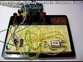
When using with (for example) an arduino-type board, you would connect serial data in, clock, and load to three digital pins. The resistor is the hardware control via limiting current to the LEDs. My examples use a 1k0 1/4-watt value. If you are going to experiment with this value, refer to page 10 of the data sheet first. Furthermore, ensure the ground of the MAX7219 is connected to the ground of the microcontroller. The capacitors are used to reduce supply current ripple. And here is the demonstration circuit on the breadboard:
In the above photo, the five wires on the left are connected to the Arduino board (5V, GND, load, clock, data). The two wires from the terminal block head to my DIY 5v power supply.
Now it is time to examine the software aspect, or how to control the MAX7219. My knowledge of microcontrollers is currently only Arduino, so we will use that for this review. Thankfully there is an excellent library that has been specifically written for the MAX7219 – the LedControllibrary. You will need to download and install the library from the LedControl page. If you need guidance on installing a library, please visit here.
The author has done a marvellous job of documenting his library, so I will briefly describe the basic functions you need to get things blinking. Here is a very basic demonstration sketch:
#include "LedControl.h" // need the library
LedControl lc=LedControl(12,11,10,1); // lc is our object
// pin 12 is connected to the MAX7219 pin 1
// pin 11 is connected to the CLK pin 13
// pin 10 is connected to LOAD pin 12
// 1 as we are only using 1 MAX7219
void setup()
{
// the zero refers to the MAX7219 number, it is zero for 1 chip
lc.shutdown(0,false);// turn off power saving, enables display
lc.setIntensity(0,8);// sets brightness (0~15 possible values)
lc.clearDisplay(0);// clear screen
}
void loop()
{
for (int row=0; row<8; row++)
{
for (int col=0; col<8; col++)
{
lc.setLed(0,col,row,true); // turns on LED at col, row
delay(10);
lc.setLed(0,col,row,false); // turns off LED at col, row
delay(10);
}
}
}
Using the lc.setLed() saves a lot of code, as the chip will hold the display on until it is told otherwise, you don’t need to program in a delay loop. You can just enter X and Y coordinates for the LED to switch on.
To switch off the display to save power, use lc.shutdown(0, true); – replace true with false to switch it back on again.
The video clip below is more of a detailed demonstration, using the schematic above, and this sketch:
Notice how altering the brightness up and down causes a nice “breathing” affect. However, don’t run that type of thing for too long, the MAX7219 does warm up nicely after about ten minutes of running all LEDs at once at full brightness…
Question – What was the manufacturing week and year for my MAX7219?
Now it is time to examine how the MAX7219 deals with seven-segment LED display modules. It can handle up to eight digits, so I have two four-digit display modules to use. The anodes will be connected, so they behave as one single eight -digit unit. Here is the schematic:
And here is the demonstration circuit on the breadboard:
Now to examine the functions to control these displays. Once again, be sure to have the LedControl library as used with the matrix. Here is another simple sketch:
#include "LedControl.h" //  need the library
LedControl lc=LedControl(12,11,10,1); // lc is our object
// pin 12 is connected to the MAX7219 pin 1
// pin 11 is connected to the CLK pin 13
// pin 10 is connected to LOAD pin 12
// 1 as we are only using 1 MAX7219
void setup()
{
  // the zero refers to the MAX7219 number, it is zero for 1 chip
  lc.shutdown(0,false);// turn off power saving, enables display
  lc.setIntensity(0,8);// sets brightness (0~15 possible values)
  lc.clearDisplay(0);// clear screen
}
void loop()
{
  for (int a=0; a<8; a++)
  {
    lc.setDigit(0,a,a,true);
    delay(100);
  }
  for (int a=0; a<8; a++)
  {
    lc.setDigit(0,a,8,1);
    delay(100);
  }
  for (int a=0; a<8; a++)
  {
    lc.setDigit(0,a,0,false);
    delay(100);
  }
  for (int a=0; a<8; a++)
  {
    lc.setChar(0,a,' ',false);
    delay(100);
  }
  for (int a=0; a<8; a++)
  {
    lc.setChar(0,a,'-',false);
    delay(100);
  }
  for (int a=0; a<8; a++)
  {
    lc.setChar(0,a,' ',false);
    delay(100);
  }
}
Once again, the use of the LedControl library certainly makes things easier. The difference between setChar() and setDigit is that the former can also write A~F, space, and a few other letters that are legible when used with a 7-segment display. Here is a video of the above sketch in action:
As you can see, driving all those LED digits is now a piece of cake. To think twenty years ago we used to muck about with various 4000-series ICs, decimal to BCD converters and so on. The MAX7219 just does it all. Now that I have learned how to make a nice huge display – there is only one thing to do… make another clock! It uses an arduino board, and my RTC shield. Here is the sketch: maxclock.pdf, and the clock in action:
Well that’s enough blinkiness for now, I could spend a week making displays with the MAX7219. In all honesty, I can say that it makes life exponentially easier when trying to control more than one LED with a microcontroller. Therefore it really is highly recommended. The only catch is the MAX7219 isn’t the cheapest IC out there. eBay seems to be full of counterfeit versions – just compare the Maxim Direct 1000+ price against the eBay price – so please avoid disappointment, support your local teams and buy from a reputable distributor. Living in Australia, mine came from Little Bird Electronics. So have fun!
If you have any questions at all please leave a comment (below). We also have a Google Group dedicated to the projects and related items on the website – please sign up, it’s free and we can all learn something. High resolution photosare available from flickr.
Otherwise, have fun, stay safe, be good to each other – and make something!
[Note – the MAX7219 was purchased by myself personally and reviewed without notifying the manufacturer or retailer]
Hello once again to our weekly Arduino instalment. This week are up to all sorts of things, including: more shiftiness with shift registers, more maths, 7-segment displays, arduinise a remote control car, and finally make our own electronic game! Wow – let’s get cracking…
In the last chapter we started using a 74HC595 shift register to control eight output pins with only three pins on the Arduino. That was all very interesting and useful – but there is more! You can link two or more shift registers together to control more pins! How? First of all, there is pin we haven’t looked at yet – pin 9 on the ’595. This is “data out”. If we connect this to the data in pin (14) on another ’595, the the first shift register can shift a byte of data to the next shift register, and so on.
Recall from our exercise 4.1, this part of the sketch:
digitalWrite(latchpin, LOW);
shiftOut(datapin, clockpin, MSBFIRST, loopy);
digitalWrite(latchpin, HIGH);
If we add another shiftOut(); command after the first one, we are sending two bytes of data to the registers. In this situation the first byte is accepted by the first shift register (the one with its data in pin [14] connected to the Arduino), and when the next byte is sent down the data line, it “pushes” the byte in the first shift register into the second shift register, leaving the second byte in the first shift register.
So now we are controlling SIXTEEN output pins with only three Arduino output pins. And yes – you can have a third, fourth … if anyone sends me a link to a Youtube clip showing this in action with 8 x 74HC595s, I will send them a prize. So, how do we do it? The code is easy, here is the sketch: Example 5.1
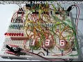
On the hardware side, it is also quite simple. If you love blinking LEDs this will make your day. It is the same as exercise 4.1, but you have another 74HC595 connected to another 8 LEDS. The clock and latch pins of both ’595s are linked together, and there is a link between pin 9 of the first register and pin 14 of the second. Below is a photo of my layout:
and a video:
Can you think of anything that has seven or eight LEDs? Hopefully this photo will refresh your memory:
Quickie – if you want to find out the remainder from a quotient, use modulo – “%”. For example:
a = 10 % 3;
returns a value of 1; as 10 divided by 3 is 3 remainder 1.
and
If you need to convert a floating-point number to an integer, it is easy. Use int();. It does not round up or down, only removes the fraction and leaves the integer.
Anyhow, now we can consider controlling these numeric displays with our arduino via the 74HC595. It is tempting to always use an LCD, but if you only need to display a few digits, or need a very high visibility, LED displays are the best option. Futhermore, they use a lot less current than a backlit LCD, and can be read from quite a distance away. A 7-segment display consists of eight LEDs arrange to form the digit eight, with a decimal point. Here is an example pinout digram:
Note that pinouts can vary, always get the data sheet if possible.
Displays can either be conmmon-anode, or common-cathode. That is, either all the LED segment anodes are common, or all the cathodes are common. Normally we will use common-cathode, as we are “sourcing” current from our shift register through a resistor (560 ohm), through the LED then to ground. If you use a common-anode, you need to “sink” current from +5v, through the resistor and LED, then into the controller IC. Now you can imagine how to display digits using this type of display – we just need to shiftout(); a byte to our shift register that is equavalent to the binary representation of the number you want to display.
Huh?
Let’s say we want to display the number ’8′ on the display. You will need to light up all the pins except for the decimal point. Unfortunately not all 7-segment displays are the same, so you need to work out which pinout is for each segment (see your data sheet) and then find the appropriate binary number to represent the pins needed, then convert that to a base-10 number to send to the display. I have created a table to make this easier:
Now let’s wire up one 7-segment display to our Arduino and see it work. Instead of the eight LEDs used in exercise 4.1 there is the display module. For reference the pinouts for my module were (7,6,4,2,1,9,10,5,3,8) = (a,b,c,d,e,f,g,DP, C, C) where DP is the decimal point and C is a cathode (which goes to GND). The sketch: example5p2.pdf. Note in the sketch that the decimal point is also used; it’s byte value in this example is 128. If you add 128 to the value of loopy[] in the sketch, the decimal point will be used with the numbers.
and the video:
There you go – easily done. Now it is time for you to do some work!
Exercise 5.1
Produce a circuit to count from 0 to 99 and back, using two displays and shift-registers. It isn’t that difficult, the hardware is basically the same as example 5.1 but using 7-segment displays.
You will need:
Your standard Arduino setup (computer, cable, Duemilanove)
You are probably wondering how on earth to separate the digits once the count hits 10… a hint: 34 modulo 10 = 4. 34 divided by 10 = 3.4 … but 3.4 isn’t an integer. While you are thinking, here is the shot of my layout:
I hope you have gained more of an understanding of the possibilities available with shift registers. We will contiunue with more next week.
However, next on our agenda is some real-world hacking. This section of the chapter is more of a commentary than the usual format, but I hope you find it interesting and you receive some inspiration or ideas after reading it.
Although we have been having fun (well I have been, hopefully someone else is as well) making things on our desks or work benches, it is time to slowly enter the real world and hack something up. The other day I was in a variety store to buy some glue, and happened across a very cheap remote-control car. After noticing it had full directional control (left/right, forwards/backwards) it occured to me that we could control it with an arduino. So $9 later here it is on my desk:
Naturally I stopped everything else and had a play with it. But by crikey it was very fast:
The first thing to do would be slow this baby down. Due to the …cheapness of the product it did not have variable speed control. So the first thing to do was pull the body off to see what we had to work with:
The design is very simple, with one motor controlling the steering, and one for the speed. Luckily for me there were four wires heading to the motor from the PCB, and the were very easy to get to.
Normally we could use pulse-width modulation to slow motors down, but I don’t think we could send a PWM signal over radio control. Instead, it would be easier to reduce the voltage going to the drive motor in order to slow it down. So with the car up on blocks, the motor was set to forward with the remote and I measure the voltages across the four wires. Black and green was +3.7 in forwards, nothing in reverse, black and red was the same in reverse, and nothing forwards. Easy – just find out how much current the motor draws at full speed and then we can use Ohm’s law (voltage = current x resistance) to calculate the value of a resistor to slow it down about 70% or so.
The motor initially drew ~500 mA to start up and then reduced to ~250 mA once it got going after around one second. However, a various range of resistors from 10 to 120 ohm didn’t really seem to have much effect, and a 560 ohm knocked it out all together. So instead of trying to control speed with a hardware method, we will try with a software method… perhaps try PWM after all, or create our own.
But now, time to get the arduino interfaced with the transmitter unit. Firstly I reassembled the car, then started on the transmitter:
After cutting my finger trying to get the transmitted open, it eventually gave in and cracked open. But the effort was worth it – the control buttons were very simple rubber pads over the PCB spots:
Excellent – each controller was basically a SPDT switch, and there is plenty of space on the PCB to solder in some wires to run to the Arduino and a breadboard. The push buttons could be replaced with BC548 transistors controlled by our Arduino – the same we we controlled a relay in Chapter Three.
Next was to solder some wires from the PCB that could run to my breadboard:
The green wire is a common return, and the yellow wires are forwards, reverse, left and right. Now to set up the breadboard. Four digital out pins, connected to the base of a BC548 transistor via a 1k resistor. The emitters are connected to GND, which is also connected to the GND of the transmitter.
Just as I had finished making up the breadboard, after turning around to close a window my arm brushed the transmitter and it made a ‘crack’ noise.
My soldering had come unstuck. Oh well, it was only reverse! Time to get moving anyhow. Once again, I put the car up on blocks and uploaded the following sketch:
/*
Example 5.3
Control a toy remote control car with arduino
Chapter Five @ http://www.tronixstuff.com/tutorials
*/
int forward = 12;
int left = 9;
int right = 7;
int del = 5000;
void setup()
{
pinMode(forward, OUTPUT);
pinMode(left, OUTPUT);
pinMode(right, OUTPUT);
}
void loop()
{
digitalWrite(right, HIGH);
delay(1000);
digitalWrite(right, LOW);
delay(1000);
digitalWrite(left, HIGH);
delay(1000);
digitalWrite(left, LOW);
delay(1000);
digitalWrite(forward, HIGH);
delay(del);
digitalWrite(forward, LOW);
delay(1000);
}
It cycles throgh the three (working!) function of the car. Let’s see what happens:
That’s a good start, things are moving when we want them to move. However the car’s motors seem to be pulsing. Perhaps the resistor-transistor bridge to the arduino had something to do with that. So I threw caution to the wind and connected the digital output pins directly to the transmitter. Wow! That fixed it. The motors are going at full speed now
Using our knowledge of Arduino sketches it will be east to make this car to drive around. Let’s try that now… here is our sketch:
/*
Example 5.4
Control a toy remote control car with arduino – figure eight
Chapter Five @ http://www.tronixstuff.com/tutorials
*/
int forward = 12;
int left = 9;
int right = 7;
int del = 5000;
void setup()
{
pinMode(forward, OUTPUT);
pinMode(left, OUTPUT);
pinMode(right, OUTPUT);
}
// to make creating the car’s journey easier, here are some functions
void goleft(int runtime)
{
digitalWrite(left, HIGH); // tell the steering to turn left
digitalWrite(forward, HIGH); // move the car forward
delay(runtime);
digitalWrite(forward, LOW);
digitalWrite(left, LOW); // tell the steering to straighen up
}
void goright(int runtime)
{
digitalWrite(right, HIGH); // tell the steering to turn right
digitalWrite(forward, HIGH); // move the car forward
delay(runtime);
digitalWrite(forward, LOW);
digitalWrite(right, LOW); // tell the steering to straighen up
}
void goforward(int runtime)
// run the drive motor for “runtime” milliseconds
{
digitalWrite(forward, HIGH); // start the drive motor forwards
delay(runtime);
digitalWrite(forward, LOW); // stop the drive motor
}
void loop()
{
goforward(1000);
goleft(1000);
goright(1000);
}
For some reason now forwards made the car go backwards. And only when I removed the GND wire from the Arduino to the breadboard. Interesting, but perhaps a problem for another day.
There we have it. Our first attempt at taking over something from the outside world and arduinising it. Now it is back to our normal readings with an exercise!
Exercise 5.2
Once again it is your turn to create something. We have discussed binary numbers, shift registers, analogue and digital inputs and outputs, creating our own functions, how to use various displays, and much more. So our task now is to build a binary quiz game. This is a device that will:
display a number between 0 and 255 in binary (using 8 LEDs)
you will turn a potentiometer (variable resistor) to select a number between 0 and 255, and this number is displayed using three 7-segment displays
You then press a button to lock in your answer. The game will tell you if you are correct or incorrect
Basically a “Binary quiz” machine of some sort!
I realise this could be a lot easier using an LCD, but that is not part of the exercise. Try and use some imagination with regards to the user interface and the difficulty of the game. At first it does sound difficult, but can be done if you think about it. At first you should make a plan, or algorithm, of how it should behave. Just write in concise instructions what you want it to do and when. Then try and break your plan down into tasks that you can offload into their own functions. Some functions may even be broken down into small functions – there is nothing wrong with that – it helps with planning and keeps everything neat and tidy. You may even find yourself writing a few test sketches, to see how a sensor works and how to integrate it into your main sketch. Then put it all together and see!
You will need: (to recreate my example below)
Your standard Arduino setup (computer, cable, Duemilanove)
and a video of the game in operation. Upon turning on the power, the game says hello. You press the button to start the game. It will show a number in binary using the LEDs, and you select the base-10 equivalent using the potentiometer as a dial. When you select your answer, press the button - the quiz will tell you if you are correct and show your score; or if you are incorrect, it will show you the right answer and then your score.
I have set it to only ask a few questions per game for the sake of the demonstration:
And yes – here is the sketch for my answer to the exercise: exercise 5.2.pdf
At this point we are taking a week off from the tutorials, however chapter six will be published around 21st May. But stick around – we will have two new kit reviews, some great part reviews, and a new project published in the next 7 days, so subscribe and follow us – see the top right of this web page!
If you have any questions at all please leave a comment (below). If you would like to showcase your work from this article, email a picture or a link to john at tronixstuff dot com.
You might even win a prize. Don’t forget to check out the range of gear at Little Bird Electronics!
Planet Arduino is, or at the moment is wishing to become, an aggregation of public weblogs from around the world written by people who develop, play, think on Arduino platform and his son. The opinions expressed in those weblogs and hence this aggregation are those of the original authors. Entries on this page are owned by their authors. We do not edit, endorse or vouch for the contents of individual posts. For more information about Arduino please visit www.arduino.cc
You are currently browsing the archives for the 7-segment category.