Posts | Comments

Planet Arduino

Archive for the ‘binary’ Category

keyboard-3A custom keyboard could be right at your fingertips, so why are you still using that basic keyboard that came with your computer?

Read more on MAKE

The post 8 Crazy Keyboards That Will Trick Out Your Typing appeared first on Make: DIY Projects and Ideas for Makers.

Jan
16

When life gives you lemons, you make lemonade. When life gives you freezing cold temperatures and a yard full of snow, you make binary clocks out of ice. At least that’s what [Dennis] does, anyway.

[Dennis’] clock is made from several cylindrical blocks of ice stacked on top of one another. There are six columns of ice blocks. The blocks were made by pouring water into empty margarine containers and freezing them. Once they were frozen, [Dennis] bore a 5/16″ hole into the bottom of each block to house an LED. Wires ran from the LEDs back into the drainage port of a cooler.

The cooler housed the main electronics. The LED controller board is of [Dennis’] own design. It contains six TLC59282 chips allowing for control of up to 96 LEDs. Each chip has its output lines running to two RJ45 connectors. [Dennis] couldn’t just use one because one of the eight wires in the connector was used as a common power line. The main CPU is an Arduino. It’s hooked up to a DS3234 Real Time Clock in order to keep accurate time. The oscillator monitors temperature in order to keep accurate time even in the dead of winter.


Filed under: Arduino Hacks, led hacks
Jan
09

Binary Clock Would Make Doc Brown Proud

433MHz, arduino, arduino hacks, ATmega328, binary, binary clock, clock, dcf77, time Comments Off on Binary Clock Would Make Doc Brown Proud 

[Brett] was looking for a way to improve on an old binary clock project from 1996. His original clock used green LEDs to denote between a one or a zero. If the LED was lit up, that indicated a one. The problem was that the LEDs were too dim to be able to read them accurately from afar. He’s been wanting to improve on his project using seven segment displays, but until recently it has been cost prohibitive.

[Brett] wanted his new project to use 24 seven segment displays. Three rows of eight displays. To build something like this from basic components would require the ability to switch many different LEDs for each of the seven segment displays. [Brett] instead decided to make things easier by using seven segment display modules available from Tindie. These modules each contain eight displays and are controllable via a single serial line.

The clock’s brain is an ATmega328 running Arduino. The controller keeps accurate time using a DCF77 receiver module and a DCF77 Arduino library. The clock comes with three display modes. [Brett] didn’t want and physical buttons on his beautiful new clock, so he opted to use remote control instead. The Arduino is connected to a 433MHz receiver, which came paired with a small remote. Now [Brett] can change display modes using a remote control.

A secondary monochrome LCD display is used to display debugging information. It displays the time and date in a more easily readable format, as well as time sync information, signal quality, and other useful information. The whole thing is housed in a sleek black case, giving it a professional look.


Filed under: Arduino Hacks

Introduction

The subject of our latest kit review is the “Epoch Clock” from Maniacal Labs, a new organisation started by three young lads with some interesting ideas. Regular readers will know we love a clock – so when the opportunity came to review this one, we couldn’t say no.

At this point you may be thinking “what is Epoch time anyway?”. Good question! It is the number of seconds elapsed since the first of January, 1970 (UTC) – and used by Unix-based computers as the start of their time universe. (For more on the theory of Epoch time, check out Wikipedia). For example - 1379226077 Epoch time is Sun, 15 Sep 2013 06:21:17 GMT. That’s a lot of seconds. If you’re curious, you can do more calculations with the EpochTime website.

Moving forward, this clock kit will show Epoch time in full 32-bit binary glory, using a DS1307 real-time clock IC (with backup battery) and is controlled with an ATmega328P-PU – so you can modify the code easily with the Arduino IDE or WinAVR (etc).

Assembly

The creators have spent a lot of time on not only the packaging and out-of-box-experience, but also the documentation and setup guide – so as long as you’re fine with simple through-hole soldering the kit will not present any challenges. The kit arrives in a sturdy box:

binary epoch clock kit box

… with well packaged components. Everything is included for the finished product, as well as IC sockets, the RTC backup battery and a USB cable so you can power the clock from a USB hub:

binary epoch clock kit box contents

binary epoch clock kit parts contents

The PCB is a good thickness, and has a clear silk-screen and solder mask:

binary epoch clock kit PCB

binary epoch clock kit PCB bottom

Construction is simple, just follow the step-by-step instructions. Starting with the USB socket for power:

binary epoch clock kit USB socket

binary epoch clock kit USB socket bottom

… then the resistors:

binary epoch clock kit resistors

… the LEDs:

binary epoch clock kit first LEDs

… all 32 of them. Note that the LEDs don’t sit flush with the PCB, so a little effort is required to keep them aligned:

binary epoch clock kit all LEDs

 Then the rest of the components just fit as expected. I’ve also added the included header pins for an FTDI programming cable and ICSP to keep my options open:

binary epoch clock kit almost finished

Then simply fit the battery, insert the ICs and you’re done:

binary epoch clock kit finished

Using the clock

The microcontroller is pre-programmed, so you can use the clock straight away. You will however need to set the time first. To make this incredibly easy, there is a special web page that displays the current time and Epoch time, which steps you through the process of setting the time using the buttons.

Or with some code available on the kit github page and a programming cable, you can automatically sync it to the clock. Once setup, the battery will keep the current time in the RTC nicely. The clock is powered by 5V, which is easily supplied with the included USB cable, or you can always hack in your own feed.

So what does Epoch time in 32-bit binary look like? Here’s a short video of the clock in action:

Reading the time requires converting the binary number displayed with the LEDs back to a decimal number – which is of course the Epoch count of seconds since 1/1/1970. Math teachers will love this thing.

But wait, there’s more!

If you get tired of the blinking, there’s a test function which is enabled by holding down both buttons for a second, which turns the Epoch Clock into a nifty Larson Scanner:

To create your own sketches or examine the design files in more detail, it’s all on the clock github page. From a hardware perspective you have an ATmega328P-PU development board with a DS1307 battery-backed real-time clock – with 32 LEDs. So you could also create your own kind of clock or other multi-LED blinking project without too much effort. Review the EpochClockSchematic (.pdf) to examine this in more detail.

Conclusion

I really enjoyed this kit – it was easy to assemble, I learned something new and frankly the blinking LEDs can be quite soothing. The clock would make a great for a conversation-starter in the office, or would make an ideal gift for any Sheldon Cooper-types you might be associated with. Or have competitions to see who can convert the display to normal time. After shots.

Nevertheless it’s a fun and imaginative piece of kit, fully Open Hardware-compliant – and if you’ve made it this far – get some and have fun. Full-sized images are on flickr. Interested in Arduino? Check out my new book “Arduino Workshop” from No Starch Press.

In the meanwhile have fun and keep checking into tronixstuff.com. Why not follow things on twitterGoogle+, subscribe  for email updates or RSS using the links on the right-hand column? And join our friendly Google Group – dedicated to the projects and related items on this website. Sign up – it’s free, helpful to each other –  and we can all learn something.

[Note - The kit reviewed was a promotional consideration from Maniacal Labs]

The post Kit Review – Maniacal Labs Epoch Clock appeared first on tronixstuff.

This is part of a series titled “Getting Started with Arduino!” – A tutorial on the Arduino microcontrollers, to be read with the book “Getting Started with Arduino” (Massimo Banzi).

The first chapter is here.

Welcome back fellow arduidans!

This week is going to focus around the concept of real time, and how we can work with time to our advantage. (Perhaps working with time to our disadvantage is an oxymoron…) Once we have the ability to use time in our sketches, a whole new world of ideas and projects become possible. From a simple alarm clock, to complex timing automation systems, it can all be done with our Arduino and some brainpower. There is no time to waste, so let’s go!

First of all, there are a few mathematical and variable-type concepts to grasp in order to be able to understand the sketch requirements. It is a bit dry, but I will try and minimise it.

The first of these is binary-coded decimal.

Can you recall from chapter four how binary numbers worked? If not, have a look then come back. Binary coded decimal (or BCD) numbers are similar, but different… each digit is stored in a nibble of data. Remember when working with the 74HC595 shift registers, we sent bytes of data – a nibble is half of a byte. For example:

Below is a short clip of BCD in action – counting from 0 to 9 using LEDs:

However, remember each digit is one nibble, so to express larger numbers, you need more bits. For example, 12 would be 0001 0010; 256 is 0010 0101 0110, etc. Note that two BCD digits make up a byte. For example, the number 56 in BCD is 0101 0110,  which is 2 x 4 bits = 1 byte.

Next, we will need to work with variables that are bytes. Like any other variable, they can be declared easily, for example:

byte seconds = B11111;

B11111 is 31 in base 10, (that is, 2^4+2^3+2^2+2^1+2^0     or    16+8+4+2+1)

However, you can equate an integer into a byte variable. Here is a small sketch demonstrating this: example7.1.pdf

And the result:

If you printed off the results of the sketch in example 7.1, it would make a good cheat sheet for the Binary Quiz program in Chapter Five.

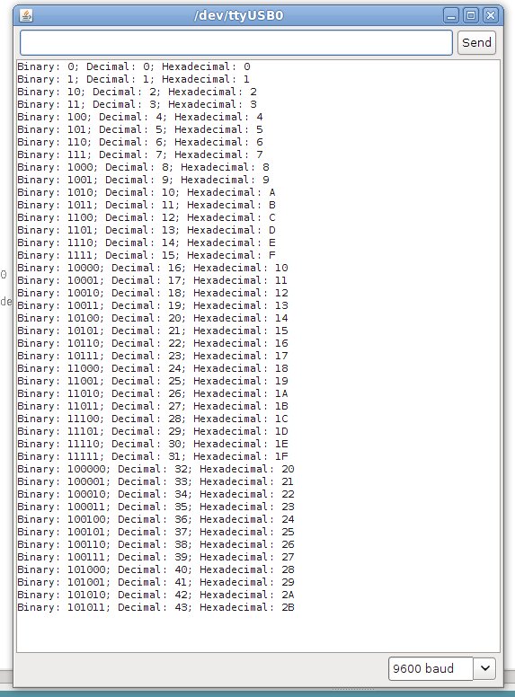
Anyhow, moving forward we now take a look at hexadecimal numbers. ‘Hex’ numbers are base-16, in that 16 digits/characters are used to represent numbers. Can you detect a pattern with the base-x numbers? Binary numbers are base-2, as they use 0 and 1; decimal numbers are base-10, as they use 0 to 9 – and hexadecimal numbers use 0 to 9 then A to F. Run the following sketch to see how they compare with binary and decimal: Example 7.2.pdf

Below is a screenshot of the result: the left column is hexadecimal, the centre binary, and the right decimal.

Unfortunately the IC we use for timing uses BCD, so we need to be able to convert to and from BCD to make sense of the timing data.

So now we have an understanding of BCD, binary, base-10 decimal, bytes, hexadecimal and nibbles. What a mouthful that was!

Coffee break.

Before we head back to timing, let’s look at a new function: switch… case. Say you needed to examine a variable, and make a decision based on the value of that variable, but there were more than two possible options. You could always use multiple if…then…else if functions, but that can be hard on the eyes. That is where switch… case comes in. It is quite self-explanatory, look at this example:

switch (zz) {
case 10:
//do something when variable zz equals 10
break;
case 20:
//do something when variable zz equals 20
break;
case 30:
// do something when variable equals 30
break;
default:
// if nothing else matches, do the default
// default is optional
}

OK, we’re back. It would seem that this chapter is all numbers and what not, but we are scaffolding our learning to be able to work with an integrated circuit that deals with the time for us. There is one last thing to look at then we can get on with timing things. And that thing is…

The I2C bus.

(There are two ways one could explain this, the simple way, and the detailed way. As this is “Getting Started with Arduino”, I will use the simple method. If you would like more detailed technical information, please read this document: NXP I2C Bus.pdf, or read the detailed website by NXP here)

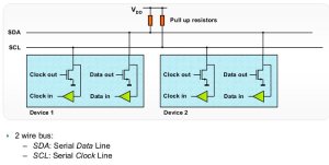
The I2C bus (also known as “two wire interface”) is the name of a type of interface between devices (integrated circuits) that allows them to communicate, control and share data with each other. (It was invented by Philips in the late 1970s. [Philips spun off their semiconductor division into NXP]).  This interchange of data occurs serially, using only  two wires (ergo two wire interface), one called SDA (serial data) and the other SCL (serial clock).

I2C bus – image from NXP documentation

A device can be a master, or a slave. In our situation, the Arduino is the master, and our time chip is the slave. Each chip on the bus has their own unique “address”, just like your home address, but in binary or in hexadecimal. You use the address in your sketch before communicating with the desired device on the I2C bus. There are many different types of devices that work with the I2C bus, from lighting controllers, analogue<> digital converters, LED drivers, the list is quite large. But the chip of interest to us, is the:

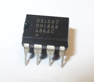
Maxim DS1307 Serial I2C real-time clock. Let’s have a look:

This amazing little chip, with only a few external components, can keep track of the time in 12-and 24-hour formats, day of week, calendar day, month and year, leap years, and the number of days in a month. Interestingly, it can also generate a square wave at 1Hz, 4kHz, 8kHz, or 32 kHz. For further technical information, here is the DS1307 data sheet.pdf. Note – the DS1307 does not work below 0 degrees Celsius/32 degrees Fahrenheit, if you need to go below freezing, use a DS1307N.

Using the DS1307 with our Arduino board is quite simple, either you can purchase a board with the chip and external circuitry ready to use, or make the circuit yourself. If you are going to do it yourself, here is the circuit diagram for you to follow: (click on image to enlarge)


The 3V battery is for backup purposes, a good example to use would be a CR2032 coin cell – however any 3V, long-life source should be fine. If you purchase a DS1307 board, check the battery voltage before using it…. my board kept forgetting the time, until I realised it shipped with a flat battery. The backup battery will not allow the chip to communicate when Vcc has dropped, it only allows the chip to keep time so it is accurate when the supply voltage is restored. Fair enough. The crystal is 32.768 kHz, and easily available. The capacitor is just a standard 0.1uF ceramic.

Now to the software, or working with the DS1307 in our sketches. To enable the I2C bus on Arduino there is the wire library which contains the functions required to communicate with devices connected to our I2C bus. The Arduino (Duemilanove) pins to use are analogue 4 (data) and analogue 5 (clock). If you are using a mega, they are 20 (data) and 21 (clock). There are only three things that we need to accomplish: initially setting the time data to the chip; reading the time data back from the chip; and enabling that 1Hz square-wave function (very useful – if you were making an LED clock, you could have a nice blinking LED).

First of all, we need to know the I2C address for our DS1307. It is 0×68 in hexadecimal. Addresses are unique to the device type, not each individual device of the same type.

Next, the DS1307 accepts or returns the timing data in a specific order…

  • seconds (always set seconds to zero, otherwise the oscillator in the DS1307 will stay off)
  • minutes
  • hours
  • day of week (You can set this number to any value between 1 and 7, e.g. 1 is Sunday, then 2 is Monday…)
  • day of month
  • month
  • year
  • control register (optional – used to control the square-wave function frequency and logic level)

… but it only accepts and returns this data in BCD. So – we’re going to need some functions to convert decimal numbers to BCD and vice-versa (unless you want to make a BCD clock …)

However, once again in the interests of trying to keep this simple, I will present you with a boilerplate sketch, with which you can copy and paste the code into your own creations. Please examine this file: example 7.3.pdf. Note that this sketch also activates the 1Hz square wave, available on pin 7. Below is a quick video of this square wave on my little oscilloscope:

This week we will look at only using 24-hour time; in the near future we will examine how to use 12-hour (AM/PM) time with the DS1307.

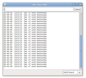
Here is a screen capture of the serial output box:

Now that you have the ability to send this time data to the serial output box, you can send it to other devices. For example, let’s make a simple LCD clock. It is very easy to modify our example 7.3 sketch, the only thing to take into account is the available space on the LCD module. To save time I am using the Electronic Brick kit to assemble this example. Below is a short clip of our LCD clock operating:

and here is the sketch: example 7.4.pdf. After seeing that clock fire up and work correctly, I felt really great – I hope you did too. Now let’s head back in time, to when digital clocks were all the rage…

Exercise 7.1

Using our Arduino, DS1307 clock chip, and the exact hardware from exercise 6.2 (except for the variable resistor, no need for that) – make a nice simple digital clock. It will only need to show the hours and minutes, unless you wish to add more display hardware. Have fun!

Here is my result, in video form:

and the sketch: exercise 7.1.pdf. Just an interesting note – after you upload your sketch to set the time; comment out the line to set the time, then upload the sketch a second time. Otherwise every time your clock loses power and reboots, it will start from the time defined in the sketch!

Another week over! And once again, I’m already excited about writing the next instalment… Congratulations to all those who took part and built something useful! Please subscribe (see the top right of this page) to receive notifications of new articles. High resolution photos are available from flickr.

If you have any questions at all please leave a comment (below). We also have a Google Group dedicated to the projects and related items on the website – please sign up, it’s free and we can all learn something -

If you would like to showcase your work from this article, email a picture or a link to john at tronixstuff dot com.

You might even win a prize. Don’t forget to check out the range of gear at Little Bird Electronics!

So have fun, stay safe and see you soon for our next instalment!


This is part of a series titled “Getting Started with Arduino!” – A tutorial on the Arduino microcontrollers, to be read with the book “Getting Started with Arduino” (Massimo Banzi).

The first chapter is here.

Welcome back fellow arduidans!

Hello once again to our weekly Arduino instalment. This week are up to all sorts of things, including: more shiftiness with shift registers, more maths, 7-segment displays, arduinise a remote control car, and finally make our own electronic game! Wow – let’s get cracking…

In the last chapter we started using a 74HC595 shift register to control eight output pins with only three pins on the Arduino. That was all very interesting and useful – but there is more! You can link two or more shift registers together to control more pins! How? First of all, there is pin we haven’t looked at yet – pin 9 on the ’595. This is “data out”. If we connect this to the data in pin (14) on another ’595, the the first shift register can shift a byte of data to the next shift register, and so on.

Recall from our exercise 4.1, this part of the sketch:

digitalWrite(latchpin, LOW);

shiftOut(datapin, clockpin, MSBFIRST, loopy);

digitalWrite(latchpin, HIGH);

If we add another shiftOut(); command after the first one, we are sending two bytes of data to the registers. In this situation the first byte is accepted by the first shift register (the one with its data in pin [14] connected to the Arduino), and when the next byte is sent down the data line, it “pushes” the byte in the first shift register into the second shift register, leaving the second byte in the first shift register.

So now we are controlling SIXTEEN output pins with only three Arduino output pins. And yes – you can have a third, fourth … if anyone sends me a link to a Youtube clip showing this in action with 8 x 74HC595s, I will send them a prize. So, how do we do it? The code is easy, here is the sketch: Example 5.1

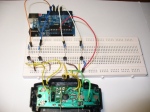
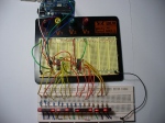
On the hardware side, it is also quite simple. If you love blinking LEDs this will make your day. It is the same as exercise 4.1, but you have another 74HC595 connected to another 8 LEDS. The clock and latch pins of both ’595s are linked together, and there is a link between pin 9 of the first register and pin 14 of the second. Below is a photo of my layout:
and a video:

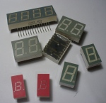
Can you think of anything that has seven or eight LEDs? Hopefully this photo will refresh your memory:
Quickie – if you want to find out the remainder from a quotient, use modulo – “%”. For example:

a = 10 % 3;

returns a value of 1; as 10 divided by 3 is 3 remainder 1.

and

If you need to convert a floating-point number to an integer, it is easy. Use int();. It does not round up or down, only removes the fraction and leaves the integer.

Anyhow, now we can consider controlling these numeric displays with our arduino via the 74HC595. It is tempting to always use an LCD, but if you only need to display a few digits, or need a very high visibility, LED displays are the best option. Futhermore, they use a lot less current than a backlit LCD, and can be read from quite a distance away. A 7-segment display consists of eight LEDs arrange to form the digit eight, with a decimal point. Here is an example pinout digram:

Note that pinouts can vary, always get the data sheet if possible.

Displays can either be conmmon-anode, or common-cathode. That is, either all the LED segment anodes are common, or all the cathodes are common. Normally we will use common-cathode, as we are “sourcing” current from our shift register through a resistor (560 ohm), through the LED then to ground. If you use a common-anode, you need to “sink” current from +5v, through the resistor and LED, then into the controller IC. Now you can imagine how to display digits using this type of display – we just need to shiftout(); a byte to our shift register that is equavalent to the binary representation of the number you want to display.

Huh?

Let’s say we want to display the number ’8′ on the display. You will need to light up all the pins except for the decimal point. Unfortunately not all 7-segment displays are the same, so you need to work out which pinout is for each segment (see your data sheet) and then find the appropriate binary number to represent the pins needed, then convert that to a base-10 number to send to the display. I have created a table to make this easier:

And here is a blank one for you to print out and use: blank pin table.pdf.

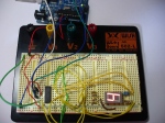
Now let’s wire up one 7-segment display to our Arduino and see it work. Instead of the eight LEDs used in exercise 4.1 there is the display module. For reference the pinouts for my module were (7,6,4,2,1,9,10,5,3,8) = (a,b,c,d,e,f,g,DP, C, C) where DP is the decimal point and C is a cathode (which goes to GND). The sketch: example5p2.pdf. Note in the sketch that the decimal point is also used; it’s byte value in this example is 128. If you add 128 to the value of loopy[] in the sketch, the decimal point will be used with the numbers.
and the video:

There you go – easily done. Now it is time for you to do some work!

Exercise 5.1

Produce a circuit to count from 0 to 99 and back, using two displays and shift-registers. It isn’t that difficult, the hardware is basically the same as example 5.1 but using 7-segment displays.

You will need:

  • Your standard Arduino setup (computer, cable, Duemilanove)
  • Two 7-segment, common-cathode displays
  • Two 74HC595 shift registers
  • 16 x 560 ohm 0.25 W resistors. For use as current limiters between the LED display segments and ground
  • a breadboard and some connecting wire
  • some water

You are probably wondering how on earth to separate the digits once the count hits 10… a hint: 34 modulo 10 = 4. 34 divided by 10 = 3.4 … but 3.4 isn’t an integer. While you are thinking, here is the shot of my layout:
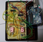
and the ubiquitous video:

And here is my sketch: exercise5.1.pdf

I hope you have gained more of an understanding of the possibilities available with shift registers. We will contiunue with more next week.
However, next on our agenda is some real-world hacking. This section of the chapter is more of a commentary than the usual format, but I hope you find it interesting and you receive some inspiration or ideas after reading it.

Although we have been having fun (well I have been, hopefully someone else is as well) making things on our desks or work benches, it is time to slowly enter the real world and hack something up. The other day I was in a variety store to buy some glue, and happened across a very cheap remote-control car. After noticing it had full directional control (left/right, forwards/backwards) it occured to me that we could control it with an arduino. So $9 later here it is on my desk:

Naturally I stopped everything else and had a play with it. But by crikey it was very fast:

The first thing to do would be slow this baby down. Due to the …cheapness of the product it did not have variable speed control. So the first thing to do was pull the body off to see what we had to work with:
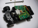
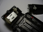
The design is very simple, with one motor controlling the steering, and one for the speed. Luckily for me there were four wires heading to the motor from the PCB, and the were very easy to get to.
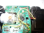
Normally we could use pulse-width modulation to slow motors down, but I don’t think we could send a PWM signal over radio control. Instead, it would be easier to reduce the voltage going to the drive motor in order to slow it down. So with the car up on blocks, the motor was set to forward with the remote and I measure the voltages across the four wires. Black and green was +3.7 in forwards, nothing in reverse, black and red was the same in reverse, and nothing forwards. Easy – just find out how much current the motor draws at full speed and then we can use Ohm’s law (voltage = current x resistance) to calculate the value of a resistor to slow it down about 70% or so.

The motor initially drew ~500 mA to start up and then reduced to ~250 mA once it got going after around one second. However, a various range of resistors from 10 to 120 ohm didn’t really seem to have much effect, and a 560 ohm knocked it out all together. So instead of trying to control speed with a hardware method, we will try with a software method… perhaps try PWM after all, or create our own.

But now, time to get the arduino interfaced with the transmitter unit. Firstly I reassembled the car, then started on the transmitter:
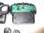
After cutting my finger trying to get the transmitted open, it eventually gave in and cracked open. But the effort was worth it – the control buttons were very simple rubber pads over the PCB spots:
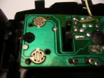
Excellent – each controller was basically a SPDT switch, and there is plenty of space on the PCB to solder in some wires to run to the Arduino and a breadboard. The push buttons could be replaced with BC548 transistors controlled by our Arduino – the same we we controlled a relay in Chapter Three.

Next was to solder some wires from the PCB that could run to my breadboard:
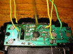
The green wire is a common return, and the yellow wires are forwards, reverse, left and right. Now to set up the breadboard. Four digital out pins, connected to the base of a BC548 transistor via a 1k resistor. The emitters are connected to GND, which is also connected to the GND of the transmitter.

Just as I had finished making up the breadboard, after turning around to close a window my arm brushed the transmitter and it made a ‘crack’ noise.
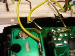
My soldering had come unstuck. Oh well, it was only reverse! Time to get moving anyhow. Once again, I put the car up on blocks and uploaded the following sketch:

/*

Example 5.3

Control a toy remote control car with arduino
Chapter Five @ http://www.tronixstuff.com/tutorials
*/
int forward = 12;
int left = 9;
int right = 7;
int del = 5000;
void setup()
{
pinMode(forward, OUTPUT);
pinMode(left, OUTPUT);
pinMode(right, OUTPUT);
}
void loop()
{
digitalWrite(right, HIGH);
delay(1000);
digitalWrite(right, LOW);
delay(1000);
digitalWrite(left, HIGH);
delay(1000);
digitalWrite(left, LOW);
delay(1000);
digitalWrite(forward, HIGH);
delay(del);
digitalWrite(forward, LOW);
delay(1000);

}

It cycles throgh the three (working!) function of the car. Let’s see what happens:

That’s a good start, things are moving when we want them to move. However the car’s motors seem to be pulsing. Perhaps the resistor-transistor bridge to the arduino had something to do with that. So I threw caution to the wind and connected the digital output pins directly to the transmitter. Wow! That fixed it. The motors are going at full speed now

Using our knowledge of Arduino sketches it will be east to make this car to drive around. Let’s try that now… here is our sketch:

/*

Example 5.4

Control a toy remote control car with arduino – figure eight

Chapter Five @ http://www.tronixstuff.com/tutorials

*/

int forward = 12;

int left = 9;

int right = 7;

int del = 5000;

void setup()

{

pinMode(forward, OUTPUT);

pinMode(left, OUTPUT);

pinMode(right, OUTPUT);

}

// to make creating the car’s journey easier, here are some functions

void goleft(int runtime)

{

digitalWrite(left, HIGH);  // tell the steering to turn left

digitalWrite(forward, HIGH); // move the car forward

delay(runtime);

digitalWrite(forward, LOW);

digitalWrite(left, LOW);  // tell the steering to straighen up

}

void goright(int runtime)

{

digitalWrite(right, HIGH);  // tell the steering to turn right

digitalWrite(forward, HIGH); // move the car forward

delay(runtime);

digitalWrite(forward, LOW);

digitalWrite(right, LOW);  // tell the steering to straighen up

}

void goforward(int runtime)

// run the drive motor for “runtime” milliseconds

{

digitalWrite(forward, HIGH);  // start the drive motor forwards

delay(runtime);

digitalWrite(forward, LOW); // stop the drive motor

}

void loop()

{

goforward(1000);

goleft(1000);

goright(1000);

}

For some reason now forwards made the car go backwards. And only when I removed the GND wire from the Arduino to the breadboard. Interesting, but perhaps a problem for another day.

There we have it. Our first attempt at taking over something from the outside world and arduinising it. Now it is back to our normal readings with an exercise!

Exercise 5.2

Once again it is your turn to create something. We have discussed binary numbers, shift registers, analogue and digital inputs and outputs, creating our own functions, how to use various displays, and much more. So our task now is to build a binary quiz game. This is a device that will:

  • display a number between 0 and 255 in binary (using 8 LEDs)
  • you will turn a potentiometer (variable resistor) to select a number between 0 and 255, and this number is displayed using three 7-segment displays
  • You then press a button to lock in your answer. The game will tell you if you are correct or incorrect
  • Basically a “Binary quiz” machine of some sort!

I realise this could be a lot easier using an LCD, but that is not part of the exercise. Try and use some imagination with regards to the user interface and the difficulty of the game. At first it does sound difficult, but can be done if you think about it. At first you should make a plan, or algorithm, of how it should behave. Just write in concise instructions what you want it to do and when. Then try and break your plan down into tasks that you can offload into their own functions. Some functions may even be broken down into small functions – there is nothing wrong with that – it helps with planning and keeps everything neat and tidy. You may even find yourself writing a few test sketches, to see how a sensor works and how to integrate it into your main sketch. Then put it all together and see!

You will need: (to recreate my example below)

  • Your standard Arduino setup (computer, cable, Duemilanove)
  • Three 7-segment, common-cathode displays
  • eight LEDs (for binary number display)
  • Four 74HC595 shift registers
  • 32 x 560 ohm 0.25 W resistors. For use as current limiters between the LED display segments and ground
  • a breadboard and some connecting wire
  • 10k linear potentiometer (variable resistor)
  • some water

For inspiration here is a photo of my layout:
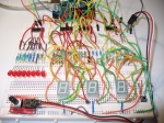

and a video of the game in operation. Upon turning on the power, the game says hello. You press the button to start the game. It will show a number in binary using the LEDs, and you select the base-10 equivalent using the potentiometer as a dial. When you select your answer, press the button  - the quiz will tell you if you are correct and show your score; or if you are incorrect, it will show you the right answer and then your score.

I have set it to only ask a few questions per game for the sake of the demonstration:

And yes – here is the sketch for my answer to the exercise: exercise 5.2.pdf

At this point we are taking a week off from the tutorials, however chapter six will be published around 21st May. But stick around – we will have two new kit reviews, some great part reviews, and a new project published in the next 7 days, so subscribe and follow us – see the top right of this web page!

High resolution images available at flickr.

If you have any questions at all please leave a comment (below). If you would like to showcase your work from this article, email a picture or a link to john at tronixstuff dot com.

You might even win a prize. Don’t forget to check out the range of gear at Little Bird Electronics!

So have fun, stay safe and see you  for our next instalment!


This is part of a series titled “Getting Started with Arduino!” – A tutorial on the Arduino microcontrollers, to be read with the book “Getting Started with Arduino” (Massimo Banzi).

The first chapter is here.

Welcome back fellow arduidans!

Hello once again to our weekly Arduino instalment. This instalment is a little early this week. This time we will be looking at getting more outputs from less pins, listening to some tunes, saying hooray to arrays, and even build a self-contained data logger!

So let’s go!

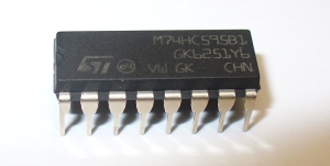
More pins from less – sounds too good to be true, doesn’t it? No, it is true and we can learn how to do this in conjunction with a special little IC, the 74HC595 Serial In/Parallel Out 8-bit Shift Register. Let’s say hello:

Before we get too carried away, we need to understand a little about bits, bytes and binary numbers.

A binary number can only uses zeros and ones to represent a value. Thus binary is also known as “base-2″, as it can only use two digits. Our most commonly used number types are base-10 (as it uses zero through to nine; hexadecimal is base-16 as it uses 0 to 9 and A to F). How can a binary number with only the use of two digits represent a larger number? It uses a lot of ones and zeros. Let’s examine a binary number, say 10101010. As this is a base-2 number, each digit represents 2 to the power of x, from x=0 onwards.

See how each digit of the binary number can represent a base-10 number. So the binary number above represents 85 in base-10 – the value 85 is the sum of the base-10 values.

Another example – 11111111 in binary equals 255 in base 10.

Now each digit in that binary number uses one ‘bit’ of memory, and eight bits make a byte. A byte is a special amount of data, as it matches perfectly with the number of output pins that the 74HC595 chip controls. (See, this wasn’t going to be a maths lesson after all). If we use our Arduino to send a number in base-10 out through a digital pin to the ’595, it will convert it to binary and set the matching output pins high or low.

So if you send the number 255 to the ’595, all of the output pins will go high. If you send it 01100110, only pins 1,2,5, and 6 will go high. Now can you imagine how this gives you extra digital output pins? The numbers between 0 and 255 can represent every possible combination of outputs on the ’595. Furthermore, each byte has a “most significant bit” and “least significant bit” – these are the left-most and right-most bits respectively.

Now to the doing part of things. Let’s look at the pinout of the 74HC595: (from Philips/NXP 74HC595 datasheet)

Pins Q0~Q7 are the output pins that we want to control. The Q7′ pin is unused, for now. ’595 pin 14 is the data pin, 12 is the latch pin and 11 is the clock pin. The data pin connects to a digital output pin on the Arduino. The latch pin is like a switch, when it is low the ’595 will accept data, when it is high, the ’595 goes deaf. The clock pin is toggled once the data has been received. So the procedure to get the data into a ’595 is this:

1) set the latch pin low (pin 12)

2) send the byte of data to the ’595 (pin 14)

3) toggle the clock pin (pin 11)

4) set the latch pin high (pin 12)

Pin 10 (reset) is connected to the +5V.

Thankfully there is a command that has parts 2 and 3 in one; you can use digitalWrite(); to take care of the latch duties. The command shiftOut(); is the key. The syntax is:

shiftout(a,b,c,d);

where:

a = the digital output pin that connects to the ’595 data pin (14);

b = the digital output pin that connects to the ’595 clock pin (11);

c can be either LSBFIRST or MSBFIRST. MSBFIRST means the ’595 will interpret the binary number from left to right; LSBFIRST will make it go right to left;

d = the actual number (0~255) that you want represented by the ’595 in binary output pins.

So if you wanted to switch on pins 1,2,5 and 6, with the rest low, you would execute the following:

digitalWrite(latchpin, LOW);

shiftOut(datapin, clockpin, MSBFIRST,102);

digitalWrite(latchpin, HIGH);

Now, what can you do with those ’595 output pins? More than you could imagine! Just remember the most current you can sink or source through each output pin is 35 milliamps.

For example:

  • an LED and a current-limiting resisor to earth… you could control many LEDs than normally possible with your Arduino;
  • an NPN transistor and something that draws more current like a motor or a larger lamp
  • an NPN transistor controlling a relay (remember?)

With two or more ’595s you can control a matrix of LEDs, 7-segment displays, and more – but that will be in the coming weeks.

For now, you have a good exercise to build familiarity with the shift-register process.

Exercise 4.1

Construct a simple circuit, that counts from 0~255 and displays the number in binary using LEDs. You will require the following:

  • Your standard Arduino setup (computer, cable, Duemilanove)
  • 8 LEDs of your choosing
  • One 74HC595 shift register
  • 8 x 560 ohm 0.25 W resistors. For use as current limiters between the LEDs and ground.
  • a breadboard and some connecting wire

The hardware is quite easy. Just remember that the anodes of the LEDs connect with the ’595, and the cathodes connect to the resistors which connect to ground. You can use the Arduino 5V and GND.

Here is what my layout looked like:

and of course a video – I have increased the speed of mine for the sake of the demonstration.

How did you go? Here is the sketch if you need some ideas – Ex 4.1

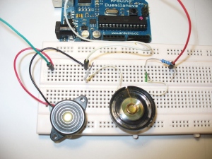
Next on the agenda today is another form of output – audio. Of course you already knew that, but until now we have not looked at (or should I say, listened to) the audio features of the Arduino system. The easiest way to get some noise is to use a piezo buzzer. An example of this is on the left hand side of the image below:

These are very simple to use and can be very loud and annoying. To get buzzing, just connect their positive lead to a digital output pin, and their negative lead to ground. Then you only have to change the digital pin to HIGH when you need a buzz. For example:

/* Example 4.1

Annoying buzzer!

CC by-sa v3.0

http://tronixstuff.wordpress.com */

void setup()

{

pinMode(12, OUTPUT);

}

void loop()

{

digitalWrite(12, HIGH);

delay(500);

digitalWrite(12, LOW);

delay(2000);

}

You won’t be subjected to a recording of it, as thankfully (!) my camera does not record audio…

However, you will want more than a buzz. Arduino has a tone(); command, which can generate a tone with a particular frequency for a duration. The syntax is:

tone(pin, frequency, duration);

where pin is the digital output pin the speaker is connected to, frequency in Hertz, duration in milliseconds. Easy!

If you omit the duration variable, the tone will be continuous, and can be stopped with notone();. Furthermore, the use of tone(); will interfere with PWM on pins 3 and 11, unless you are using an Arduino Mega.

Now, good choice for a speaker is one of those small 0.25w 8 ohm ones. My example is on the right in the photo above, taken from a musical plush toy. It has a 100 ohm resistor between the digital output pin and the speaker. Anyhow, let’s make some more annoying noise – hmm – a siren!

/* Example 4.2

Annoying siren

CC by-sa v3.0

http://tronixstuff.wordpress.com */

void setup()

{

pinMode(8, OUTPUT); // speker on pin 8

}

int del = 250; // for tone length

int lowrange = 2000; // the lowest frequency value to use

int highrange = 4000; //  the highest…

void loop()

{

// increasing tone

for (int a = lowrange; a<=highrange; a++)

{

tone (8, a, del);

}

// decreasing tone

for (int a = highrange; a>=lowrange; a–)

{

tone (8, a, del);

}

}

Phew! You can only take so much of that.

Array! Hooray? No… Arrays.

What is an array?

Let’s use an analogy from my old comp sci textbook. Firstly, you know what a variable is (you should by now). Think of this as an index card, with a piece of data written on it. For example, the number 8. Let’s get a few more index cards, and write one number on each one. 6, 7, 5, 3, 0, 9. So now you have seven pieces of data, or seven variables. They relate to each other in some way or another, and they could change, so we need a way to keep them together as a group for easier reference. So we put those cards in a small filing box, and we give that box a name, e.g. “Jenny”.

An array is that small filing box. It holds a series of variables of any type possible with arduino. To create an array, you need to define it like any other variable. For example, an array of 10 integers called jenny would be defined as:

int jenny[9];

Nine? Yes. Arrays are “zero-indexed”, which means the first element in the array is zero, and in jenny’s case, the last is 9. Just like those old HP keyboards with function keys f0~f9. Anyway. And like any other variable, you can predefine the values. For example:

int jenny[9] = {0,7,3,8,6,7,5,3,0,9};

Before we get too excited, there is a limit to how much data we can store. With the Arduino Duemilanove, we have 2 kilobytes for variables. See the hardware specifications for more information on memory and so on. To use more we would need to interface with an external RAM IC… that’s for another chapter down the track.

Now to change the contents of an array is also easy, for example

jenny[3] = 12;

will change our array to

int jenny[9] = {0,7,3,12,6,7,5,3,0,9};

You can also use variables when dealing with arrays. For example:

for (int i = 0; i<10;  i++; i<10)

{

jenny[i] = 8;

}

Will change alter our array to become

jenny[] = {8,8,8,8,8,8,8,8,8,8}

A quick way set set a lot of digital pins to output could be

int pinnumbers [] = {2,3,4,5,6,7,8,9,10,11,12,13}

for (int i= 0; i++; i<12)

{

pinMode(pinnumbers[i],OUTPUT);

}

Interesting… very interesting. Imagine if you had a large array, an analogue input sensor, a for loop, and a delay. You could make a data logger. In fact, let’s do that now.

Exercise 4.2

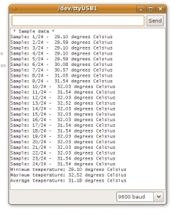
Build a temperature logger. It shall read the temperature once every period of time, for 24 hours. Once it has completed the measurements, it will display the values measured, the minimum, maximum, and average of the temperature data. You can set the time period to be of your own choosing. So let’s have a think about our algorithm. We will need 24 spaces to place our readings (hmm… an array?)

  • Loop around 24 times, feeding the temperature into the array, then waiting a period of time
  • Once the 24 loops have completed, calculate and display the results on an LCD and (if connected) a personal computer using the Arduino IDE serial monitor.

I know you can do it, this project is just the sum of previously-learned knowledge. If you need help, feel free to email me or post a comment at the end of this instalment.

To complete this exercise, you will need the following:

  • Your standard Arduino setup (computer, cable, Duemilanove)
  • Water (you need to stay hydrated)
  • Analog Devices TMP36 temperature sensor (Farnell part number 143-8760)
  • 1 little push button
  • 1 x 10k 0.25 W resistor. For use with the button to the arduino
  • breadboard and some connecting wire
  • one LCD display module

And off you go!

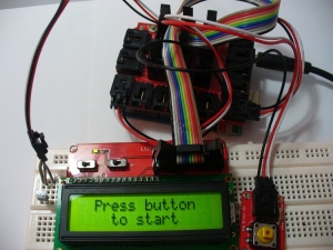
Today I decided to construct it using the Electronic Bricks for a change, and it worked out nicely.

Here is a photo of my setup:

a shot of my serial output on the personal computer:

and of course the ubiquitous video. For the purposes of the demonstration there is a much smaller delay between samples…

(The video clip below may refer to itself as exercise 4.1, this is an error. It is definitely exercise 4.2)

And here is the sketch if you would like to take a peek – Ex 4.2. High resolution photos are available in flickr.

Another week over! I’m already excited about writing the next instalment… Congratulations to all those who took part and built something useful! Please subscribe (see the top right of this page) to receive notifications of new articles.

If you have any questions at all please leave a comment (below). If you would like to showcase your work from this article, email a picture or a link to john at tronixstuff dot com.

You might even win a prize. Don’t forget to check out the range of gear at Little Bird Electronics!

So have fun, stay safe and see you soon for our next instalment!


  • Newsletter

    Sign up for the PlanetArduino Newsletter, which delivers the most popular articles via e-mail to your inbox every week. Just fill in the information below and submit.

  • Like Us on Facebook