Posts | Comments

Planet Arduino

Archive for the ‘power supply’ Category

Every maker should have a bench power supply in their possession, ready to provide whatever voltage a project or particular component requires. But not all bench power supplies are created equal. Some only have a single output, some have a limited voltage range, and some can’t handle much current. In an attempt to eliminate such concerns forever, Doug Domke built “the Beast.”

This is a beefy bench power supply that can easily handle any project an electronics tinkerer is likely to tackle. It has three outputs that can all operate at the same time. Two of them can be set anywhere from 2V to 30V and can supply up to 10A each, at 30V. However, the supply transformer is only rated for 240 watts. If both are pulling the full current, then setting them above 24V would exceed the rating. But that isn’t a situation many people will find themselves in. The third output comes from a 20W supply that can provide 3V to 30V (positive or negative).

The user sets each output’s voltage with a simple potentiometer, but an Arduino Nano monitors the voltage and current of each using the analog input pins. The maximum 30V is far too high for the Arduino to work with directly, so it takes measurements through voltage dividers. With voltage and current readings, the Arduino can then calculate wattage. It displays the information for each output on a dedicated 16×2 character LCD screen, connected via I2C. 

If you’re in need of a robust bench power supply, the Beast may just fit the bill.

The post This beastly DIY bench power supply will satisfy any requirement appeared first on Arduino Blog.

The advent of USB-C and the power delivery (PD) standard have allowed for a single cable to carry both large amounts of data and power for a wide range of devices. So, while looking for a PD-capable power bank for his laptop but only coming across expensive units, Instructables user Toby Chui decided to make his own — with additional improvements, of course.

The design for this custom power bank started with a basic schematic consisting of the LiPo battery, a 60W PD module for handling the negotiations between the board and whatever device might be on the other end, and a display unit for showing current battery information. After soldering together a small piece of perfboard containing a buck converter, voltage divider for voltage measurements, and an ACS712 current sensor, Chui glued the entire assembly onto the back of a UART HMI display. The last component was an Arduino Nano that takes in voltage/current readings and sends them to the display, along with the current voltage being delivered over the USB-C cable and the total power consumption. 

With the electronics finished, Chui modeled and 3D-printed a small case that holds the battery and switch at the base while the screen at the top displays the information. You can read more about this project here on Instructables.

The post This DIY power bank can deliver up to 60W and displays info in real-time appeared first on Arduino Blog.

Economy of scale is a wonderful thing, take the switch-mode power supply as an example. Before the rise of the PC, a decent multi-voltage, high current power supply would be pretty expensive. But PCs have meant cheap supplies and sometimes even free as you gut old PCs found in the dumpster. [OneMarcFifty] decided to make a pretty setup for a PC supply that includes a very nice color display with bargraphs and other niceties. You can see the power supply in action in the video below.

The display is a nice TFT driven by an Arduino Nano. The project uses ACS712 current sensor modules, which are nice Hall effect devices that produce a linear output for current and have over 2 KV of voltage isolation.

There are three current sensors, one for each output. Really what makes this impressive compared to many similar projects is the very nice graphical output. The GitHub has all the software as well as PCB layouts. Of course, you’ll have to adapt the enclosure to your specific power supply, but it should be pretty easy to arrange an enclosure.

With only a few buttons, the user interface is a little clunky, but no more so than a lot of other projects. You essentially only use the buttons to change the speed, scale, and resolution of the bar graphs. The output voltages are fixed and there are no current limits.

Another answer is to find a higher voltage supply and mate it with a cheap power supply module. We’ve also seen non-PC power supplies put in a PC case.

Quick Charge, Qualcomm’s power delivery over USB technology, was introduced in 2013 and has evolved over several versions offering increasing levels of power transfer. The current version — QCv3.0 — offers 18 W power at voltage levels between 3.6 V to 20 V.  Moreover, connected devices can negotiate and request any voltage between these two limits in 200 mV steps. After some tinkering, [Vincent Deconinck] succeeded in turning a Quick Charge 3.0 charger into a variable voltage power supply.

His blog post is a great introduction and walk through of the Quick Charge ecosystem. [Vincent] was motivated after reading about [Septillion] and [Hugatry]’s work on coaxing a QCv2.0 charger into a variable voltage source which could output either 5 V, 9 V or 12 V. He built upon their work and added QCv3.0 features to create a new QC3Control library.

To come to grips with what happens under the hood, he first obtained several QC2 and QC3 chargers, hooked them up to an Arduino, and ran the QC2Control library to see how they respond. There were some unexpected results; every time a 5 V handshake request was exchanged during QC mode, the chargers reset, their outputs dropped to 0 V and then settled back to a fixed 5 V output. After that, a fresh handshake was needed to revert to QC mode. Digging deeper, he learned that the Quick Charge system relies on specific control voltages being detected on the D+ and D- terminals of the USB port to determine mode and output voltage. These control voltages are generated using resistor networks connected to the microcontroller GPIO pins. After building a fresh resistor network designed to more closely produce the recommended control voltages, and then optimizing it further to use just two micro-controller pins, he was able to get it to work as expected. Armed with all of this information, he then proceeded to design the QC3Control library, available for download on GitHub.

Thanks to his new library and a dual output QC3 charger, he was able to generate the Jolly Wrencher on his Rigol, by getting the Arduino to quickly make voltage change requests.


Filed under: Arduino Hacks, hardware

USB chargers are everywhere and it is the responsibility of every hacker to use this commonly available device to its peak potential. [Septillion] and [Hugatry] have come up with a hack to manipulate a USB charger into becoming a variable voltage source. Their project QC2Control works with chargers that employ Quick Charge 2.0 technology which includes wall warts as well as power banks.

Qualcomm’s Quick Charge is designed to deliver up to 24 watts over a micro USB connector so as to reduce the charging time of compatible devices. It requires both the charger as well as the end device to have compatible power management chips so that they may negotiate voltage limiting cycles.

In their project, [Septillion] and [Hugatry] use a 3.3 V Arduino Pro Mini to talk to the charger in question through a small circuit consisting of a few resistors and diodes. The QC2.0 device outputs voltages of 5 V, 9 V and 12 V when it sees predefined voltage levels transmitted over the D+ and D- lines, set by Arduino and voltage dividers. The code provides function calls to simplify the control of the power supply. The video below shows the hack in action.

Quick Charge has been around for a while and you can dig into the details of the inner workings as well as the design of a compatible power supply from reference designs for the TPS61088 (PDF). The patent (PDF) for the Quick Charge technology has a lot more detail for the curious.

Similar techniques have been used in the past and will prove useful for someone looking for a configurable power supply on the move. This is one for the MacGyver fans.


Filed under: Arduino Hacks, hardware

The uninterruptible power supply was once a standard fixture in the small office/home office as a hedge against losing work when the electrons stop flowing from your AC outlet. Somewhat in decline as computing hardware shifts away from dedicated PCs toward tablets, phones and laptops, the UPS still has a lot of SOHO utility, and off-the-shelf AC units are easy to find. But if your needs run more to keeping the electrons flowing in one direction, then you might want to look at [Kedar Nimbalkar]’s programmable DC backup power system.

Built inside a recycled ATX power supply case, [Kedar]’s project is heavy on off-the-shelf components, like a laptop power supply for juice, a buck converter to charge the 12 volt sealed lead acid battery, and a boost converter to raise the output to 19.6 volts. An Arduino and an optoisolator are in charge of controlling the charging cycle and switching the UPS from charging the battery to using it when mains voltage drops.

 If you need a DC UPS but would rather skip the battery, you could try running a Raspberry Pi with electrons stashed in a supercapacitor. Or if you’ve got an aging AC UPS, why not try beefing it up with marine batteries?

[Thanks for the tip, Morris]


Filed under: Arduino Hacks, misc hacks
Dec
16

Powering an Arduino Board from the Environment

arduino, energy harvesting, power supply Comments Off on Powering an Arduino Board from the Environment 

article-2012december-powering-an-arduino-board-fig4

by Publitek European Editors:

Building an Arduino system that harvests energy from the environment provides a significant amount of freedom from wiring, but requires some close attention to the system design. Using power from the environment and wireless links frees up the board from any wiring and gives tremendous flexibility for placing the equipment.

Arduino is an open-source electronics prototyping platform that is specifically optimized for the hobbyist building systems that receive input from sensors. This is particularly appropriate for an energy harvesting design so that sensors can be placed in the right location without having to worry about power and signal wires.

Powering an Arduino Board from the Environment - [Link]

Hello readers

Today you can follow making a simple 5V DC power supply from initial idea to finished product. This is not an exercise in making a flash power supply, just solving a problem with the parts at hand.

When writing my Arduino tutorials, or generally experimenting with the breadboards – and more often both – I have needed 5V DC to power something, or in the case of working with two Arduinos at once, having to run USB cables all around the place just to power them. Some may say “Oh, just get another couple of wall warts/plug packs”. True, but good ones are over Au$20 here… and buying cheap ones have not been so successful in the past. However, I do have a collection of odd-voltage plug packs from old cordless phones and so on.. 12V AC, 15V DC etc. And to be honest, right now the bbbooost project is in pieces in a box as I’ve run out of breadboards at the moment working on other things.

So while at my desk I thought “How can I combine my need for 5V, my cheapness and use one of these plugpacks?”. Easy!

After perusing my stock database it turned out that all the parts were already around me to make a simple 5V supply using an LM7805 voltage regulator. It is quite versatile, can accept voltages up to 35V, and I have some in the drawer. Here is the data sheet: LM7805.pdf.

Following this it occurred to me that it would be nice to not have to worry about the type of current from the plug pack – AC or DC. So my circuit needs a bridge rectifier. That can be made with four 1N4004 diodes. And it would be nice to have a power-on indicator that isn’t a tiny speck of light. Thankfully I bought some 20mm red LEDs when Farnell had a crazy sale last year. Perfect.

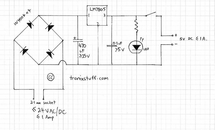
And finally, a nice enclosure. Or anything really, to hold it all together. A small semi-opaque jiffy box was hiding in the cupboard with some veroboard, so they will be used. How? Here is my schematic: (click to enlarge)

Oh – the resistor is 560 ohms. And here are the participants in this project:

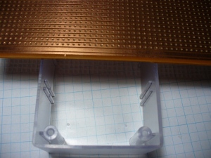
The black stuff at the top-right is heatshrink. The next though was how to mount the board in the box – I don’t have any standoffs, but the box does have some slots to hold the board. So this tells me how much space there is to use on the board, as I will trim it down to fit the space available:

But before hacking things up with the tinsnips, it pays to see if your circuit will actually fit in the board space available. (However my circuit was quite small, so I knew it would fit). This can be done by laying out your parts on a sheet of paper that has a grid of dots at 2.54mm intervals. Next was to measure the internal dimensions of the box in order to cut the veroboard. Then out with the tinsnips and chop chop chop. When using tinsnips or a saw of some sort, try and cut a little outside of the line – as the PCB material does flex a little .This means that you may lose 2~3 mm at the edges, so make allowances for that.

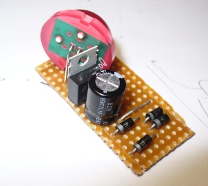
Moving on, I now have the board sized for the box and can start component placement:

The parts just fit in together nicely. I will have to drill the holes for the 7805 regulator so it can fit, however it doesn’t really leave room for the 0.1uF capacitor. However it is not really necessary, the output will be ok without it. The leads from the power socket, and to the switch and output lead will feed from the bottom of the PCB.

Now for one final visual check, and then to solder in the components.

After doing so, then it was time to put the link in and cut the tracks. I use a sanding bit on the drill to cut the tracks, completely removing the copper. :)

After cutting the tracks on the solder side, it was a good time to use the continuity function of the multimeter to check for shorts between tracks and other errors. The soldering proved to be fine, and the track cuts worked. Now it was time to position the DC socket and switch in order to wire them in, then drill their holes. The output wire is to come out of the top:

Now all there is to do is solder the connecting wires from the DC socket to the rear of the circuit board, and the output wire via the switch. At this point the unit was also tested. Naturally my eyesight had failed me and a short had appeared. However it was sorted out with the solder sucker:

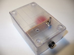
Notice how I tied a know in the output lead before it passes through the lid – this is to stop accidental damage to the board caused by someone pulling the wire out. Here is the finished product, with a nice red glow for a power-available indicator:

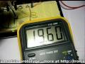
Hooray – finished. What else was there to do on a Tuesday night? The LED indicates power is supplied to the box, and the switch just controls the load. Not too happy about that 5.05V reading… but then again, that meter was somewhat inexpensive.

I hope you enjoyed peering into my electronic life once again. The purpose of this post was more of a confidence-builder than anything, but hopefully someone out there read this and thought “Yes, I can do that”. So go for it!

As always, thank you for reading and I look forward to your comments and so on. Furthermore, don’t be shy in pointing out errors or places that could use improvement. Please subscribe using one of the methods at the top-right of this web page to receive updates on new posts. Or join our new Google Group. High resolution images can be found on flickr.

Otherwise, have fun, be good to each other – and make something! :)


May
02

Greeting again to followers of the bbboost journey. It has been a month since the last instalment, however the 20V DC plug pack took a long time to arrive from the land of China. Nevertheless, the project is moving forward. For my new readers, the bbboost is a power supply that can be assembled by a beginner, and can offer a smooth variable DC output voltage of between ~1.8 and ~20 volts – perfect for experimenting, breadboard, and generally saving money by not buying batteries. You can just make a PCB version, or mount it in an enclosure like a professional desktop unit. No mains voltage wiring is required, so it will fine for the younger enthusiasts. Follow the project from here.

This time I have breadboarded the power supply module, using the circuit described in chapter two.  Let’s have a bit of a look:

These trimpots were ok, but it would be preferable to use the fully enclosed dustproof versions. Will order some and try ‘em out.

One trimpot (the blue and white one) is 5k ohm, – to adjust between the full range, so this is the ‘coarse’ adjuster; the other trimpot is only 500 ohms and changes the voltage selected by the coarse pot by around +/- 1.2 volts. The purpose of having two controls is to make it very easy to select your required voltage down to one-hundredth of a volt. The following video clip is a rough example of this type of adjustment in action:

This power supply will also be designed for installation into a nice enclosure, so in that case one would use normal-sized potentiometers for the coarse and fine voltage adjustment. Will try that for the next instalment.

So,  thank you once more for reading. Please leave feedback and constructive criticism or comments at your leisure… and to keep track, subscribe using the services at the top right of this page!


  • Newsletter

    Sign up for the PlanetArduino Newsletter, which delivers the most popular articles via e-mail to your inbox every week. Just fill in the information below and submit.

  • Like Us on Facebook