The Whiskey Tango Hotel blog looks to simulate the lights of fireworks with a single long strip of NeoPixels, aka WS2812B addressable LEDs.
Fireworks are also pretty cool. On the downside they can be dangerous, scare wildlife, start fires, be expensive, illegal, etc. So, until we can afford our own fleet of drones we settled on this alternative.
The hardware is an ESP8266 and a WS2812B LED-strip with 300 LEDs (16.5 feet). We wanted to use a Arduino Nano (because we had one), but due to the amount of memory needed to define the arrays for the 300 LEDs we went with an ESP8266 (because we had one).
See the video below and the post with Arduino source code.
Humans have domesticated animals since the dawn of time. Dogs (our oldest furry friends) were owned by humans as far back as 30,000 years ago, and since then we’ve formed bonds with all kinds of different creatures.
It was only in the last century, though, that we started to actually build our own pets. The history of robot pets is a short but fascinating one, going from barely recognisable gadgets to incredibly sophisticated devices in just a few decades.
In this article, we’ll look at some of the biggest milestones in the evolution of robotic pets, and show you a few neat examples from the Arduino Project Hub.
A history of robot pets
The Phony Pony
Built in 1968 at the University of Southern California, the Phony Pony marked the beginning of a new era. As the first ever autonomous quadrupedal robot, it is the common ancestor to which all of today’s robot dogs and cats can be traced back (despite being named after a different species).
By today’s standards, the Pony wasn’t all that sophisticated. It featured four legs, each with its own hip and knee joint, attached to a frame. But, it worked — the Pony was able to walk around at various slow speeds. It wasn’t wireless but, come on, it was the ‘60s.
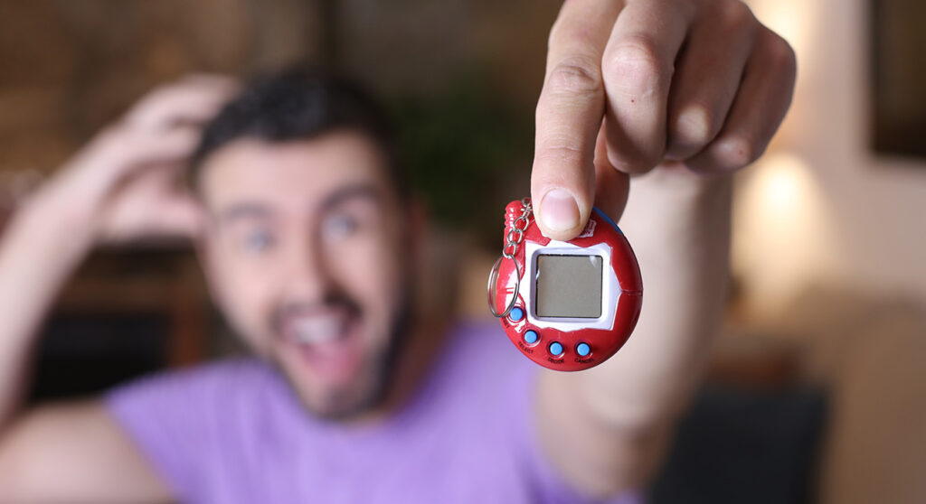
The Tamagotchi
Here’s one for the ‘90s kids. The Tamagotchi, released in 1996 in Japan by Bandai, soon made its way to the rest of the world. This simple, handheld device containing an animated pet which needed to be fed, watered, and cared for like any living animal soon became a smash hit — selling over 80 million units to date.
Anyone who has been through the traumatizing experience of losing their Tamagotchi will testify that these bundles of pixels can inspire surprising amounts of love and devotion from their owners.
The Furby
Another ‘90s classic here — the robotic, furry Furbies were popular throughout the world and sold more than 40 million units. While they weren’t the pinnacle of sophistication in terms of what they could actually do, it’s clear that people enjoyed the novelty of a robotic pet that was, in some small way, kind of alive.
BigDog
Released in 2005, the BigDog was the debut project of the now-famous robotics company Boston Dynamics. The BigDog was designed to be used in the military, and is equipped to do tasks like move easily over challenging terrain and carry up to 154 kg of weight.
Unfortunately, in spite of its physical prowess, the BigDog never quite made the cut, as its engine was deemed to be too noisy to be effectively used in combat situations. However, since then Boston Dynamics have been refining and optimizing their robot war dogs, and the latest iterations look very fearsome indeed.
Pleo the Dinosaur
UGOBE, based in California, set out to build a robotic creature that was also imbued with its own operating system, giving it an uncanny resemblance to a living thing. The result was Pleo — a pet dinosaur that uses cutting-edge research in fields like robotics, sociology, and even philosophy to appear very life-like indeed.
ANYmal Robotic Dog
Developed by Swiss robotics company ANYbotics, the ANYmal Robotic Dog was designed to safely inspect unsafe industrial environments. It comes equipped with an arsenal of tools like laser inspection sensors and the ability to autonomously navigate through different environments, collecting and sharing an impressive amount of data.
Make your own
Inspired by the idea of building your very own robotic pet? The Arduino Project Hub has a number of examples from people who have tried their hands at just that. Let’s take a look at a few.
The Nerd
Built in the same mold as the Tamagotchi, The Nerd is an electronic pet that lives in your pocket (or wherever you put it down) and survives by eating WiFi SSIDs (it also needs rest and sunlight).
To properly care for your Nerd, you need to make sure it has just the right balance of offline and online mode, along with sufficient levels of light and darkness. If it’s disconnected from that tasty WiFi for too long, The Nerd will emit a desperate plea in Morse code,
You can build your own Nerd using the Arduino MKR IoT Bundle, a few other components like an RGB LED, phototransistor, and buzzer, and some code. Just make sure it doesn’t go too hungry — The Nerd makes a lot of noise when it dies. And you can now create your own Nerd with just one click with the ready-to-use The Nerd Arduino Cloud template. Read the full tutorial to learn more about how to use it.
Roger Bot
Arduino user hannu_hell built the Roger Bot in their very own home using an Arduino and a few other components. The Roger Bot features a robotic arm and the ability to move around on flat surfaces. It also contains built-in sensors that collect sensory data and display them on an LCD screen.
While it isn’t well-equipped to handle uneven or challenging terrain just now, this is something hannu_hell is working on for the future.
Build your own with Arduino
With an Arduino, a few simple components, and a free subscription to the Arduino Cloud, you too can create your very own robotic pet. Add to the ranks of historical robotic companions and gain a faithful and useful friend. And who knows… with the way AI is developing, maybe a truly autonomous robot pet is only just around the corner.
Pest monitoring is essential for the proper management of any vineyard as it allows for the early detection and management of any potential pest infestations. By regularly monitoring the vineyard, growers can identify pests at early stages and take action to prevent further damage. Monitoring can also provide valuable data on pest behaviour, seasonality, and population size. This information can be used to adjust management strategies and protect the quality of grapes harvested from the vineyard.
One of the most effective ways to monitor pests is with pheromone traps. Pheromone traps use synthetic hormone-like compounds to attract specific insects and correctly estimate their overall presence based on their number, preventing major damage and disease to the plants. Using pheromone traps can help protect vines from serious infestations, reduce pesticide use, and ensure a healthy crop. Additionally, these traps can be used to track the activity of a particular species over time which is useful for predicting when pest populations are likely to peak or decline. By knowing when insect pressure is high or low, winemakers can better plan for treatments and cultivate their land accordingly.
The value of conservation and pest control initiatives is immeasurable as the effects of climate change, biodiversity loss, and species invasions become more evident. Traps are widely used for population detection, tracking progress on projects, determining management solutions; in addition to assessing treatment performance.
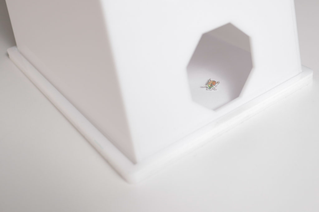
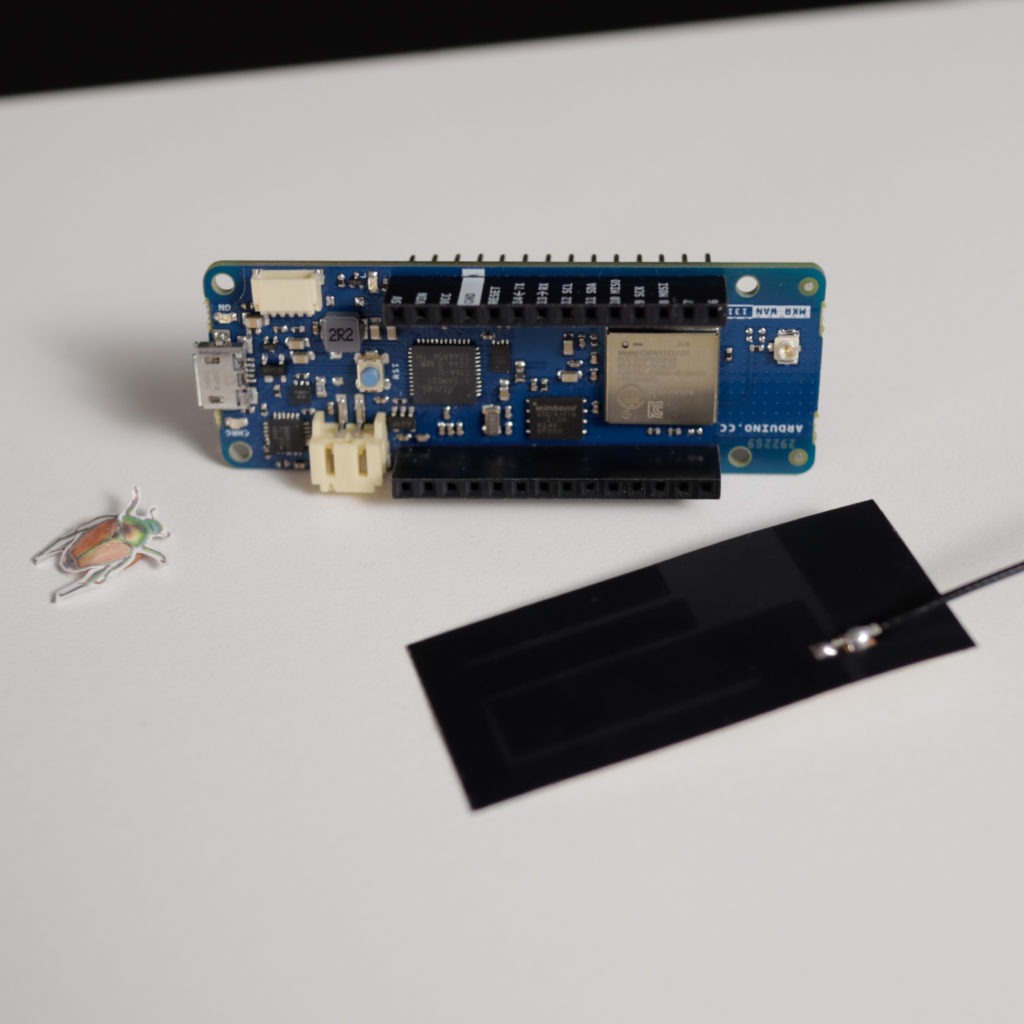
Popillia japonica
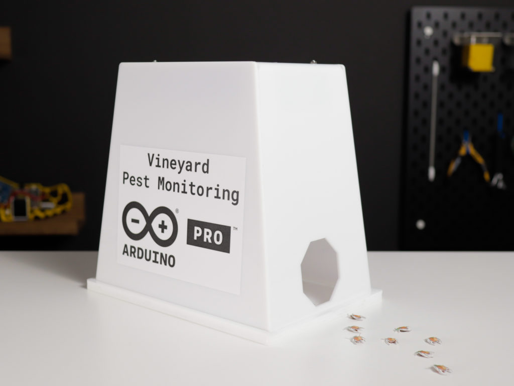
Vineyard Pest Monitoring is the practice of monitoring and controlling vineyard pests, such as Popillia japonica. Popillia japonica is a species of scarab beetle native to Japan that feeds on grapevine leaves and can cause significant damage in vineyards. Traditional pest management techniques involve manual monitoring with traps or pheromone traps. These methods are labor-intensive and may not provide accurate and timely monitoring or pest control.
Our solution
We propose a solution for estimating Popillia japonica populations in vineyards using pheromone traps and Computer Vision.
This system utilizes LoRa® technology to enable remote monitoring of Popillia japonica in vineyards. Arduino Pro allows farmers to monitor Popillia japonica activity with pheromone traps and collect the data remotely. This makes it easier for farmers to detect infestations early and take action, leading to improved efficiency and higher yields. The IoT technology also helps reduce labor costs associated with manual monitoring.
By using Computer Vision in combination with LoRa® technology, real-time data of pest activity can be collected. This information allows growers to better understand the dynamics of Vineyard pests such as Popillia japonica, helping them to make more informed decisions and reduce their environmental impact. With the right monitoring tools, vineyards can now be better prepared to face the increased risk of Japanese beetle outbreaks posed by climate change. With IoT devices, there is no longer any excuse not to employ pest monitoring in vineyards. The use of IoT-based pest monitoring is not only cost-effective, but also helps to reduce the environmental impact of pesticide applications. This makes it an important tool for vineyard managers looking to protect their crops in an ever-changing environment. The future of vineyard management lies in the hands of innovative technologies like this one, enabling farmers to ensure their crops are healthy and safe. By taking advantage of the latest technologies, vineyard managers can make sure their crops are protected from infestations and ensure a successful harvest season year after year.
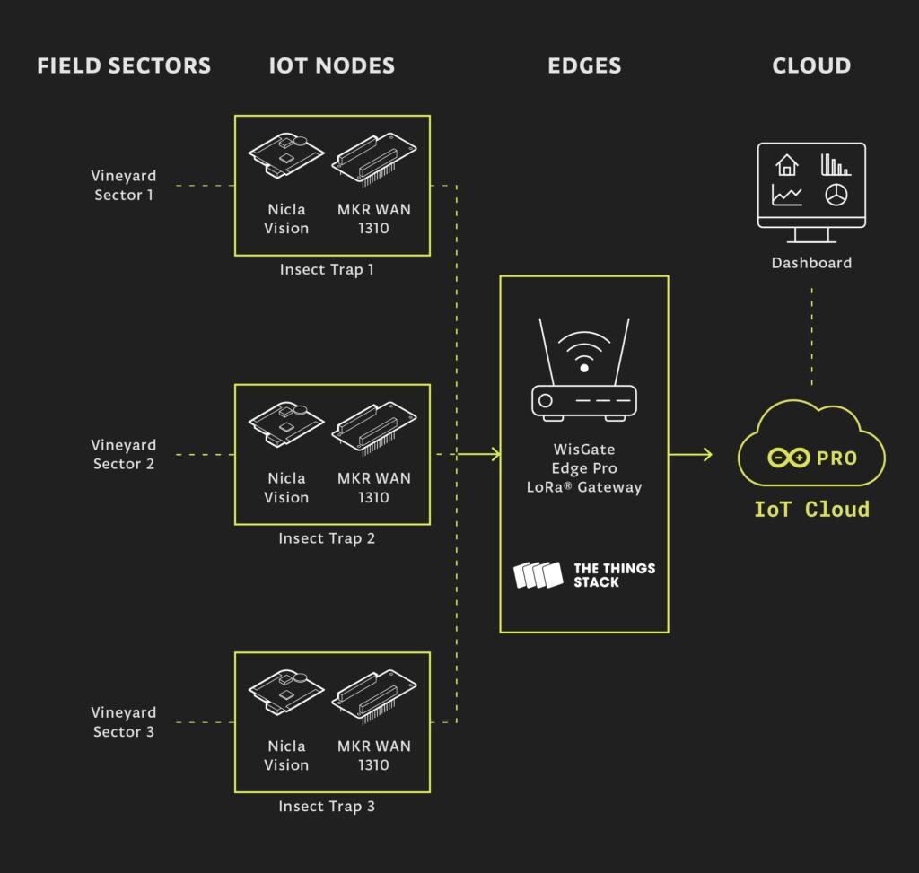
To address the challenge we will devise a pest monitoring system based on sensor nodes that monitor areas in the vineyard and send the collected data to a LoRa® gateway that can either display it locally or push it toward a cloud solution where further computation can be done. Either at the gateway level or in the cloud, alerts can be set based on certain thresholds considered relevant.
Bug counting
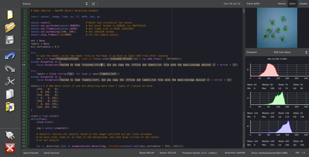
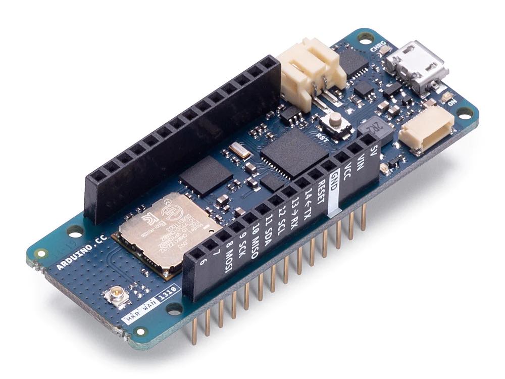
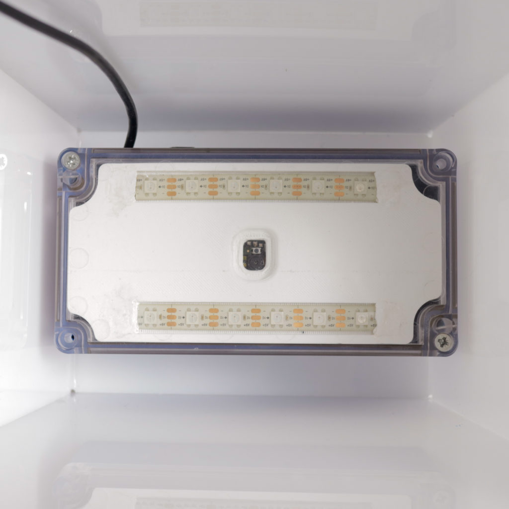
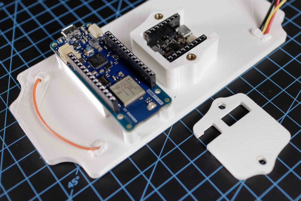
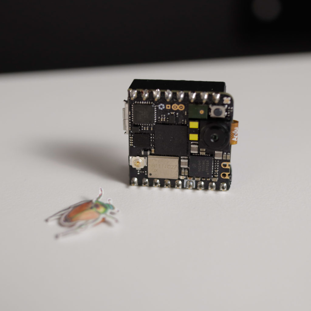
For monitoring the number of Popillia Japonica in each section of the vineyard we have chosen the Arduino Nicla Vision which is ideal for this project because of its advanced image processing capabilities. It combines a powerful Dual ARM® Cortex® M7/M4 IC processor with a 2MP color camera that supports TinyML in a compact format. The full datasheet is available here. For training the object detection model, we have chosen the Edge Impulse platform where we can easily train and deploy a model that will allow us to detect the number of bugs in the view of the camera. After the deployment, no further need of internet connectivity is needed for the camera and only the number of bugs will be relayed to the Arduino MKR WAN 1310 through UART.
Connectivity
The Arduino MKR WAN 1310 is a powerful and versatile IoT development board based on the ARM Cortex®-M0+ 32-bit processor, perfect for building connected projects. It supports the LoRa® communication protocol, making it suitable for long-range applications such as vineyard pest monitoring. Moreover, it also supports the UART, I2C, and SPI communication protocols so it can easily be interfaced with other devices. Additionally, the MKR WAN 1310 features an integrated LiPo battery charger to keep your project running 24/7. With its compact size and low energy consumption, this board can be used in a wide range of projects where connectivity is required without sacrificing power efficiency.
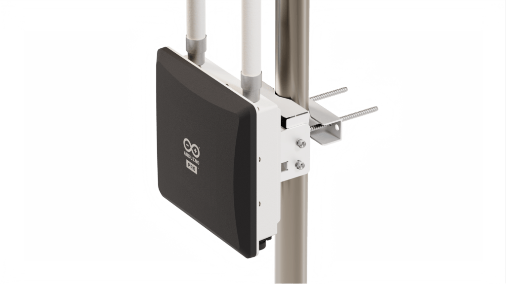
Thanks to its radio connectivity via LoRa® radio transceivers, the data can be sent directly to the nearest LoRa® gateway which forwards it to the Arduino IoT Cloud. The gateway, Arduino Pro WisGate Edge Pro powered by RAKwireless ensures secure and reliable connectivity for a wide range of professional applications and is suitable for medium-sized to wide area coverage in industrial environments and remote regions. Its high transmission power and 2x fiberglass antennas with 5dBi gain provide extensive coverage in open environments, making it the perfect fit for IoT commercial outdoor deployment – required for example for parking sensors, remote fleet management, livestock tracking and geofencing, and soil monitoring solutions that maximize crops’ yield.
Solving it with Arduino Pro
Now let’s explore how we could put all of this together and what we would need for deployment both in terms of hardware and software stack. The Arduino Pro ecosystem is the latest generation of Arduino solutions bringing users the simplicity of integration and scalable, secure, professionally supported services.
The Nicla Vision has been programmed in MicroPython since the Edge Impulse model was created/tested using the OpenMV IDE and thus we have also sent the number of detected bugs to the Arduino MKR WAN 1310 via UART.
The Arduino MKR WAN 1310 has been programmed in C/C++ using the Arduino IDE and the Arduino IoT Cloud and registered ontheThe Things Stack(TTS)platform. The Arduino MKR WAN 1310 acts as an end device programmed to receive the number of detected Popilia Japonica bugs from the Nicla Vision through UART and forward it to the Arduino IoT Cloud through the nearest LoRa® gateway connected to the TTS service.
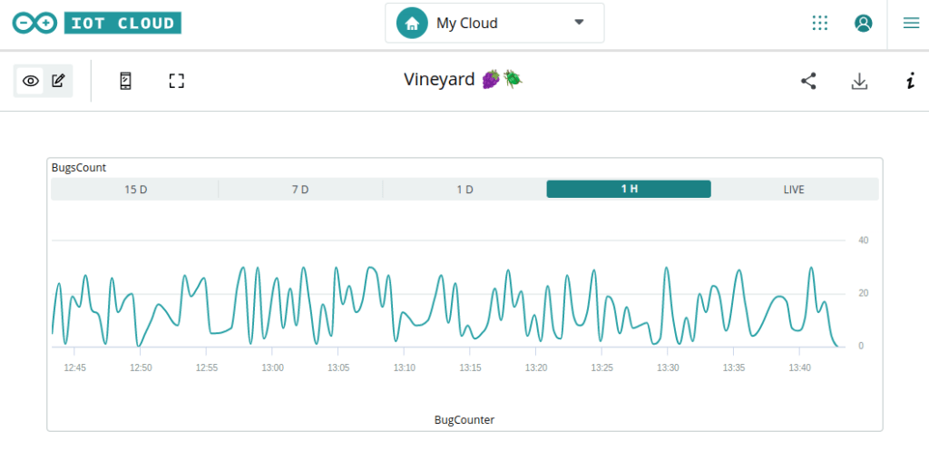
Here is a screenshot from a dashboard created directly in the Arduino IoT Cloud showcasing data received from the sensor nodes:
Here is an overview of the software stack and how a minimum deployment with one of each hardware module communicates to fulfill the proposed solution:
Conclusion
By combining Computer Vision with LoRa® technology, farmers can create a reliable vineyard pest monitoring system that is capable of estimating the population of Popillia japonica quickly and accurately. With this IoT-based op-solution, farmers can monitor Popillia japonica activity in their vineyard and take action before Popillia japonica causes significant damage. This helps protect the vineyard from Popillia japonica infestations and ensures higher yields for the farmer. With Vineyard Pest Monitoring with Arduino Pro, farmers no longer need to rely on labor-intensive manual methods for Popillia japonica monitoring. Instead, they can use IoT technology to create an efficient and cost-effective pest monitoring system that provides accurate data about Popillia japonica activity in their vineyards.
In summary, pheromone traps are an important tool for protecting vineyards from pests and ensuring a healthy harvest season and great wines. Salute!
Our smartphones go pretty much everywhere with us, and we use them for more things than we even realize. From literally the very moment we’re startled into life in the morning, until the one final doom scroll through social media before bed, our phones are with us.
It makes sense, then, to think about ways to connect your smartphone to your Arduino projects, adding another layer of user-friendliness and convenience. In this article, we’ll take a look at some of the best tips and hacks for bringing your phone and your home automation projects closer together, and we’ll share some examples from the Arduino community. Arduino Cloud is the perfect companion for building automated projects, and the IoT Cloud Remote mobile app makes things a lot easier. In this article we’ll see some companion apps and you can check out more compatible projects in our Home Automation website.
Use the iRobbie app
The iRobbie app is designed specifically to connect your smartphone to your Arduino projects. It’s actually a fairly simple concept, using Bluetooth to connect your phone to the Arduino board. Once connected, you can access a ton of features like object recognition and tracking, all via the phone’s camera. iRobbie allows your Arduino projects to recognise and track over 60 objects.
You can learn more about iRobbie and how to get started with it here.
Notification IoT Using NeoPixel and Smartphone
If there’s one thing phones are good for, it’s receiving updates. But what about when you miss important updates? What about when your phone is on the other side of the room, or the TV is playing loud, or you just missed that vibration?
Speaking of vibrations, wouldn’t it be cool if there were a slightly less annoying way to get notifications from your phone?
Well, step forward Arduino user notiduin, who used NeoPixel and Arduino to find a solution. This project allows you to get notifications in the form of LED lights of different colours. By combining HC-06 Bluetooth, Arduino Uno, Neo Pixel and an Android App, it’s possible to have all your phone’s notifications sent to an Arduino where they can turn on different colours of LED.
You can even assign a certain colour to each type of notification. For example, a Facebook notification can light up the blue LED, an SMS message can trigger the yellow light, and a new email can cause the red light to flash — it’s entirely up to you. The project works with any of the apps on your smartphone.
Getting the perfect smartphone photo can be a tougher task than it first appears. Stores across the world now have their shelves lined with tripods, stands, and other gadgets to make snapping that perfect shot more manageable than ever… but sometimes you just need to take matters into your own hands.
That’s what Reddit user u/careyi4 did. He 3D-printed his very own smartphone camera slider, powered by an Arduino, to make it easier than ever to line up pro-level smartphone photoshoots. Check out the video for more information.
Make any Arduino smartphone-controlled with just a few lines of code
You don’t need to be a programming genius to make your own Arduino projects smartphone-controlled. Reddit user u/TylerTimoj used just a few lines of simple code to make their projects easily controlled from their smartphone, and anyone can emulate it.
You can check out the full project here, along with a video where u/TylerTimoj shows you how it’s done.
Did you know that your phone is an IoT device?
The Arduino IoT Remote app (available for Android and iOS) was created to enable you to remotely manage and monitor your devices through the Arduino Cloud dashboards, offering complete control at your fingertips from anywhere you are. Arduino has gone a BIG step further and enabled you to use the app as an IoT device, utilizing some of the sensors in your mobile phone such as accelerometer, GPS, microphone, compass or barometer to collect data and transmit it to the Arduino Cloud. This feature automatically creates in the Arduino Cloud everything needed to monitor the sensors (the Device, the Thing and a dashboard) and share the data with other devices.
Starting to play with real hardware can be tricky for non-experienced users, so this feature enables users to get familiar with the Arduino Cloud device management environment using their own phone. Easy, right?
But you can also use the data from your phone sensors in your projects. Imagine the endless possibilities using that information. For instance, you can use virtual geographic boundaries for geofencing to initiate actions based on your location. You can also automate home-based tasks such as turning off lights when you depart and turning them on when you return, securing doors, and adjusting home climate control. Moreover, you can track your loved ones with geofencing and receive immediate notifications if they leave a designated area. The accelerometer in your phone can also be utilized to detect accidents or falls, and you can even use your phone as a remote control for games or robots.
Only your imagination sets the boundaries of what you can do with this new feature.
If you want to learn more about the “Phone as Device” feature, don’t miss this article on the documentation.
Unlock a whole new side to your smartphone
With Arduino, a few basic components, and a bit of knowledge, anyone can bring entirely new capabilities to their smartphone and start doing a whole range of new tasks with it. I mean, if it’s going to be with you all day, you might as well get as much out of it as possible, right?
After the successful launch of the new Project Hub at the end of last year, we are ready for a new challenge and the opportunity for you to be rewarded for your awesome work.
Starting February 1st, we are launching a new ‘Arduino Project of the Month’ competition for everyone in our community.
Simply share your best project on the new Project Hub.
Every month, our team will then select up to three projects and their creators will receive fabulous gifts!
First selected will receive a gift card worth $500.
Second selected will receive a gift card worth $300
Third selected will receive a gift card worth $100.
(Gift cards can only be redeemed on the Arduino Store.)
We will officially start considering projects uploaded after February 1, 2023.
Please keep in mind the general rules to enter the competition:
All the participants must be 18+ years of age.
All projects accepted for Project Hub will be evaluated by the Arduino Team. If your project is shortlisted you will be contacted with further instructions.
Please make sure that you are uploading your project using your Arduino account. Projects submitted using Hackster.io accounts will not be accepted.
The Arduino team will evaluate the projects based on the quality of the project itself, not on the number of projects a user updates. But obviously the more projects you add, the more you increase your chances of being selected.
Projects submitted by companies won’t be considered part of this competition.
The Arduino Team is solely responsible for monthly selection(s). Each selection is final and will not be amended.
Projects can only be submitted to the challenge once. It is not permitted to delete a project and then re-submit it again in the following month(s).
So, what are you waiting for? Upload your project on the new Arduino Project Hub for a chance to receive a $500 gift card to help make your next project even more amazing!
The UNO wasn’t Arduino’s first board, and it won’t be its last. There have been many varieties of microcontroller and maker boards before and after the UNO, but none have been as iconic. As we cross the epic milestone of 10 million UNOs sold and the launch of the UNO Mini Limited Edition, we decided it was time to take a look back at some of our favorite UNO projects from the last 10 years.
And we want to hear about yours, too. Join us over on social media to share your favorite UNO projects, whether you built them yourself or marveled at someone else’s electronic creation.
The Toothbrush Machine
The queen of terrible tech Simone Giertz casually blew the internet’s mind back in 2015 with her robotic skateboard helmet with an automated toothbrush mounted on the front.
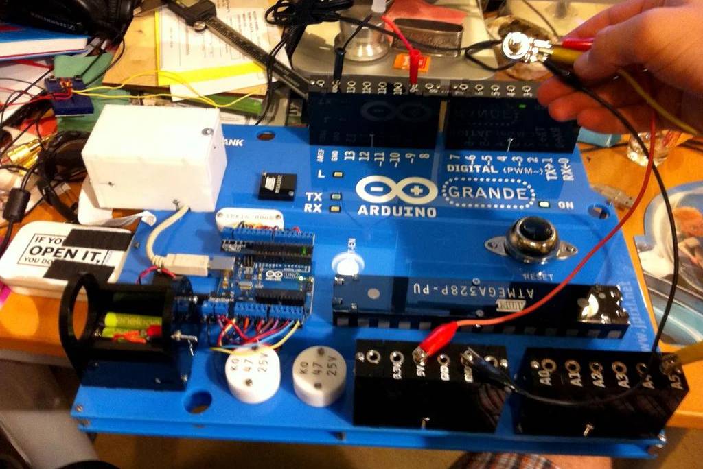
Arduino GRANDE
Spend more than five minutes Googling “Arduino UNO” and you’re bound to find yourself looking at the Arduino GRANDE. A fully operational UNO that’s six time bigger than it should be.
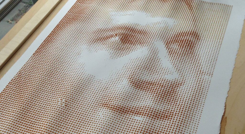
Coffee Printer
If you’ve ever left a coffee ring on your notepad or table top, you’ll appreciate how effective it is at leaving a mark. This UNO project put that annoying side effect of coffee to artistic use.
Autonomous “Follow Me” Cooler
Why carry your own beer and sandwiches around like a sucker, when you can “simply” connect a robotic cooler to your smartphone’s Bluetooth, hook it up with GPS and let if follow you around.
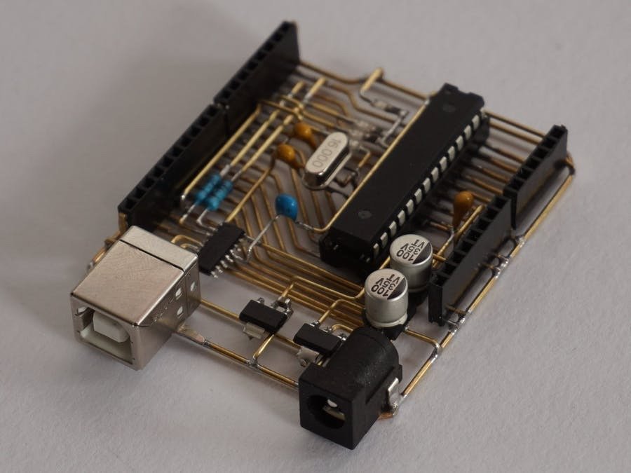
Skeleton Arduino Uno
This Arduino UNO is its own project, which is so meta it’s impossible not to love it! It’s a PCB without the PCB, and takes “open” source more literally than any other maker board has ever achieved.
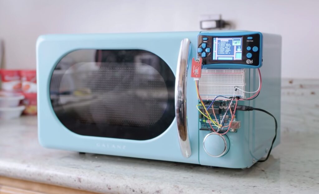
Gaming Microwave
Microwave’s used to be considered the fastest way to cook things. But in today’s CPA-addled world, even one-minute noodles take too long. Problem solved; game while you’re waiting.
Floppotron
This UNO project takes the concept of “everything is a drum” to new levels by turning devices like hard drives, floppy drives, scanners and more into a techno-orchestra.
pedalSHIELD UNO
This programmable guitar pedal built from an UNO lets you create all your own effects and digital sounds, with an ever-growing repository of pre-built effects from the Arduino music community.
Automated Dust Collection
Master maker and craftsman I Like to Make Stuff has created some incredible carpentry projects, and underneath it all is an Arduino UNO keeping his awesome workshop clean.
Useless Box
Useless machines are a wonderful maker project rabbit hole to fall down. This is a great example, and even though they’re useless, you can learn so much from building one. Which means it’s not actually useless, right?
Drumcube
Drumcube is a drummer in a box, so as long as you’ve got an Arduino UNO and a small box, you’ll always have someone down in the boiler room when you play at a gig.
Petoi Bittle
This highly maneuverable little palm-sized robot runs, jumps and plays to become your very own robotic pet. Some stunning design work, and it can even carry up to half a kilogram as it skips around!
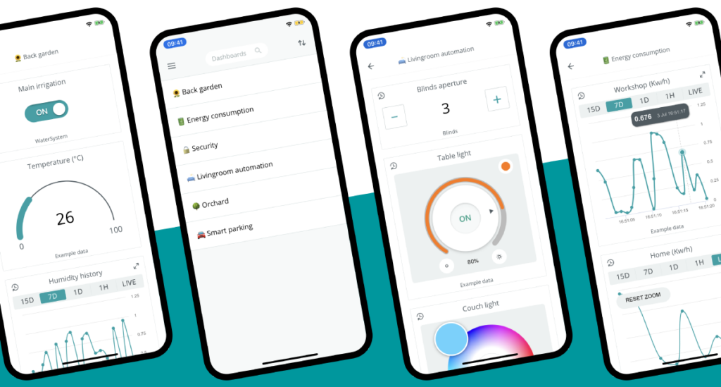
The perfect companion to the Arduino IoT Cloud! Develop your IoT solution online via a desktop, then monitor and control your dashboards on your mobile with the new Arduino IoT Cloud Remote app.
Initially available for free for iPhone on the App Store (Android to follow in the next few weeks), the Arduino IoT Cloud Remote app gives you with the ability to access, monitor or control your IoT projects regardless of the time or place:
In the field: you can read the data from your soil sensors or start your irrigation system directly from anywhere.
In the factory: constant visibility of the state of your manufacturing process status, with the ability to control your automation remotely.
In the home: monitor your home automation systems, check your previous or actual energy consumption from the convenience of your sofa.
The latest dashboard for the Arduino IoT Cloud comes with a host of enhanced features. Creating your dashboard via a desktop or tablet is quick and easy. The tool automatically configures your devices (including the secure crypto element) and automatically generates the main code for your project, making setup as straightforward as possible. A broad set of simple widgets to connect to the properties provides maximum versatility and enables you to set up a new dashboard in minutes.
Your dashboards, how you like them — all dashboards are fully customizable, it’s possible to group devices and organize them in any sequence — just drag and drop to arrange the layout, and select from multiple options including graphs to visualize the data. You can gather and display data from multiple IoT devices in one dashboard, and control those devices as required through your dashboard to fully integrate your solution.
The addition of the Arduino IoT Cloud Remote app to access, monitor, and control dashboards on the go via your phone is the final piece of the jigsaw.
[Alex] needed a project for his microcomputer circuits class. He wanted something that would challenge him on both the electronics side of things, as well as the programming side. He ended up designing an 8 by 16 grid of LED’s that was turned into a game of Tetris.
He arranged all 128 LED’s into the grid on a piece of perfboard. All of the anodes were bent over and connected together into rows of 8 LED’s. The cathodes were bent perpendicularly and forms columns of 16 LED’s. This way, if power is applied to one row and a single column is grounded, one LED will light up at the intersection. This method only works reliably to light up a single LED at a time. With that in mind, [Alex] needed to have a very high “refresh rate” for his display. He only ever lights up one LED at a time, but he scans through the 128 LED’s so fast that persistence of vision prevents you from noticing. To the human eye, it looks like multiple LED’s are lit up simultaneously.
[Alex] planned to use an Arduino to control this display, but it doesn’t have enough outputs on its own to control all of those lights. He ended up using multiple 74138 decoder/multiplexer IC’s to control the LED’s. Since the columns have inverted outputs, he couldn’t just hook them straight up to the LED’s. Instead he had to run the signals through a set of PNP transistors to flip the logic. This setup allowed [Alex] to control all 128 LED’s with just seven bits, but it was too slow for him.
His solution was to control the multiplexers with counter IC’s. The Arduino can just increment the counter up to the appropriate LED. The Arduino then controls the state of the LED using the active high enable line from the column multiplexer chip.
[Alex] wanted more than just a static image to show off on his new display, so he programmed in a version of Tetris. The controller is just a piece of perfboard with four push buttons. He had to work out all of the programming to ensure the game ran smoothly while properly updating the screen and simultaneously reading the controller for new input. All of this ran on the Arduino.
Can’t get enough Tetris hacks? Try these on for size.
Building hardware is exciting because you get to interact with the "real world". In this project you will use the LightBlue Bean to receive notifications from Facebook and Twitter
A few weeks ago I was asked about creating a musical-effect display with an RGB LED cube kit from our friends over at Freetronics, and with a little work this was certainly possible using the MSGEQ7 spectrum analyzer IC. In this project we’ll create a small add-on PCB containing the spectrum analyzer circuit and show how it can drive the RGB LED cube kit.
You can get the bare MSGEQ7 ICs from Sparkfun and the other usual suspects. It never hurts to have a spare one, so order two and matching IC sockets. Finally you should be able to translate a simple circuit to prototyping board.
The circuit
The LED cube already has an Arduino Leonardo-compatible built in to the main PCB, so all you need to do is build a small circuit that contains the spectrum analyzer which connects to the I/O pins on the cube PCB and also has audio input and output connections. First, consider the schematic:
For the purposes of this project our spectrum analyzer will only display the results from one channel of audio – if you want stereo, you’ll need two! And note that the strobe, reset and DCOUT pins on the MSGEQ7 are labelled with the connections to the cube PCB. Furthermore the pinouts for the MSGEQ7 don’t match the physical reality – here are the pinouts from the MSGEQ7 data sheet (.pdf):
The circuit itself will be quite small and fit on a small amount of stripboard or veroboard. There is plenty of room underneath the cube to fit the circuit if so desired:
With a few moments you should be able to trace out your circuit to match the board type you have, remember to double-check before soldering. You will also need to connect the audio in point after the 1000 pF capacitor to a source of audio, and also pass it through so you can connect powered speakers, headphones, etc.
One method of doing so would be to cut up a male-female audio extension lead, and connect the shield to the GND of the circuit, and the signal line to the audio input on the circuit. Or if you have the parts handy and some shielded cable, just make your own input and output leads:
Be sure to test for shorts between the signal and shield before soldering to the circuit board. When finished, you should have something neat that you can hide under the cube or elsewhere:
Double-check your soldering for shorts and your board plan, then fit to the cube along with the audio source and speakers (etc).
Arduino Sketch
The sketch has two main functions – the first is to capture the levels from the MSGEQ7 and put the values for each frequency band into an array, and the second function is to turn on LEDs that represent the level for each band. If you’ve been paying attention you may be wondering how we can represent seven frequency bands with a 4x4x4 LED cube. Simple – by rotating the cube 45 degrees you can see seven vertical columns of LEDs:
So when looking from the angle as shown above, you have seven vertical columns, each with four levels of LEDs. Thus the strength of each frequency can be broken down into four levels, and then the appropriate LEDs turned on.
After this is done for each band, all the LEDs are turned off and the process repeats. For the sake of simplicity I’ve used the cube’s Arduino library to activate the LEDs, which also makes the sketch easier to fathom. The first example sketch only uses one colour:
// Freetronics CUBE4: and MSGEQ7 spectrum analyser
// MSGEQ7 strobe on A4, reset on D5, signal into A0

#include "SPI.h"
#include "Cube.h"
Cube cube;

int res = 5; // reset pins on D5
int left[7]; // store band values in these arrays
int band;

void setup()
{
  pinMode(res, OUTPUT); // reset
  pinMode(A4, OUTPUT); // strobe
  digitalWrite(res,LOW);
  digitalWrite(A4,HIGH);
  cube.begin(-1, 115200);
  Serial.begin(9600);
}

void readMSGEQ7()
// Function to read 7 band equalizers
{
  digitalWrite(res, HIGH);
  digitalWrite(res, LOW);
  for(band=0; band <7; band++)
  {
    digitalWrite(A4,LOW); // strobe pin on the shield - kicks the IC up to the next band
    delayMicroseconds(30); //
    left[band] = analogRead(0); // store band reading
    digitalWrite(A4,HIGH);
  }
}

void loop()
{
  readMSGEQ7();

  for (band = 0; band < 7; band++)
  {
    // div each band strength into four layers, each band then one of the odd diagonals

    // band one ~ 63 Hz
    if (left[0]>=768) {
      cube.set(3,3,3, BLUE);
    }
    else
      if (left[0]>=512) {
      cube.set(3,3,2, BLUE);
    }
    else
      if (left[0]>=256) {
      cube.set(3,3,1, BLUE);
    }
    else
      if (left[0]>=0) {
      cube.set(3,3,0, BLUE);
    }

    // band two ~ 160 Hz
    if (left[1]>=768)
    {
      cube.set(3,2,3, BLUE);
      cube.set(2,3,3, BLUE);
    }
    else
      if (left[1]>=512)
      {
        cube.set(3,2,2, BLUE);
        cube.set(2,3,2, BLUE);
      }
      else
        if (left[1]>=256)
      {
        cube.set(3,2,1, BLUE);
        cube.set(2,3,1, BLUE);
      }
      else
        if (left[1]>=0)
      {
        cube.set(3,2,0, BLUE);
        cube.set(2,3,0, BLUE);
      }

    // band three ~ 400 Hz
    if (left[2]>=768)
    {
      cube.set(3,1,3, BLUE);
      cube.set(2,2,3, BLUE);
      cube.set(1,3,3, BLUE);
    }
    else
      if (left[2]>=512)
      {
        cube.set(3,1,2, BLUE);
        cube.set(2,2,2, BLUE);
        cube.set(1,3,2, BLUE);
      }
      else
        if (left[2]>=256)
      {
        cube.set(3,1,1, BLUE);
        cube.set(2,2,1, BLUE);
        cube.set(1,3,1, BLUE);
      }
      else
        if (left[2]>=0)
      {
        cube.set(3,1,0, BLUE);
        cube.set(2,2,0, BLUE);
        cube.set(1,3,0, BLUE);
      }

    // band four ~ 1 kHz
    if (left[3]>=768)
    {
      cube.set(3,0,3, BLUE);
      cube.set(2,1,3, BLUE);
      cube.set(1,2,3, BLUE);
      cube.set(0,3,3, BLUE);
    }
    else
      if (left[3]>=512)
      {
        cube.set(3,0,2, BLUE);
        cube.set(2,1,2, BLUE);
        cube.set(1,2,2, BLUE);
        cube.set(0,3,2, BLUE);
      }
      else
        if (left[3]>=256)
      {
        cube.set(3,0,1, BLUE);
        cube.set(2,1,1, BLUE);
        cube.set(1,2,1, BLUE);
        cube.set(0,3,1, BLUE);
      }
      else
        if (left[3]>=0)
      {
        cube.set(3,0,0, BLUE);
        cube.set(2,1,0, BLUE);
        cube.set(1,2,0, BLUE);
        cube.set(0,3,0, BLUE);
      }

    // band five  ~ 2.5 kHz
    if (left[4]>=768)
    {
      cube.set(2,0,3, BLUE);
      cube.set(1,1,3, BLUE);
      cube.set(0,2,3, BLUE);
    }
    else
      if (left[4]>=512)
      {
        cube.set(2,0,2, BLUE);
        cube.set(1,1,2, BLUE);
        cube.set(0,2,2, BLUE);
      }
      else
        if (left[4]>=256)
      {
        cube.set(2,0,1, BLUE);
        cube.set(1,1,1, BLUE);
        cube.set(0,2,1, BLUE);
      }
      else
        if (left[4]>=0)
      {
        cube.set(2,0,0, BLUE);
        cube.set(1,1,0, BLUE);
        cube.set(0,2,0, BLUE);
      }

    // band six   ~ 6.25 kHz
    if (left[5]>=768)
    {
      cube.set(1,0,3, BLUE);
      cube.set(0,1,3, BLUE);
    }
    else
      if (left[5]>=512)
      {
        cube.set(1,0,2, BLUE);
        cube.set(0,1,2, BLUE);
      }
      else
        if (left[5]>=256)
      {
        cube.set(1,0,1, BLUE);
        cube.set(0,1,1, BLUE);
      }
      else
        if (left[5]>=0)
      {
        cube.set(1,0,0, BLUE);
        cube.set(0,1,0, BLUE);
      }

    // band seven  ~ 16 kHz
    if (left[6]>=768)
    {
      cube.set(0,0,3, BLUE);
    }
    else
      if (left[6]>=512)
      {
        cube.set(0,0,2, BLUE);
      }
      else
        if (left[6]>=256)
      {
        cube.set(0,0,1, BLUE);
      }
      else
        if (left[6]>=0)
      {
        cube.set(0,0,0, BLUE);
      }
  }
  // now clear the CUBE, or if that's too slow - repeat the process but turn LEDs off
  cube.all(BLACK);
}
… and a quick video demonstration:
For a second example, we’ve used various colours:
// Freetronics CUBE4: and MSGEQ7 spectrum analyser
// MSGEQ7 strobe on A4, reset on D5, signal into A0
// now in colour!

#include "SPI.h"
#include "Cube.h"
Cube cube;

int res = 5; // reset pins on D5
int left[7]; // store band values in these arrays
int band;
int additional=0;

void setup()
{
  pinMode(res, OUTPUT); // reset
  pinMode(A4, OUTPUT); // strobe
  digitalWrite(res,LOW);
  digitalWrite(A4,HIGH);
  cube.begin(-1, 115200);
  Serial.begin(9600);
}

void readMSGEQ7()
// Function to read 7 band equalizers
{
  digitalWrite(res, HIGH);
  digitalWrite(res, LOW);
  for(band=0; band <7; band++)
  {
    digitalWrite(A4,LOW); // strobe pin on the shield - kicks the IC up to the next band
    delayMicroseconds(30); //
    left[band] = analogRead(0) + additional; // store band reading
    digitalWrite(A4,HIGH);
  }
}

void loop()
{
  readMSGEQ7();

  for (band = 0; band < 7; band++)
  {
    // div each band strength into four layers, each band then one of the odd diagonals

    // band one ~ 63 Hz
    if (left[0]>=768) {
      cube.set(3,3,3, RED);
    }
    else
      if (left[0]>=512) {
      cube.set(3,3,2, YELLOW);
    }
    else
      if (left[0]>=256) {
      cube.set(3,3,1, YELLOW);
    }
    else
      if (left[0]>=0) {
      cube.set(3,3,0, BLUE);
    }

    // band two ~ 160 Hz
    if (left[1]>=768)
    {
      cube.set(3,2,3, RED);
      cube.set(2,3,3, RED);
    }
    else
      if (left[1]>=512)
      {
        cube.set(3,2,2, YELLOW);
        cube.set(2,3,2, YELLOW);
      }
      else
        if (left[1]>=256)
      {
        cube.set(3,2,1, YELLOW);
        cube.set(2,3,1, YELLOW);
      }
      else
        if (left[1]>=0)
      {
        cube.set(3,2,0, BLUE);
        cube.set(2,3,0, BLUE);
      }

    // band three ~ 400 Hz
    if (left[2]>=768)
    {
      cube.set(3,1,3, RED);
      cube.set(2,2,3, RED);
      cube.set(1,3,3, RED);
    }
    else
      if (left[2]>=512)
      {
        cube.set(3,1,2, YELLOW);
        cube.set(2,2,2, YELLOW);
        cube.set(1,3,2, YELLOW);
      }
      else
        if (left[2]>=256)
      {
        cube.set(3,1,1, YELLOW);
        cube.set(2,2,1, YELLOW);
        cube.set(1,3,1, YELLOW);
      }
      else
        if (left[2]>=0)
      {
        cube.set(3,1,0, BLUE);
        cube.set(2,2,0, BLUE);
        cube.set(1,3,0, BLUE);
      }

    // band four ~ 1 kHz
    if (left[3]>=768)
    {
      cube.set(3,0,3, RED);
      cube.set(2,1,3, RED);
      cube.set(1,2,3, RED);
      cube.set(0,3,3, RED);
    }
    else
      if (left[3]>=512)
      {
        cube.set(3,0,2, YELLOW);
        cube.set(2,1,2, YELLOW);
        cube.set(1,2,2, YELLOW);
        cube.set(0,3,2, YELLOW);
      }
      else
        if (left[3]>=256)
      {
        cube.set(3,0,1, YELLOW);
        cube.set(2,1,1, YELLOW);
        cube.set(1,2,1, YELLOW);
        cube.set(0,3,1, YELLOW);
      }
      else
        if (left[3]>=0)
      {
        cube.set(3,0,0, BLUE);
        cube.set(2,1,0, BLUE);
        cube.set(1,2,0, BLUE);
        cube.set(0,3,0, BLUE);
      }

    // band five  ~ 2.5 kHz
    if (left[4]>=768)
    {
      cube.set(2,0,3, RED);
      cube.set(1,1,3, RED);
      cube.set(0,2,3, RED);
    }
    else
      if (left[4]>=512)
      {
        cube.set(2,0,2, YELLOW);
        cube.set(1,1,2, YELLOW);
        cube.set(0,2,2, YELLOW);
      }
      else
        if (left[4]>=256)
      {
        cube.set(2,0,1, YELLOW);
        cube.set(1,1,1, YELLOW);
        cube.set(0,2,1, YELLOW);
      }
      else
        if (left[4]>=0)
      {
        cube.set(2,0,0, BLUE);
        cube.set(1,1,0, BLUE);
        cube.set(0,2,0, BLUE);
      }

    // band six   ~ 6.25 kHz
    if (left[5]>=768)
    {
      cube.set(1,0,3, RED);
      cube.set(0,1,3, RED);
    }
    else
      if (left[5]>=512)
      {
        cube.set(1,0,2, YELLOW);
        cube.set(0,1,2, YELLOW);
      }
      else
        if (left[5]>=256)
      {
        cube.set(1,0,1, YELLOW);
        cube.set(0,1,1, YELLOW);
      }
      else
        if (left[5]>=0)
      {
        cube.set(1,0,0, BLUE);
        cube.set(0,1,0, BLUE);
      }

    // band seven  ~ 16 kHz
    if (left[6]>=768)
    {
      cube.set(0,0,3, RED);
    }
    else
      if (left[6]>=512)
      {
        cube.set(0,0,2, YELLOW);
      }
      else
        if (left[6]>=256)
      {
        cube.set(0,0,1, YELLOW);
      }
      else
        if (left[6]>=0)
      {
        cube.set(0,0,0, BLUE);
      }
  }
  // now clear the CUBE, or if that's too slow - repeat the process but turn LEDs off
  cube.all(BLACK);
}
… and the second video demonstration:
A little bit of noise comes through into the spectrum analyzer, most likely due to the fact that the entire thing is unshielded. The previous prototype used the Arduino shield from the tutorial which didn’t have this problem, so if you’re keen perhaps make your own custom PCB for this project.
Conclusion
Well that was something different and I hope you enjoyed it, and can find use for the circuit. That MSGEQ7 is a handy IC and with some imagination you can create a variety of musically-influenced displays. And while you’re here – are you interested in learning more about Arduino? Then order my new book “Arduino Workshop” from No Starch Press.
In the meanwhile have fun and keep checking into tronixstuff.com. Why not follow things on twitter, Google+, subscribe for email updates or RSS using the links on the right-hand column? And join our friendly Google Group – dedicated to the projects and related items on this website. Sign up – it’s free, helpful to each other – and we can all learn something.
Planet Arduino is, or at the moment is wishing to become, an aggregation of public weblogs from around the world written by people who develop, play, think on Arduino platform and his son. The opinions expressed in those weblogs and hence this aggregation are those of the original authors. Entries on this page are owned by their authors. We do not edit, endorse or vouch for the contents of individual posts. For more information about Arduino please visit www.arduino.cc
You are currently browsing the archives for the project category.


 ensures secure and reliable connectivity for a wide range of professional applications and is suitable for medium-sized to wide area coverage in industrial environments and remote regions. Its high transmission power and 2x fiberglass antennas with 5dBi gain provide extensive coverage in open environments, making it the perfect fit for IoT commercial outdoor deployment – required for example for parking sensors, remote fleet management, livestock tracking and geofencing, and soil monitoring solutions that maximize crops’ yield.