Posts | Comments

Planet Arduino

Archive for the ‘interrupts’ Category

Interrupting while someone is talking is rude for humans, but smart for computers. [Ivan Voras] shows how to use interrupts to service the ESP32 analog to digital converters when sampling sound. Interestingly, he uses the Arduino IDE mixed with native ESP-IDF APIs to get the best performance.

Like most complex interrupt-driven software, [Ivan’s] code uses a two-stage interrupt strategy. When a timer expires, an interrupt occurs. The handler needs to complete quickly so it does nothing but set a flag. Another routine blocks on the flag and then does the actual work required.

Because the interrupt service routine needs to be fast, it has to be in RAM. [Ivan] uses the IRAM_ATTR attribute to make this work and explains what’s going on when you use it.

…the CPU cores can only execute instructions (and access data) from the embedded RAM, not from the flash storage where the program code and data are normally stored. To get around this, a part of the total 520 KiB of RAM is dedicated as IRAM, a 128 KiB cache used to transparently load code from flash storage.The ESP32 uses separate buses for code and data (“Harvard architecture”) so they are very much handled separately, and that extends to memory properties: IRAM is special, and can only be accessed at 32-bit address boundaries.

This is very important because some ESP-IDF calls — including adc1_get_raw — do not use this attribute and will, therefore, crash if they get pushed out to flash memory. At the end, he muses between the benefit of using an OS with the ESP32 or going bare metal.

If you want to know more about the Arduino on ESP32, we covered that. We also dug deeper into the chip a few times.

Aug
01

Arduino SPI Library Gains Transaction Support

arduino, arduino hacks, interrupts, jitter, Library, SPI Comments Off on Arduino SPI Library Gains Transaction Support 

Transaction SPI Timing

Transaction SPI Timing

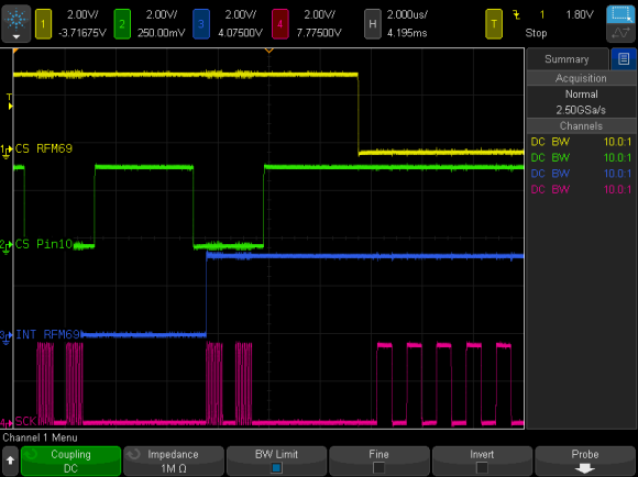
To prevent data corruption when using multiple SPI devices on the same bus, care must be taken to ensure that they are only accessed from within the main loop, or from the interrupt routine, never both. Data corruption can happen when one device is chip selected in the main loop, and then during that transfer an interrupt occurs, chip selecting another device. The original device now gets incorrect data.

For the last several weeks, [Paul] has been working on a new Arduino SPI library, to solve these types of conflicts. In the above scenario, the new library will generate a blocking SPI transaction, thus allowing the first main loop SPI transfer to complete, before attempting the second transfer. This is illustrated in the picture above, the blue trace rising edge is when the interrupt occurred, during the green trace chip select. The best part, it only affects SPI, your other interrupts will still happen on time. No servo jitter!

This is just one of the new library features, check out the link above for the rest. [Paul] sums it up best: “protects your SPI access from other interrupt-based libraries, and guarantees correct setting while you use the SPI bus”.


Filed under: Arduino Hacks


I'm lowering the top BTW


The engineering in the boat the cooling fan circulates air blowing it out between the motors. This wee fan moves lots of air on 7.4 Volts


Arduino Inputs from RX

Ch3   Throttle                       Arduino pin 4
Ch1   Steering                       Arduino pin 5
Ch5   Throttle limit                Arduino pin 6
Ch2   Steering on Throttle       Arduino pin 7

Arduino analogue inputs

Anin 0  Ambient temp sensor                      Anin 1  Hall effect current sensor

Arduino outputs

Pin 8    Left jet
Pin 9    Right jet
Pin 10  Cooling fan speed
Pin 11  Steering

Mixing of the outputs

    
  //SteeringBias
  
  int SterringOnThrottle = (long)map((int)ch4v, 1500, 1100, 0, 1000); 
  
  if(SterringOnThrottle < 0) SterringOnThrottle = 0;
  
  SteeringBias = (long)map((int)ch3v - (int)ch3vWOZ, 0, 1000, 0, SterringOnThrottle); 
    
  int SteeringAngle = (long)map((int)ch3v, 1100, 1900, 1000, 2000);
  
  //Limit fan speed for 11.1 V
  FanSpeed = map(FanSpeed, 1100, 1900, 1000, 1500);
  
  //Update the outputs
   
  Servo1.writeMicroseconds((int)Throttle - (int)SteeringBias);
  
  Servo2.writeMicroseconds((int)Throttle + (int)SteeringBias);
     
  Servo3.writeMicroseconds((int)FanSpeed);
   
  Servo4.writeMicroseconds((int)SteeringAngle);


The cooling system


The fan is a 27 mm EDF should keep the air moving with a 10A ESC


There is a big heatsink and fan on the 30 AMp ESC's


  • Newsletter

    Sign up for the PlanetArduino Newsletter, which delivers the most popular articles via e-mail to your inbox every week. Just fill in the information below and submit.

  • Like Us on Facebook