Posts | Comments

Planet Arduino

Archive for the ‘voltmeter’ Category

encoder1Watch a Redditor share how he hacked a DC motor and hooked it up to an Arduino to use as an encoder.

Read more on MAKE

The post Hack an Old DC Motor to Provide Rotary Input appeared first on Make: DIY Projects, How-Tos, Electronics, Crafts and Ideas for Makers.

May
03

Voltmeter using arduino

arduino, voltmeter Comments Off on Voltmeter using arduino 

voltmeter-using-arduinoby praveen:

This article is about a simple 3 digit voltmeter using arduino. The circuit can measure anything between 0 to 5V at an accuracy of 50mV. The circuit uses minimum number of external components and can be easily modified for different voltage ranges. The display device is a common anode multiplexed seven segment LED display module (Type No:E1-3056ASR1). Let’s have a look at the display device first.

Voltmeter using arduino - [Link]

Introduction

This is the second of three articles that will examine the LM391x series of LED driver ICs. The first covered the LM3914, this will cover the LM3915 and the LM3916 will follow. The goal of these is to have you using the parts in a small amount of time and experiment with your driver ICs, from which point you can research further into their theory and application.

Although these parts have been around for many years, the LM3915 isn’t used that much however for the sake of completeness we’re writing the tutorial. The LM3915 offers a simple way to display a logarithmic voltage level using one or more groups of ten LEDs with a minimum of fuss. If you’re wanting to make a VU meter, you should use the LM3916 which we will cover in the final instalment of this trilogy.

Instead of having each LED represent a voltage level as with the LM3914, each LED connected to the LM3915 represents a 3 dB (decibel) change in the power level of the signal. For more on decibels, check out Wikipedia.

To display these power level changes we’ll run through a couple of examples that you can use in your own projects and hopefully give you some ideas for the future. Originally by National Semiconductor, the LM391X series is now handled by Texas Instruments.

LM3915

Getting Started

You will need the LM3915 data sheet, so please download that and keep it as a reference. First – back to basics. The LM3915 controls ten LEDs. It controls the current through the LEDs with the use of only one resistor, and the LEDs can appear in a bar graph or single ‘dot’ when in use. The LM3915 contains a ten-stage voltage divider, each stage when reached will illuminate the matching LED (and those below it in level meter mode).

Let’s consider the most basic of examples (from page two of the data sheet) – a simple logarithmic display of voltage between 0 and 10V:

LM3915 demo board circuitAfter building the circuit you can connect a signal to measure via pin 5, and the GND to pin 2. We’ve built the circuit exactly as above on some stripboard for demonstration purposes, with the only difference being the use of an 8.2kΩ resistor for R2:

LM3915 demo board

To show this in action we use a signal of varying AC voltage – a sine wave at around 2 kHz. In the following video, you can see the comparison of the signal’s voltage against the LEDs being illuminated, and you will see the logarithmic voltage increase represented by the LEDs:

We used the bar display mode for the voltage increase, and the dot display mode for the voltage decrease. Did you notice that during the voltage decrease, the LEDs below the maximum level being displayed were dim? As the signal’s voltage was varying very quickly, the change in the LED’s location is a blur due to the speed of change. In the video below, we’ve slowed the frequency right down but kept the same maximum voltage.

Well that was a lot of fun, and gives you an idea of what is possible with the LM3915.

Displaying weaker signals

In non-theoretical situations your input signal won’t conveniently be between 0 and 10 V. For example the line level on audio equipment can vary between 1 and 3V peak to peak. For example, here’s a random DSO image from measuring the headphone output on my computer whilst playing some typical music:

audio signal LM3915 PC sound

Although it’s an AC signal we’ll treat it as DC for simplicity. So to display this random low DC voltage signal we’ll reduce the range of the display to 0~3V DC. This is done using  the same method as with the LM3914 – with maths and different resistors.

Consider the following formulae:

LM3915 reference voltage formula

As you can see the LED current (Iled) is simple, however we’ll need to solve for R1 and R2 with the first formula to get our required Vref of 3V. For our example circuit I use 2.2kΩ for R2 which gives a value of 1.8kΩ for R1. However putting those values in the ILED formula gives a pretty low current for the LEDs, about 8.3 mA. Live and learn – so spend time experimenting with values so you can match the required Vref and ILED.

Nevertheless in this video below we have the Vref of 3V and some music in from the computer as a sample source of low-voltage DC. This is not a VU meter! Wait for the LM3916 article to do that.

Again due to the rapid rate of change of the voltage, there is the blue between the maximum level at the time and 0V.

Chaining multiple LM3915s

This is covered well in the data sheet, so read it for more on using two LM3915s. Plus there are some great example circuits in the data sheet, for example the 100W audio power meter on page 26 and the vibration meter (using a piezo) on page 18.

Conclusion

As always I hope you found this useful. Don’t forget to stay tuned for the final instalment about the LM3916. And if you made it this far – check out my new book “Arduino Workshop” from No Starch Press.

In the meanwhile have fun and keep checking into tronixstuff.com. Why not follow things on twitterGoogle+, subscribe  for email updates or RSS using the links on the right-hand column? And join our friendly Google Group – dedicated to the projects and related items on this website. Sign up – it’s free, helpful to each other –  and we can all learn something.

Sep
13

Tutorial – LM3914 Dot/Bar Display Driver IC

bar, display, dot, driver, Electronics, example, IC, LED, level, LM3914, LM3915, LM3916, TI, tronixstuff, tutorial, voltmeter Comments Off on Tutorial – LM3914 Dot/Bar Display Driver IC 

Introduction

This is the first of three tutorials that will examine the LM391x series of LED driver ICs. In this first tutorial we cover the LM3914, then the LM3915 and LM3916 will follow. The goal of these tutorials is to have you using the parts in a small amount of time and experiment with your driver ICs, from which point you can research further into their theory and application.

Although these parts have been around for many years, the LM3914 in particular is still quite popular. It offers a simple way to display a linear voltage level using one or more groups of ten LEDs with a minimum of fuss.

With a variety of external parts or circuitry these LEDs can then represent all sorts of data, or just blink for your amusement. We’ll run through a few example circuits that you can use in your own projects and hopefully give you some ideas for the future. Originally by National Semiconductor, the LM391X series is now handled by Texas Instruments.

LM3914

Getting Started

You will need the LM3914 data sheet, so please download that and keep it as a reference. So – back to basics. The LM3914 controls ten LEDs. It controls the current through the LEDs with the use of only one resistor, and the LEDs can appear in a bar graph or single ‘dot’ when in use. The LM3914 contains a ten-stage voltage divider, each stage when reached will illuminate the matching LED (and those below it in level meter mode).

Let’s consider the most basic of examples (from page two of the data sheet) – a voltmeter with a range of 0~5V:

 LM3914 5V voltmeter circuit

The Vled rail is also connected to the supply voltage in our example. Pin 9 controls the bar/dot display mode – with it connected to pin 3 the LEDs will operate in bar graph mode, leave it open for dot mode. The 2.2uF capacitor is required only when “leads to the LED supply are 6″ or longer”. We’ve hooked up the circuit above, and created a 0~5V DC source via a 10kΩ potentiometer with a multimeter to show the voltage – in the following video you can see the results of this circuit in action, in both dot and bar graph mode:

Customising the upper range and LED current

Well that was exciting, however what if you want a different reference voltage? That is you want your display to have a range of 0~3 V DC? And how do you control the current flow through each LED? With maths and resistors. Consider the following formulae:

LM3914 formulae

As you can see the LED current (Iled) is simple, our example is 12.5/1210 which returned 10.3 mA – and in real life 12.7 mA (resistor tolerance is going to affect the value of the calculations).

Now to calculate a new Ref Out voltage – for example  we’ll shoot for a 3 V meter, and keep the same current for the LEDs. This requires solving for R2 in the equation above, which results with R2 = -R1 + 0.8R1V. Substituting the values – R2 = -1210 + 0.8 x 1210 x 3 gives a value of 1694Ω for R2. Not everyone will have the E48 resistor range, so try and get something as close as possible. We found a 1.8 kΩ for R2 and show the results in the following video:

You can of course have larger display range values, but a supply voltage of no more than 25 V will need to be equal to or greater than that value. E.g. if you want a 0~10 V display, the supply voltage must be >= 10V DC.

Creating custom ranges

Now we’ll look at how to create  a lower range limit, so you can have displays that (for example) can range from a non-zero positive value. For example, you want to display levels between 3 and 5V DC. From the previous section, you know how to set the upper limit, and setting the lower limit is simple – just apply the lower voltage to pin 4 (Rlo).

You can derive this using a resistor divider or other form of supply with a common GND. When creating such circuits, remember that the tolerance of the resistors used in the voltage dividers will have an affect on the accuracy. Some may wish to fit trimpots, which after alignment can be set permanently with a blob of glue.

Finally, for more reading on this topic – download and review the TI application note.

Chaining multiple LM3914s

Two or more LM3914s can be chained together to increase the number of LEDs used to display the levels over an expanded range. The circuitry is similar to using two independent units, except the REFout (pin 7) from the first LM3914 is fed to the REFlo (pin 4) of the second LM3914 – whose REFout is set as required for the upper range limit. Consider the following example schematic which gave a real-world range of 0~3.8V DC:

LM3914

The 20~22kΩ resistor is required if you’re using dot mode (see “Dot mode carry” in page ten of the data sheet). Moving on, the circuit above results with the following:

Where to from here?

Now you can visually represent all sorts of low voltages for many purposes. There’s more example circuits and notes in the LM3914 data sheet, so have a read through and delve deeper into the operation of the LM3914. Furthermore Dave Jones from eevblog.com has made a great video whcih describes a practical application of the LM3914:

Conclusion

As always I hope you found this useful. Don’t forget to stay tuned for the second and third instalments using the LM3915 and LM3916. Full-sized images are on flickr. And if you made it this far – check out my new book “Arduino Workshop” from No Starch Press.

In the meanwhile have fun and keep checking into tronixstuff.com. Why not follow things on twitterGoogle+, subscribe  for email updates or RSS using the links on the right-hand column? And join our friendly Google Group – dedicated to the projects and related items on this website. Sign up – it’s free, helpful to each other –  and we can all learn something.

The post Tutorial – LM3914 Dot/Bar Display Driver IC appeared first on tronixstuff.

Hello everyone!

Today we are going to introduce the basics of AC – alternating current. This is necessary in order to understand future articles, and also to explain in layperson’s terms what AC is all about. So let’s go!

AC – Alternating Current. We see those two letters all around us. But what is alternating current? How does current alternate? We know that DC (direct current) is the result of a chemical reaction of some sort – for example in a battery, or from a solar cell. We know that it can travel in either direction, and we have made use of it in our experimenting. DC voltage does not alter (unless we want it to).

Therein lies the basic difference – and why alternating current is what is is – it alternates! :) This is due to the way AC current is created, usually by a generator of some sort. In simple terms a generator can be thought of as containing a rotating coil of wire between two magnets. When a coil passes a magnet, a current is induced by the magnetic field. So when the coil rotates, a current is induced, and the resulting voltage is relative to the coil’s positioning with the magnets.

For example, consider the diagram below (exploded view, it is normally more compact):

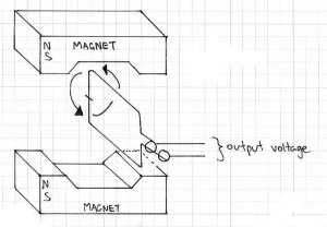
This is a very basic generator. A rotating coil of wire is between two magnets. The spacing of the magnets in real life is much closer. So as the coil rotates, the magnetic fields induce a current through the coil, which is our alternating current. But as the coil rotates around and around, the level of voltage is relative to the distance between the coil and the magnet. The voltage increases from zero, then decreases, then increases… as the coil constantly rotates. If you were to graph the voltage level (y-axis) against time (x-axis), it would look something like below:

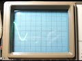
That graph is a sine wave… and is a representation of perfect AC current. If you were to graph DC voltage against time, it would be a straight horizontal line. For example, compare the two images below, 2 volts DC and AC, shown on an oscilloscope:

2 volts DC

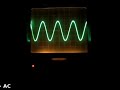
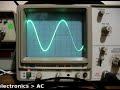
The following clip is 2 volts AC, as shown on the oscilloscope:

So as you can see, AC is not a negative and positive current like DC, it swings between negative and positive very quickly. So how do you take the voltage measurement? Consider the following:

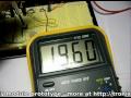
The zero-axis is the point of reference with regards to voltage. That is, it is the point of zero volts. In the oscilloscope video above, the maximum and minimum was 2 volts. Therefore we would say it was 2 volts peak, or 2Vp. It could also be referred to as 4 volts peak to peak, or 4Vpp – as there is a four volt spread between the maximum and minimum values of the sine wave. There is another measurement in the diagram above – Vrms, or volts root mean squared. The Vrms value is the amount of AC that can do the same amount of work as the equivalent DC voltage. Vrms = 0.707 x Vp; and Vp = 1.41 * Vrms. Voltages of power outlets are rated at Vrms instead of peak as this is relative to calculations. For example, in Australia we have 240 volts:

DO NOT do this

Well, close enough. In fact, our electricity distributor says we can have a tolerance of +/- 10%… some rural households can have around 260 volts. Moving on…

The final parameter of AC is the frequency, or how many times per second the voltage changes from zero to each peak then back to zero. That is the time for one complete cycle. The number of times this happens per second is the frequency, and is measured in Hertz (Hz). The most common frequency you will hear about is your domestic supply frequency. Australia is 50 Hz, the US is 60 Hz, etc. In areas that have a frequency of 60 Hz, accurate mains-powered time pieces can be used, as the seconds hand or counter can be driven from the frequency of the AC current.

The higher the frequency, the shorter the period of time taken by one cycle. The frequency and time are inversely proportional, so frequency = 1/time; and time – 1/frequency. For example, if your domestic supply is 50 Hz, the time for each cycle is 1/50 = 0.02 seconds. This change can be demonstrated quite well on an oscilloscope, for example:

In the video above there is 2 volts AC, and the frequency starts from 100 Hz, then moves around the range of 10 to 200 Hz. As you can see, the amplitude of the sine wave does not change (the height, which indicates the voltage) but the time period does alter, indicating the frequency is changing. And here is the opposite:

This video is a demonstration of changing the voltage, whilst maintaining a fixed frequency.

Thus ends the introduction to alternating current. In the next instalment about AC we will look at how AC works in electronic circuits, and how it is handled by various components.

I hope you understood and can apply what we have discussed today. As always, thank you for reading and I look forward to your comments and so on. Furthermore, don’t be shy in pointing out errors or places that could use improvement.

Please subscribe using one of the methods at the top-right of this web page to receive updates on new posts. Or join our Google Group and post your questions there.

Otherwise, have fun, be good to each other – and make something! :)


May
02

Greeting again to followers of the bbboost journey. It has been a month since the last instalment, however the 20V DC plug pack took a long time to arrive from the land of China. Nevertheless, the project is moving forward. For my new readers, the bbboost is a power supply that can be assembled by a beginner, and can offer a smooth variable DC output voltage of between ~1.8 and ~20 volts – perfect for experimenting, breadboard, and generally saving money by not buying batteries. You can just make a PCB version, or mount it in an enclosure like a professional desktop unit. No mains voltage wiring is required, so it will fine for the younger enthusiasts. Follow the project from here.

This time I have breadboarded the power supply module, using the circuit described in chapter two.  Let’s have a bit of a look:

These trimpots were ok, but it would be preferable to use the fully enclosed dustproof versions. Will order some and try ‘em out.

One trimpot (the blue and white one) is 5k ohm, – to adjust between the full range, so this is the ‘coarse’ adjuster; the other trimpot is only 500 ohms and changes the voltage selected by the coarse pot by around +/- 1.2 volts. The purpose of having two controls is to make it very easy to select your required voltage down to one-hundredth of a volt. The following video clip is a rough example of this type of adjustment in action:

This power supply will also be designed for installation into a nice enclosure, so in that case one would use normal-sized potentiometers for the coarse and fine voltage adjustment. Will try that for the next instalment.

So,  thank you once more for reading. Please leave feedback and constructive criticism or comments at your leisure… and to keep track, subscribe using the services at the top right of this page!


  • Newsletter

    Sign up for the PlanetArduino Newsletter, which delivers the most popular articles via e-mail to your inbox every week. Just fill in the information below and submit.

  • Like Us on Facebook