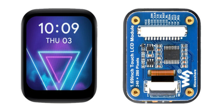
The Waveshare 1.69-inch IPS touch LCD is a 1.69-inch rounded display with 240×280 resolution and a 262K color range. The display driver (ST7789V2) and touch controller (CST816T) are integrated on-board and rely on SPI and I2C interfaces that make it compatible with popular platforms such as Raspberry Pi, Arduino, ESP32, STM32, and more. Previously we have covered many similar display modules like the MaTouch ESP32-S3, T-RGB ESP32-S3, and ESP32-S3 Round SPI TFT. Feel free to check these out if you are looking for a specific rounded display product. Waveshare 1.69-inch IPS touch LCD specifications Display 1.69-inch round LCD with 240×280 resolution and IPS panel. 262K color depth Display Driver – ST7789V2 SPI display driver Touch Control – CST816T I2C capacitive touch controller for responsive input. Onboard Logic Level Converter – Onboard voltage translator for 3.3V/5V power, works with Raspberry Pi, ESP32-S3, Raspberry Pi Pico, Arduino, STM32, and more. Dimensions – 41.13 x 33.13 [...]
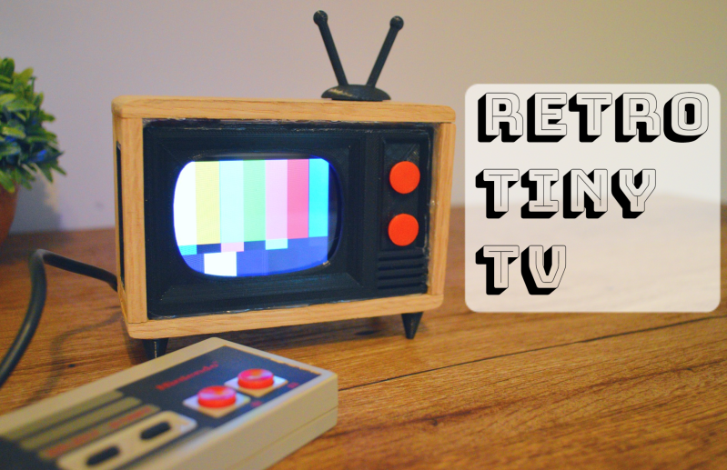
Once upon a time, we would run home from the bus stop to watch Gargoyles and Brady Bunch reruns on the family TV, a late-1970s console Magnavox number that sat on the floor and was about 50% more cabinet than CRT. The old TV, a streamlined white Zenith at least ten years older, had been relegated to the man cave in the basement. It looked so mod compared to the “new” TV, but that’s not the aesthetic my folks were after. They wanted their electronics to double as furniture.
This little TV is a happy medium between the two styles, and for us, it’s all about those feet. But instead of cartoons, it switches between showing the current weather and the top news headlines. Inside that classy oak cabinet is an LCD, an ESP32, and an SD card module. The TV uses OpenWeatherMap and pulls the corresponding weather image from the SD card based on time of day — light images for day, and dark images for night.
We love that it shows the SMPTE color bars, aka the standard American TV test pattern as it switches between weather and news. After showing the top headlines, it automatically switches back to the weather channel. Be sure to check out the short demo video after the break.
A while back, [Kutluhan Aktar] was trying to hack their chickens, quails, and ducks for higher egg production and faster hatching times by using a bit of classical conditioning. That is, feeding them at the same time every day while simultaneously exposing them to sound and light. Once [Kutluhan] slipped enough times, they hatched a plan to build an automatic feeder.
This fun rooster-shaped bird feeder runs on an Arduino Nano and gets its time, date, and temperature info from a DS3231 RTC. All [Kutluhan] has to do is set the daily feeding time. When it comes, a pair of servos and a pan-tilt kit work together to invert a Pringles can filled with food pellets. A piezo buzzer and a green LED provide the sound and light to help with conditioning. Scratch your way past the break to see it in action.
Feature creep is typically something to be avoided, since watching a relatively simple project balloon into a rat’s nest of complexity often leads to ineffective, or even abandoned, projects. On the other hand, if you can maintain a tight focus, it’s not always a bad thing. [cbm80Amiga] shows us how to drill down and add specific features in this single-button timer without losing focus on what the original project was all about.
The timer is based on an Arduino Pro Mini and an HX1230 LCD with a simple piezo speaker for audible alerts. A single button controls operation of the timer, with short presses incrementing each digit and long presses moving on to the next digit. Controlling button presses this finely is a project in its own, but then [cbm80Amiga] moves on to other features such as backlight control, low power modes which allow it to operate for around two years on a single battery charge, preset times for various kitchen uses, and different appearance settings.
Honestly we aren’t sure how you could cram any more features on this timer without fundamentally altering the designed simplicity. It doesn’t fall into the abyss of feature creep while being packed with features, and it’s another example of how keeping things simple is often a recipe for success.
Bowling has been around since ancient Egypt and continues to entertain people of all ages, especially once they roll out the fog machine and hit the blacklights. But why pay all that money to don used shoes and drink watered-down beer? Just build a tabletop bowling alley in your spare time and you can bowl barefoot if you want.
Those glowing pins aren’t just for looks — the LEDs underneath them are part of the scoring system. Whenever a pin is knocked out of its countersunk hole, the LED underneath is exposed and shines its light on a corresponding light-dependent resistor positioned overhead. An Arduino Uno keeps track of of the frame, ball number, and score, and displays it on an LCD.
The lane is nearly six feet long, so this is more like medium-format bowling or maybe even skee-bowling. There are probably a number of things one could use for balls, but [lainealison] is using large ball bearings. Roll past the break to see it in action, but don’t go over the line!
The purpose of this guide is to get your 0.96″ color LCD display successfully operating with your Arduino, so you can move forward and experiment and explore further types of operation with the display. This includes installing the Arduino library, making a succesful board connection and running a demonstration sketch.
Although you can use the display with an Arduino Uno or other boad with an ATmega328-series microcontroller – this isn’t recommended for especially large projects. The library eats up a fair amount of flash memory – around 60% in most cases.
So if you’re running larger projects we recommend using an Arduino Mega or Due-compatible board due to the increased amount of flash memory in their host microcontrollers.
Installing the Arduino library
So let’s get started. We’ll first install the Arduino library then move on to hardware connection and then operating the display.
(As the display uses the ST7735S controller IC, you may be tempted to use the default TFT library included with the Arduino IDE – however it isn’t that reliable. Instead, please follow the instructions below).
First – download the special Arduino library for your display and save it into your Downloads or a temp folder.
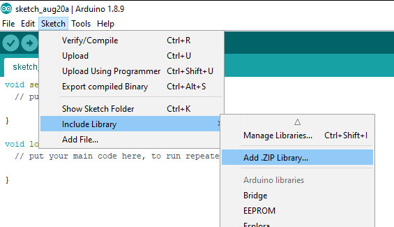
Next – open the Arduino IDE and select the Sketch > Include Library > Add .ZIP library option as shown below:
A dialog box will open – navigate to and select the zip file you downloaded earlier. After a moment or two the IDE will then install the library.
Please check that the library has been installed – to do this, select the Sketch > Include Library option in the IDE and scroll down the long menu until you see “ER-TFTM0.96-1” as shown below:
Once that has been successful, you can wire up your display.
Connecting the display to your Arduino
The display uses the SPI data bus for communication, and is a 3.3V board. You can use it with an Arduino or other 5V board as the logic is tolerant of higher voltages.
Arduino to Display
GND ----- GND (GND)

3.3V ---- Vcc (3.3V power supply)

D13 ----- SCL (SPI bus clock)

D11 ----- SDA (SPI bus data out from Arduino)

D10 ----- CS (SPI bus "Chip Select")

D9 ------ DC (Data instruction select pin)

D8 ------ RES (reset input)
If your Arduino has different pinouts than the Uno, locate the SPI pins for your board and modify as appropriate.
Demonstration sketch
Open a new sketch in the IDE, then copy and paste the following sketch into the IDE:
// https://pmdway.com/products/0-96-80-x-160-full-color-lcd-module#include<UTFT.h>// Declare which fonts we will be usingexternuint8_tSmallFont[];// Initialize display// Library only supports software SPI at this time//NOTE: support DUE , MEGA , UNO //SDI=11 SCL=13 /CS =10 /RST=8 D/C=9UTFTmyGLCD(ST7735S_4L_80160,11,13,10,8,9);//LCD: 4Line serial interface SDI SCL /CS /RST D/C NOTE:Only support DUE MEGA UNO// Declare which fonts we will be usingexternuint8_tBigFont[];intcolor=0;wordcolorlist[]={VGA_WHITE,VGA_BLACK,VGA_RED,VGA_BLUE,VGA_GREEN,VGA_FUCHSIA,VGA_YELLOW,VGA_AQUA};intbsize=4;voiddrawColorMarkerAndBrushSize(intcol){myGLCD.setColor(VGA_BLACK);myGLCD.fillRect(25,0,31,239);myGLCD.fillRect(myGLCD.getDisplayXSize()-31,161,myGLCD.getDisplayXSize()-1,191);myGLCD.setColor(VGA_WHITE);myGLCD.drawPixel(25,(col*30)+15);for(inti=1;i<7;i++)myGLCD.drawLine(25+i,((col*30)+15)-i,25+i,((col*30)+15)+i);if(color==1)myGLCD.setColor(VGA_WHITE);elsemyGLCD.setColor(colorlist[col]);if(bsize==1)myGLCD.drawPixel(myGLCD.getDisplayXSize()-15,177);elsemyGLCD.fillCircle(myGLCD.getDisplayXSize()-15,177,bsize);myGLCD.setColor(colorlist[col]);}voidsetup(){randomSeed(analogRead(0));// Setup the LCDmyGLCD.InitLCD();myGLCD.setFont(SmallFont);}voidloop(){intbuf[158];intx,x2;inty,y2;intr;// Clear the screen and draw the framemyGLCD.clrScr();myGLCD.setColor(255,0,0);myGLCD.fillRect(0,0,159,13);myGLCD.setColor(64,64,64);myGLCD.fillRect(0,114,159,127);myGLCD.setColor(255,255,255);myGLCD.setBackColor(255,0,0);myGLCD.print("pmdway.com.",CENTER,1);myGLCD.setBackColor(64,64,64);myGLCD.setColor(255,255,0);myGLCD.print("pmdway.com",LEFT,114);myGLCD.setColor(0,0,255);myGLCD.drawRect(0,13,159,113);// Draw crosshairsmyGLCD.setColor(0,0,255);myGLCD.setBackColor(0,0,0);myGLCD.drawLine(79,14,79,113);myGLCD.drawLine(1,63,158,63);myGLCD.setColor(0,0,255);myGLCD.drawLine(0,79,159,79);for(inti=9;i<150;i+=10)myGLCD.drawLine(i,61,i,65);for(inti=19;i<110;i+=10)myGLCD.drawLine(77,i,81,i);// Draw sin-, cos- and tan-lines myGLCD.setColor(0,255,255);myGLCD.print("Sin",5,15);for(inti=1;i<158;i++){myGLCD.drawPixel(i,63+(sin(((i*2.27)*3.14)/180)*40));}myGLCD.setColor(255,0,0);myGLCD.print("Cos",5,27);for(inti=1;i<158;i++){myGLCD.drawPixel(i,63+(cos(((i*2.27)*3.14)/180)*40));}myGLCD.setColor(255,255,0);myGLCD.print("Tan",5,39);for(inti=1;i<158;i++){myGLCD.drawPixel(i,63+(tan(((i*2.27)*3.14)/180)));}delay(2000);myGLCD.setColor(0,0,0);myGLCD.fillRect(1,14,158,113);myGLCD.setColor(0,0,255);myGLCD.setBackColor(0,0,0);myGLCD.drawLine(79,14,79,113);myGLCD.drawLine(1,63,158,63);myGLCD.setColor(0,0,255);myGLCD.drawLine(0,79,159,79);// Draw a moving sinewavex=1;for(inti=1;i<(158*20);i++){x++;if(x==159)x=1;if(i>159){if((x==79)||(buf[x-1]==63))myGLCD.setColor(0,0,255);elsemyGLCD.setColor(0,0,0);myGLCD.drawPixel(x,buf[x-1]);}myGLCD.setColor(0,255,255);y=63+(sin(((i*2.5)*3.14)/180)*(40-(i/100)));myGLCD.drawPixel(x,y);buf[x-1]=y;}delay(2000);myGLCD.setColor(0,0,0);myGLCD.fillRect(1,14,158,113);myGLCD.setColor(0,0,255);myGLCD.drawLine(0,79,159,79);// Draw some filled rectanglesfor(inti=1;i<6;i++){switch(i){case1:myGLCD.setColor(255,0,255);break;case2:myGLCD.setColor(255,0,0);break;case3:myGLCD.setColor(0,255,0);break;case4:myGLCD.setColor(0,0,255);break;case5:myGLCD.setColor(255,255,0);break;}myGLCD.fillRect(39+(i*10),23+(i*10),59+(i*10),43+(i*10));}delay(2000);myGLCD.setColor(0,0,0);myGLCD.fillRect(1,14,158,113);myGLCD.setColor(0,0,255);myGLCD.drawLine(0,79,159,79);// Draw some filled, rounded rectanglesfor(inti=1;i<6;i++){switch(i){case1:myGLCD.setColor(255,0,255);break;case2:myGLCD.setColor(255,0,0);break;case3:myGLCD.setColor(0,255,0);break;case4:myGLCD.setColor(0,0,255);break;case5:myGLCD.setColor(255,255,0);break;}myGLCD.fillRoundRect(99-(i*10),23+(i*10),119-(i*10),43+(i*10));}delay(2000);myGLCD.setColor(0,0,0);myGLCD.fillRect(1,14,158,113);myGLCD.setColor(0,0,255);myGLCD.drawLine(0,79,159,79);// Draw some filled circlesfor(inti=1;i<6;i++){switch(i){case1:myGLCD.setColor(255,0,255);break;case2:myGLCD.setColor(255,0,0);break;case3:myGLCD.setColor(0,255,0);break;case4:myGLCD.setColor(0,0,255);break;case5:myGLCD.setColor(255,255,0);break;}myGLCD.fillCircle(49+(i*10),33+(i*10),15);}delay(2000);myGLCD.setColor(0,0,0);myGLCD.fillRect(1,14,158,113);myGLCD.setColor(0,0,255);myGLCD.drawLine(0,79,159,79);// Draw some lines in a patternmyGLCD.setColor(255,0,0);for(inti=14;i<113;i+=5){myGLCD.drawLine(1,i,(i*1.44)-10,112);}myGLCD.setColor(255,0,0);for(inti=112;i>15;i-=5){myGLCD.drawLine(158,i,(i*1.44)-12,14);}myGLCD.setColor(0,255,255);for(inti=112;i>15;i-=5){myGLCD.drawLine(1,i,172-(i*1.44),14);}myGLCD.setColor(0,255,255);for(inti=15;i<112;i+=5){myGLCD.drawLine(158,i,171-(i*1.44),112);}delay(2000);myGLCD.setColor(0,0,0);myGLCD.fillRect(1,14,158,113);myGLCD.setColor(0,0,255);myGLCD.drawLine(0,79,159,79);// Draw some random circlesfor(inti=0;i<100;i++){myGLCD.setColor(random(255),random(255),random(255));x=22+random(116);y=35+random(57);r=random(20);myGLCD.drawCircle(x,y,r);}delay(2000);myGLCD.setColor(0,0,0);myGLCD.fillRect(1,14,158,113);myGLCD.setColor(0,0,255);myGLCD.drawLine(0,79,159,79);// Draw some random rectanglesfor(inti=0;i<100;i++){myGLCD.setColor(random(255),random(255),random(255));x=2+random(156);y=16+random(95);x2=2+random(156);y2=16+random(95);myGLCD.drawRect(x,y,x2,y2);}delay(2000);myGLCD.setColor(0,0,0);myGLCD.fillRect(1,14,158,113);myGLCD.setColor(0,0,255);myGLCD.drawLine(0,79,159,79);// Draw some random rounded rectanglesfor(inti=0;i<100;i++){myGLCD.setColor(random(255),random(255),random(255));x=2+random(156);y=16+random(95);x2=2+random(156);y2=16+random(95);myGLCD.drawRoundRect(x,y,x2,y2);}delay(2000);myGLCD.setColor(0,0,0);myGLCD.fillRect(1,14,158,113);myGLCD.setColor(0,0,255);myGLCD.drawLine(0,79,159,79);for(inti=0;i<100;i++){myGLCD.setColor(random(255),random(255),random(255));x=2+random(156);y=16+random(95);x2=2+random(156);y2=16+random(95);myGLCD.drawLine(x,y,x2,y2);}delay(2000);myGLCD.setColor(0,0,0);myGLCD.fillRect(1,14,158,113);myGLCD.setColor(0,0,255);myGLCD.drawLine(0,79,159,79);for(inti=0;i<5000;i++){myGLCD.setColor(random(255),random(255),random(255));myGLCD.drawPixel(2+random(156),16+random(95));}delay(2000);myGLCD.fillScr(0,0,255);myGLCD.setColor(255,0,0);myGLCD.fillRoundRect(10,17,149,72);myGLCD.setColor(255,255,255);myGLCD.setBackColor(255,0,0);myGLCD.print("That's it!",CENTER,20);myGLCD.print("Restarting in a",CENTER,45);myGLCD.print("few seconds...",CENTER,57);myGLCD.setColor(0,255,0);myGLCD.setBackColor(0,0,255);myGLCD.print("Runtime: (msecs)",CENTER,103);myGLCD.printNumI(millis(),CENTER,115);delay(5000);}
Once you’re confident with the physical connection, upload the sketch. It should result with output as shown in the video below:
Now that you have succesfully run the demonstration sketch – where to from here?
The library used is based on the uTFT library by Henning Karlsen. You can find all the drawing and other commands in the user manual – so download the pdf and enjoy creating interesting displays.
This post brought to you by pmdway.com – everything for makers and electronics enthusiasts, with free delivery worldwide.
To keep up to date with new posts at tronixstuff.com, please subscribe to the mailing list in the box on the right, or follow us on twitter @tronixstuff.
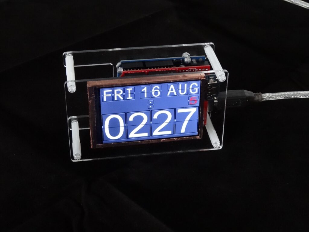
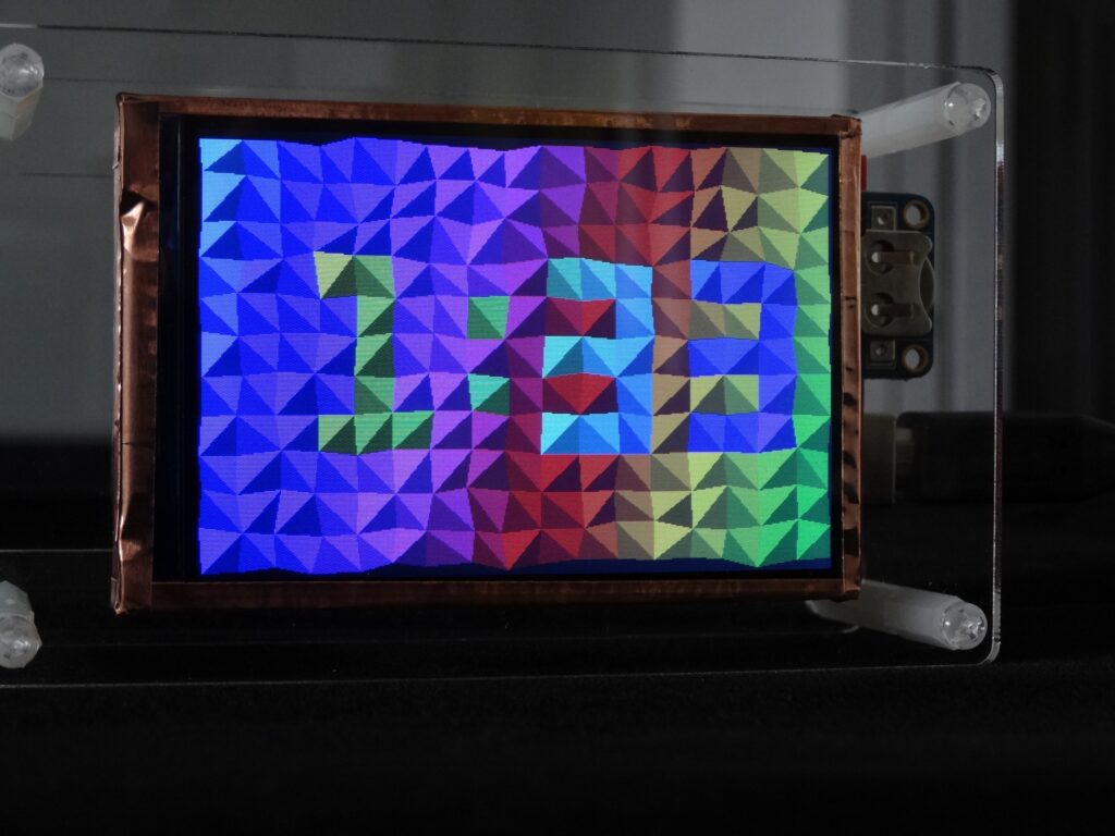
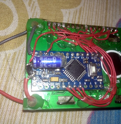
Although flip clocks may be extremely interesting electromechanical devices, with rolling flaps to show what time it is, they’re also fairly complicated if you want to build one yourself. Mark Wilson, however, took a different approach with his project, simulating the output on a 320×240 LCD display.
The clock is powered by an Arduino Uno and a DS3231 RTC module, allowing it to show the time, date, a blinking colon, and even the days until the trash/recycling needs to be put out. Alternate screens are available as well, including a Pong clock, triangle clock, and cube clock, which can be individually selected or set to randomly cycle if you so desire.
For its housing, Wilson chose a minimal acrylic/standoff design that seems to suit it well, and you can see it in action in the short demo clip below.
The basic 16×2 LCD is an extremely popular component that we’ve seen used in more projects than we could possibly count. Part of that is because modern microcontrollers make it so easy to work with; if you’ve got an I2C variant of the display, it only takes four wires to drive it. That puts printing a line of text on one of these LCDs a step or two above blinking an LED on a digital pin on the hierarchy of beginner’s electronics projects.
What’s that? Even four wires is too many? In that case, you might be interested in this hack from [Vinod] which shows how you can drive the classic 16×2 with data and power on the same pair of wires. You’ll still need a microcontroller “backpack” for the LCD to interpret the modulated voltage, but if you’ve got an application for a simple remote display, this is definitely worth checking out.
The basic idea is to “blink” the 5 V line so quick that a capacitor on the LCD side can float the electronics over the dips in voltage. As long as one of the pins of the microcontroller is connected to the 5 V line before the capacitor, it will be able to pick up when the line goes low. With a high enough data rate and a large enough capacitor as a buffer, you’re well on the way to encoding your data to be displayed.
For the transmitting side, [Vinod] is using a Python script on his computer that’s sending out the text for the LCD over a standard USB to UART converter. That’s fed into a small circuit put together on a scrap of perfboard that triggers a MOSFET off of the UART TX line.
These days, you could be forgiven for thinking driving an LCD from a microcontroller is easy. Cheap displays have proliferated, ready to go on breakout boards with controllers already baked in. Load up the right libraries and you’re up and running in a matter of minutes. However, turn your attention to trying to drive a random LCD you’ve yanked out of a piece of old equipment, and suddenly things get harder. [Ivan Kostoski] was in just such a position and decided to get down to work.
[Ivan]’s LCD was a 320×240 STN device salvaged from an old tape library. The display featured no onboard controller, and the original driver wasn’t easily repurposed. Instead, [Ivan] decided to drive it directly from an Arduino Uno.
This is easier said than done. There are stringent timing requirements that push the limits of the 8-bit platform, let alone the need for a negative voltage to drive the screen and further hardware to drive the backlight. These are all tackled in turn, with [Ivan] sharing his tips to get the most flexibility out of the display. Graphics and text modes are discussed, along with optimizations that could be possible through the varied use of available RAM and flash.
There are plenty of cheap projection clocks available, but as [Thomas Pototschnig] points out in this project, where’s the fun in just buying something? He set out to build a cheap projection clock using a small LCD screen, a cheap LED backlight, and a cheap lens. Cheap is the order of the day here, and [Thomas] succeeded admirably, creating a design that can be made with a couple of cheap PCBs, a 3D printer and the other parts mentioned above. He does a nice job of laying out his thinking in this design, showing how he calculated the projection path and made other decisions. His project has room to grow as well: it runs from an Arduino compatible STM32 that could handle many things other than showing the time if you were inclined to expand the project further.
[Thomas] has released all of the files he created for the project, including a number of options for the case that can use C-mount and Sony E-mount lenses. I’m not sure if you would want to attach your expensive camera lenses to a home-made projector like this, but it’s good to have the option if you have a dead E-mount lens that you were going to tear apart for parts anyway.
Planet Arduino is, or at the moment is wishing to become, an aggregation of public weblogs from around the world written by people who develop, play, think on Arduino platform and his son. The opinions expressed in those weblogs and hence this aggregation are those of the original authors. Entries on this page are owned by their authors. We do not edit, endorse or vouch for the contents of individual posts. For more information about Arduino please visit www.arduino.cc
You are currently browsing the archives for the LCD category.