07
mbed and the Freescale FRDM-KL25Z development board
Accelerometer, ARM, arm cortex, capacitive, cortex, education, element14, FRDM-KL25Z, freedom, freescale, i2c, KL25Z, M0+, mbed, MKL25Z128VLK4, MMA8451Q, opensda, part review, review, Sensor, Touch, tronixstuff, tutorial Comments Off on mbed and the Freescale FRDM-KL25Z development board
In this article we examine the mbed rapid prototyping platform with the Freescale FRDM-KL25Z ARM® Cortex™-M0+ development board.
Introduction
A while ago we looked at the mbed rapid prototyping environment for microcontrollers with the cloud-based IDE and the NXP LPC1768 development board, and to be honest we left it at that as I wasn’t a fan of cloud-based IDEs. Nevertheless, over the last two or so years the mbed platform has grown and developed well – however without too much news on the hardware side of things. Which was a pity as the matching development boards usually retailed for around $50 … and most likely half the reason why mbed didn’t become as popular as other rapid development platforms.
Also – a few months ago – we received the new Freescale Freedom FRDM-KL25Z development board from element14. I started to write about using the board but frankly it did my head in, as at the time the IDE was almost a one gigabyte download and the learning curve too steep for the time I had available. Which was a pity as the board is inexpensive and quite powerful. So the board went into the “miscellaneous dev kit” box graveyard. Until now. Why?
You can now use the Freedom board with mbed.
It isn’t perfect – yet – but it’s a move in the right direction for both mbed and Freescale. It allows educators and interested persons access to a very user-friendly IDE and dirt-cheap development boards.
What is mbed anyway?
mbed is a completely online development environment. That is, in a manner very similar to cloud computing services such as Google Docs or Zoho Office. However there are some pros and cons of this method. The pros include not having to install any software on the PC – as long as you have a web browser and a USB port you should be fine; any new libraries or IDE updates are handled on the server leaving you to not worry about staying up to date; and the online environment can monitor and update your MCU firmware if necessary. However the cons are that you cannot work with your code off-line, and there may be some possible privacy issues. Here’s an example of the environment (click to enlarge):
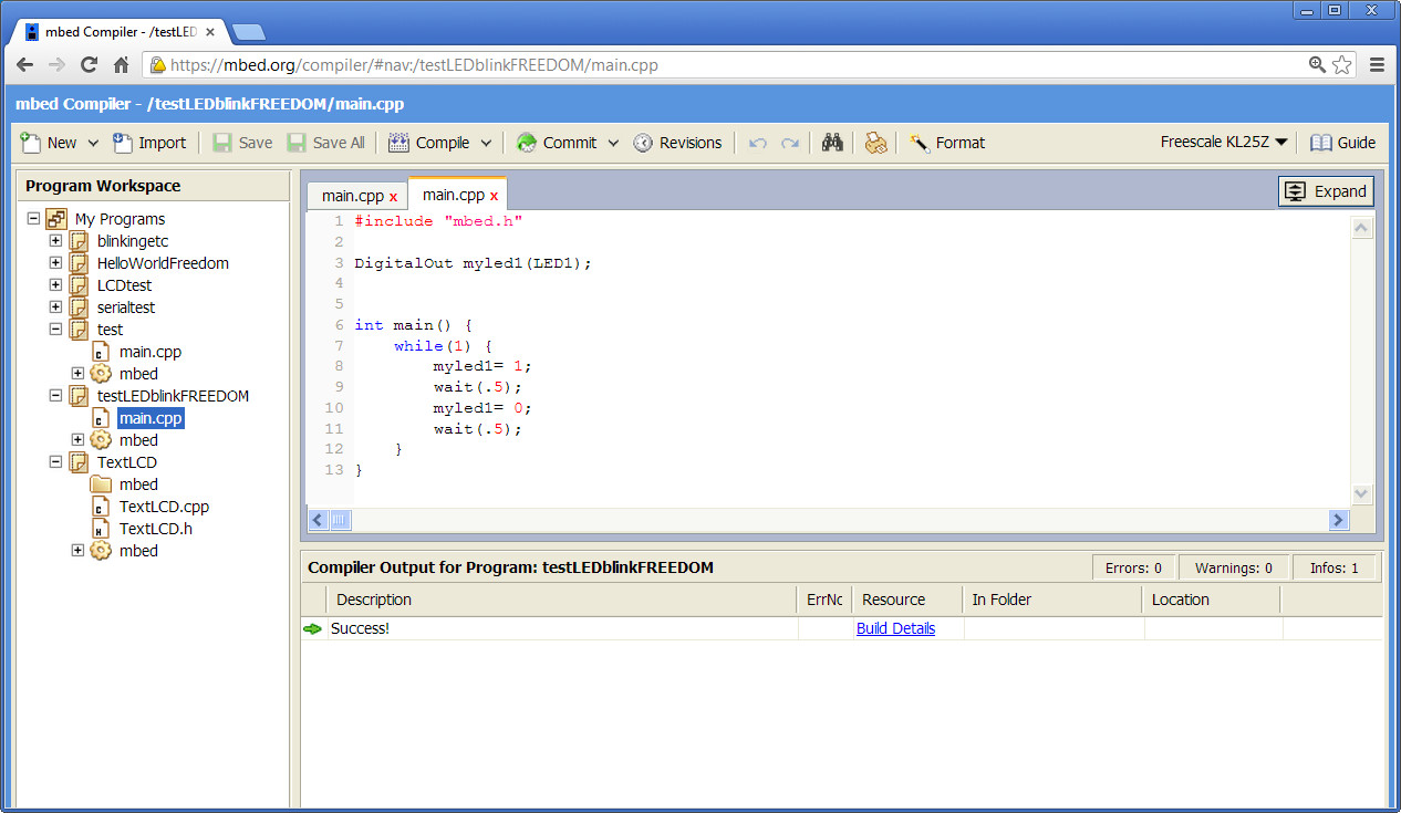
As you can see the IDE is quite straight-forward. All your projects can be found on the left column, the editor in the main window and compiler and other messages in the bottom window. There’s also an online support forum, an official mbed library and user-submitted library database, help files and so on – so there’s plenty of support. Code is written in C/C++ style and doesn’t present any major hurdles. When it comes time to run the code, the online compiler creates a downloadable binary file which is copied over to the hardware via USB.
And what’s a Freedom board?
It’s a very inexpensive development board based on the Freescale ARM® Cortex™-M0+ MKL25Z128VLK4 microcontroller. How inexpensive? In Australia it’s $9 plus GST and delivery.
Features include (from the product website):
- MKL25Z128VLK4 MCU – 48 MHz, 128 KB flash, 16 KB SRAM, USB OTG (FS), 80LQFP
- Capacitive touch “slider,” MMA8451Q accelerometer, tri-color LED
- Easy access to MCU I/O
- Sophisticated OpenSDA debug interface
- Mass storage device flash programming interface (default) – no tool installation required to evaluate demo apps
- P&E Multilink interface provides run-control debugging and compatibility with IDE tools
- Open-source data logging application provides an example for customer, partner and enthusiast development on the OpenSDA circuit
And here it is:

In a lot of literature about the board it’s mentioned as being “Arduino compatible”. This is due to the layout of the GPIO pins – so if you have a 3.3 V-compatible Arduino shield you may be able to use it – but note that the I/O pins can only sink or source 3 mA (from what I can tell) – so be careful with the GPIO . However on a positive side the board has the accelerometer and an RGB LED which are handy for various uses. Note that the board ships without any stacking header sockets, but element14 have a starter pack with those and a USB cable for $16.38++.
Getting started
Now we”ll run through the process of getting a Freedom board working with mbed and creating a first program. You’ll need a computer (any OS) with USB, an Internet connection and a web browser, a USB cable (mini-A to A) and a Freedom board. The procedure is simple:
- Download and install the USB drivers for Windows or Linux from here.
- Visit mbed.org and create a user account. Check your email for the confirmation link and follow the instructions within.
- Plug in your Freedom board – using the USB socket labelled “OpenSDA”. It will appear as a disk called “bootloader”
- Download this file and copy it onto the “bootloader” drive
- Unplug the Freedom board, wait a moment – then plug it back in. It should now appear as a disk called “MBED”, for example (click to enlarge):
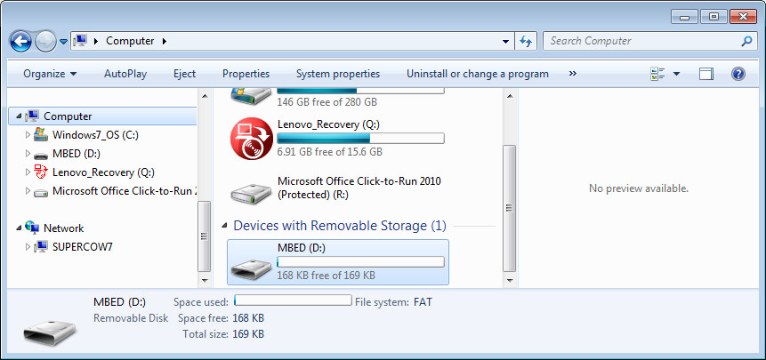
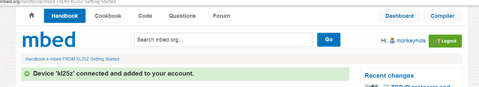
There will be a file called ‘mbed’ on the mbed drive – double-click this to open it in a web browser. This process activates the board on your mbed account – as shown below (click to enlarge):
Now you’re ready to write your code and upload it to the Freedom board. Click “Compiler” at the top-right to enter the IDE.
Creating and uploading code
Now to create a simple program to check all is well. When you entered the IDE in the previous step, it should have presented you with the “Guide to mbed Online Compiler”. Have a read, then click “New” at the top left. Give your program a name and click OK. You will then be presented with a basic “hello world” program that blinks the blue LED in the RGB module. Adjust the delays to your liking then click “Compile” in the toolbar.
If all is well, your web browser will present you with a .bin file that has been downloaded to the default download directory. (If not, see the error messages in the area below the editor pane). Now copy this .bin file to the mbed drive, then press the reset button (between the USB sockets) on the Freedom board. Your blue LED should now be blinking.
Moving forward
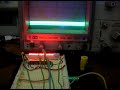
You can find some code examples that demonstrate the use of the accelerometer, RGB LED and touch sensor here. Here’s a quick video of the touch sensor in action:
So which pin is what on the Freedom board with respect to the mbed IDE? Review the following map:
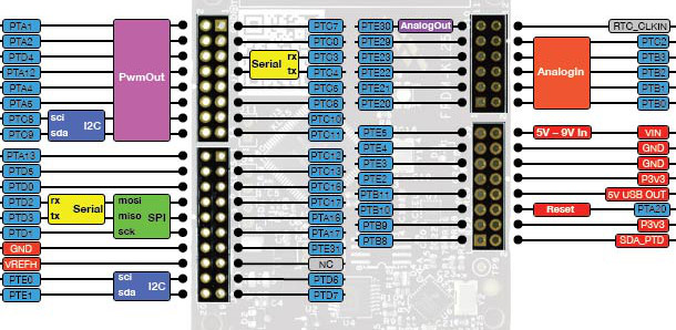
All the pins in blue – such as PTxx can be referred to in your code. For example, to pulse PTA13 on and off every second, use:
#include "mbed.h"
DigitalOut pulsepin(PTA13);
int main() {
 while(1) {
 pulsepin = 1;
 wait(1);
 pulsepin = 0;
 wait(1);
 }
}
The pin reference is inserted in the DigitalOut assignment and thus “pulsepin” refers to PTA13. If you don’t have the map handy, just turn the board over for a quick-reference (click to enlarge):

Just add “PT” to the pin number. Note that the LEDs are connected to existing GPIO pins: green – PTB19, red – PTB18 and blue – PTB.
Where to from here?
It’s up to you. Review the Freedom board manual (from here) and the documentation on the mbed website, create new things and possibly share them with others via the mbed environment. For more technical details review the MCU data sheet.
Conclusion
The Freedom board offers a very low cost way to get into microcontrollers and programming. You don’t have to worry about IDE or firmware revisions, installing software on locked-down computers, or losing files. You could teach a classroom full of children embedded programming for around $20 a head (a board and some basic components). Hopefully this short tutorial was of interest. We haven’t explored every minute detail – but you now have the basic understanding to move forward with your own explorations.
The Freescale Freedom FRDM-KL25Z development board used in this article was a promotional consideration supplied by element14.


 David J Hicks, http://www.hpmuseum.org/")