Like many of us, [Michael] needed a way to let the family know whether pants are required to enter the room — in other words, whenever a videoconference is in progress. Sure he could hang a do not disturb sign, but those are easy to forget. There’s no need to worry about forgetting to change status because this beautiful wall-mounted sign can be controlled with Alexa.
Inside the gorgeous box made from walnut, curly maple, and oak is an ESP32, some RGB LEDs, and three MOSFETs. [Michael] is using the fauxmoESP library to interface the ESP32 with Alexa, which emulates a Phillips Hue bulb for the sake of using a protocol she already knows. [Michael] can change the color and brightness percentage with voice commands.
The sign is set up as four different devices — one default, and one for each color. Since talking to Alexa isn’t always appropriate, [Michael] can also change the color of the LEDs using sliders on a website that’s served up by the ESP. Check out the full build video after the break.
The basic 16×2 LCD is an extremely popular component that we’ve seen used in more projects than we could possibly count. Part of that is because modern microcontrollers make it so easy to work with; if you’ve got an I2C variant of the display, it only takes four wires to drive it. That puts printing a line of text on one of these LCDs a step or two above blinking an LED on a digital pin on the hierarchy of beginner’s electronics projects.
What’s that? Even four wires is too many? In that case, you might be interested in this hack from [Vinod] which shows how you can drive the classic 16×2 with data and power on the same pair of wires. You’ll still need a microcontroller “backpack” for the LCD to interpret the modulated voltage, but if you’ve got an application for a simple remote display, this is definitely worth checking out.
The basic idea is to “blink” the 5 V line so quick that a capacitor on the LCD side can float the electronics over the dips in voltage. As long as one of the pins of the microcontroller is connected to the 5 V line before the capacitor, it will be able to pick up when the line goes low. With a high enough data rate and a large enough capacitor as a buffer, you’re well on the way to encoding your data to be displayed.
For the transmitting side, [Vinod] is using a Python script on his computer that’s sending out the text for the LCD over a standard USB to UART converter. That’s fed into a small circuit put together on a scrap of perfboard that triggers a MOSFET off of the UART TX line.
Beyond pride, the biggest issue keeping adults off small motorized scooters is the fact that their tiny motors usually don’t have the power to move anything heavier than your average eighth grader. That didn’t stop [The_Didlyest] from snapping up this $7 thrift store find, but it did mean the hot pink scooter would need to be beefed up if it had any hope of moving 170 lbs of hacker.
Logically, the first step was fitting a more capable motor. [The_Didlyest] used an electric wheelchair motor which had a similar enough diameter that mounting it was fairly straightforward. The original sprocket and chain are still used, as are the mounting holes in the frame (though they had to be tapped to a larger size). That said, the new motor is considerably longer than its predecessor so some frame metal had to be cut away. This left the scooter without a kickstand and with a few inches of motor hanging out of its left side, but it’s all in the name of progress.
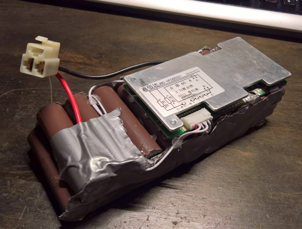
Naturally the upgraded motor needed similarly upgraded batteries to power it, so [The_Didlyest] put together a custom pack using eighteen 18650 cells spot welded together for a total output of 25V. Coupled with a 60A battery management system (BMS), the final 6S 3P configured pack is a very professional little unit, though the liberal application of duct tape keeps it from getting too full of itself.
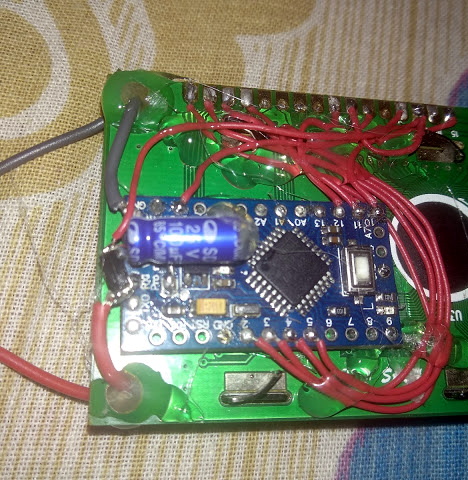
Unfortunately the original motor controller consisted of nothing but relays, and didn’t allow adjusting speed. So that needed to go as well. In its place is a homebrew speed controller made with three parallel MOSFETs and an Arduino to read the analog value from the throttle and convert that into a PWM signal.
[The_Didlyest] says the rear tire is now in need of an upgrade to transmit all this new power to the road, and some gearing might be in order, but otherwise the scooter rebuild was a complete success. Capable of mastering hills and with a top speed of about 10 MPH, the performance is certainly better than the stock hardware.
A classic one-man band generally features a stringed instrument or two, a harmonica in a hands-free holder, and some kind of percussion, usually a bass drum worn like a backpack and maybe some cymbals between the knees. The musician might also knock or tap the sound-boards of stringed instruments percussively with their strumming hand, which is something classical and flamenco guitarists can pull off with surprising range.
The musician usually has to manipulate each instrument manually. When it comes to percussion, [JimRD] has another idea: keep the beat by pounding the soundboard with a solenoid. He built a simple Arduino-driven MOSFET circuit to deliver knocks of variable BPM to the sound-board of a ukulele. A 10kΩ pot controls the meter and beat frequency, and the sound is picked up by a mic on the bridge. So far, it does 3/4 and 4/4 time, but [JimRD] has made the code freely available for expansion. Somebody make it do 5/4, because we’d love to hear [JimRD] play “Take Five“.
He didn’t do this to his good uke, mind you—it’s an old beater that he didn’t mind drilling and gluing. We were a bit skeptical at first, but the resonance sweetens the electromechanical knock of the solenoid slug. That, and [JimRD] has some pretty good chops. Ax your way past the break to give it a listen.
The Raspberry Pi and other similar Linux-based single board computers simplify many projects. However, one issue with Linux is that it doesn’t like being turned off abruptly. Things have gotten better, and you can certainly configure things to minimize the risk, but–in general–shutting a Linux system down while it is running will eventually lead to file system corruption.
If your project has an interface, you can always provide a shutdown option, but that doesn’t help if your application is headless. You can provide a shutdown button, but that leaves the problem of turning the device back on.
[Ivan] solved this problem with–what else–an Arduino (see the video below). Simplistically, the Arduino reads a button and uses a FET to turn off the power to the Pi. The reason for the Arduino, is that the tiny processor (which draws less than a Pi and doesn’t mind being shut down abruptly) can log into the Pi and properly shut it down. The real advantage, though, is that you could use other Arduino inputs to determine when to turn the Pi on and off.
For example, it is easy to imagine a Pi in an automotive application where the Arduino would sense the ignition was off for a certain period of time and then go ahead and shut off the Pi. Or maybe the Pi needs to be turned on when a motion sensor fires and then turned off again once there is no motion for a particular time period. Any of these strategies would be simple to build with the Arduino.
We’ve seen a similar project that used an IR remote as the trigger instead of a physical button. If you are afraid the Pi will just lose power unexpectedly, you might consider a battery backup. If powering a Pi with regular electricity is too tame for you, try steam.
A few weeks ago I found a DIODER LED strip set from a long-ago trek to IKEA, and considered that something could be done with it. So in this article you can see how easy it is to control the LEDs using an Arduino or compatible board with ease… opening it up to all sorts of possibilities.
This is not the most original project – however things have been pretty quiet around here, so I thought it was time to share something new with you. Furthermore the DIODER control PCB has changed, so this will be relevant to new purchases. Nevertheless, let’s get on with it.
So what is DIODER anyhow?
As you can see in the image below, the DIODER pack includes four RGB LED units each with nine RGB LEDs per unit. A controller box allows power and colour choice, a distribution box connects between the controller box and the LED strips, and the whole thing is powered by a 12V DC plugpack:
The following is a quick video showing the DIODER in action as devised by IKEA:
Thankfully the plugpack keeps us away from mains voltages, and includes a long detachable cable which connects to the LED strip distribution box. The first thought was to investigate the controller, and you can open it with a standard screwdriver. Carefully pry away the long-side, as two clips on each side hold it together…
… which reveals the PCB. Nothing too exciting here – you can see the potentiometer used for changing the lighting effects, power and range buttons and so on:
Our DIODER has the updated PCB with the Chinese market microcontroller. If you have an older DIODER with a Microchip PIC – you can reprogram it yourself.
The following three MOSFETs are used to control the current to each of the red, green and blue LED circuits. These will be the key to controlling the DIODER’s strips – but are way too small for me to solder to. The original plan was to have an Arduino’s PWM outputs tap into the MOSFET’s gates – but instead I will use external MOSFETs.
So what’s a MOSFET?
In the past you may have used a transistor to switch higher current from an Arduino, however a MOSFET is a better solution for this function. The can control large voltages and high currents without any effort. We will use N-channel MOSFETs, which have three pins – Source, Drain and Gate. When the Gate is HIGH, current will flow into the Drain and out of the Source:
A simplistic explanation is that it can be used like a button – and when wiring your own N-MOSFET a 10k resistor should be used between Gate and Drain to keep the Gate low when the Arduino output is set to LOW (just like de-bouncing a button). To learn more about MOSFETS – get yourself a copy of “The Art of Electronics“. It is worth every cent.
However being somewhat time poor (lazy?), I have instead used a Freetronics NDrive Shield for Arduino – which contains six N-MOSFETs all on one convenient shield – with each MOSFET’s Gate pin connected to an Arduino PWM output.
So let’s head back to the LED strips for a moment, in order to determine how the LEDs are wired in the strip. Thanks to the manufacturer – the PCB has the markings as shown below:
They’re 12V LEDs in a common-anode configuration. How much current do they draw? Depends on how many strips you have connected together…
For the curious I measured each colour at each length, with the results in the following table:
So all four strips turned on, with all colours on – the strips will draw around 165 mA of current at 12V. Those blue LEDs are certainly thirsty.
Moving on, the next step is to connect the strips to the MOSFET shield. This is easy thanks to the cable included in the DIODER pack, just chop the white connector off as shown below:
By connecting an LED strip to the other end of the cable you can then determine which wire is common, and which are the cathodes for red, green and blue.
The plugpack included with the DIODER pack can be used to power the entire project, so you will need cut the DC plug (the plug that connects into the DIODER’s distribution box) off the lead, and use a multimeter to determine which wire is negative, and which is positive.
Connect the negative wire to the GND terminal on the shield, and the positive wire to the Vin terminal. Then…
the red LED wire to the D3 terminal,
the green LED wire to the D9 terminal,
and the blue LED wire to the D10 terminal.
Finally, connect the 12V LED wire (anode) into the Vin terminal. Now double-check your wiring. Then check it again.
Testing
Now to run a test sketch to show the LED strip can easily be controlled. We’ll turn each colour on and off using PWM (Pulse-Width Modulation) – a neat way to control the brightness of each colour. The following sketch will pulse each colour in turn, and there’s also a blink function you can use.
// Controlling IKEA DIODER LED strips with Arduino and Freetronics NDRIVE N-MOSFET shield
// CC by-sa-nc John Boxall 2015 - tronixstuff.com
// Components from tronixlabs.com

#define red 3
#define green 9
#define blue 10
#define delaya 2

void setup()
{
  pinMode(red, OUTPUT);
  pinMode(green, OUTPUT);
  pinMode(blue, OUTPUT);
}

void blinkRGB()
{
  digitalWrite(red, HIGH);
  delay(1000);
  digitalWrite(red, LOW);
  digitalWrite(green, HIGH);
  delay(1000);
  digitalWrite(green, LOW);
  digitalWrite(blue, HIGH);
  delay(1000);
  digitalWrite(blue, LOW);
}

void pulseRed()
{
  for (int i=0; i<256; i++)
  {
    analogWrite(red,i);
    delay(delaya);
  }
  for (int i=255; i>=0; --i)
  {
    analogWrite(red,i);
    delay(delaya);
  }
}

void pulseGreen()
{
  for (int i=0; i<256; i++)
  {
    analogWrite(green,i);
    delay(delaya);
  }
  for (int i=255; i>=0; --i)
  {
    analogWrite(green,i);
    delay(delaya);
  }
}

void pulseBlue()
{
  for (int i=0; i<256; i++)
  {
    analogWrite(blue,i);
    delay(delaya);
  }
  for (int i=255; i>=0; --i)
  {
    analogWrite(blue,i);
    delay(delaya);
  }
}

void loop()
{
  pulseRed();
  pulseGreen();
  pulseBlue();
}
As always, there’s a better way of doing things and one example of LED control is the awesome FASTLED library by Daniel Garcia and others. Go and download it now – https://github.com/FastLED/FastLED. Apart from our simple LEDS, the FASTLED library is also great with WS2812B/Adafruit NeoPixels and others.
One excellent demonstration included with the library is the AnalogOutput sketch, which I have supplied below to work with our example hardware:
#include <FastLED.h>

// Example showing how to use FastLED color functions
// even when you're NOT using a "pixel-addressible" smart LED strip.
//
// This example is designed to control an "analog" RGB LED strip
// (or a single RGB LED) being driven by Arduino PWM output pins.
// So this code never calls FastLED.addLEDs() or FastLED.show().
//
// This example illustrates one way you can use just the portions
// of FastLED that you need.  In this case, this code uses just the
// fast HSV color conversion code.
//
// In this example, the RGB values are output on three separate
// 'analog' PWM pins, one for red, one for green, and one for blue.

#define REDPIN   3
#define GREENPIN 9
#define BLUEPIN  10

// showAnalogRGB: this is like FastLED.show(), but outputs on
// analog PWM output pins instead of sending data to an intelligent,
// pixel-addressable LED strip.
//
// This function takes the incoming RGB values and outputs the values
// on three analog PWM output pins to the r, g, and b values respectively.
void showAnalogRGB( const CRGB& rgb)
{
  analogWrite(REDPIN,   rgb.r );
  analogWrite(GREENPIN, rgb.g );
  analogWrite(BLUEPIN,  rgb.b );
}


// colorBars: flashes Red, then Green, then Blue, then Black.
// Helpful for diagnosing if you've mis-wired which is which.
void colorBars()
{
  showAnalogRGB( CRGB::Red );   delay(500);
  showAnalogRGB( CRGB::Green ); delay(500);
  showAnalogRGB( CRGB::Blue );  delay(500);
  showAnalogRGB( CRGB::Black ); delay(500);
}

void loop()
{
  static uint8_t hue;
  hue = hue + 1;
  // Use FastLED automatic HSV->RGB conversion
  showAnalogRGB( CHSV( hue, 255, 255) );

  delay(20);
}


void setup() {
  pinMode(REDPIN,   OUTPUT);
  pinMode(GREENPIN, OUTPUT);
  pinMode(BLUEPIN,  OUTPUT);

  // Flash the "hello" color sequence: R, G, B, black.
  colorBars();
}
You can see this in action through the following video:
So if you have some IKEA LED strips, or anything else that requires more current than an Arduino’s output pin can offer – you can use MOSFETs to take over the current control and have fun. And finally a plug for my own store – tronixlabs.com – offering a growing range and Australia’s best value for supported hobbyist electronics from adafruit, DFRobot, Freetronics, Seeed Studio and much much more.
As always, have fun and keep checking into tronixstuff.com. Why not follow things on twitter, Google+, subscribe for email updates or RSS using the links on the right-hand column, or join our forum – dedicated to the projects and related items on this website.
arduino, mosfetComments Off on Super Simple Arduino Load Driver V2.0
Turn loads on and off with your Arduino! Use 5V to control up to 100V. Add a motor, solenoid, or get creative! P channel or N Channel.
This is version 2.0 of the previously successful kickstarter project I launched last year. I have a ton of these PCB boards left over and it got me thinking. Why not find a P channel MOSFET with the same pinout and use it to control the direction of the motor also. I looked around and found the IRF5210. I ordered up a batch and tested them out. All thats left to do now is order a large quantity for the price break and assemble the rest of the boards.
[Ashish] is bringing office warfare to the next level with a motion sensing water gun. Not only does this water gun automatically fire when it detects motion, but it also takes a photo of the victim and publishes it on Twitter.
This hack began with the watergun. [Ashish] used a Super Soaker Thunderstorm motorized water gun. He pulled the case apart and cut one of the battery wires. he then lengthened the exposed ends and ran them out of the gun to his control circuit. He also placed a protection diode to help prevent any reverse EMF from damaging his more sensitive electronics. The new control wires run to a MOSFET on a bread board.
[Ashish] is using a Lightblue Bean board as a microcontroller. The Bean is Arduino compatible and can be programmed via low energy Bluetooth. The Bean uses an external PIR sensor to detect motion in the room. When it senses the motion, it activates the MOSFET which then turns on the water gun.
[Ashish] decided to use Node-RED and Python to link the Bean to a Twitter account. The system runs on a computer and monitor’s the Bean’s serial output. If it detects the proper command, it launches a Python script which takes a photo using a webcam. A second script will upload that photo to a Twitter account. The Node-RED server can also monitor the Twitter account for incoming direct messages. If it detects a message with the correct password, it can use the rest of the message as a command to enable or disable the gun.
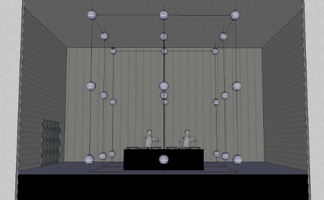
Cubled is an interactive installation made of 27 luminous spheres arranged in space to create a cube 5 mt (16.4ft) per side floating on a stage.
The project created by Giuseppe Acito of Opificio Sonico has a structure made of steel wires, RGB LED Strips and Ikea paper lanterns.
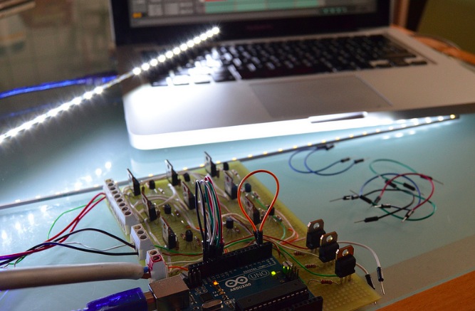
The system is MIDI-controlled, the notes generated by a sequencer are converted to electric signals using an Arduino UNO and a Mosfet:
No DMX device was used for this system which is 12V DC powered, with slim electric wires in order to give the lightness needed to this installation. In this clip, the performance is splitted in 2 parts: in the first a kit of electronic percussion is “played” live by a step sequencer named Sonic Fraction Beatdown (a MaxMSP device for Ableton Live), the combinations of 12 MIDI notes generated are linked to the spheres. In the second part the combinations of sounds and lights are pre-programmed patterns clip and performed live by a Tenori-on Yamaha and Ableton Live. The installation was mounted inside the Link Club (Bologna – Italy) in December 2013, which hosted some world-famous DJ set, during a month of permanence.
arduino, BLDC, L6234, mosfet, motorComments Off on Spining BLDC motors at super Slow speeds with Arduino and L6234
by berryjam.eu:
I used specialized triple half bridge IC L6234 (~ 8$). You can make the same spending less money (but more time) with MOSFET transistors or other IC.
L6234 datasheet is surprisingly useless. Go straight to Application Note AN1088 instead.
I added current limiting resistors (1kΩ) to all INputs and ENable pins, a bunch of capacitors recommended in application note and current sensing shunt resistor 0.6Ω (big blue one).
Spining BLDC motors at super Slow speeds with Arduino and L6234 - [Link]
Planet Arduino is, or at the moment is wishing to become, an aggregation of public weblogs from around the world written by people who develop, play, think on Arduino platform and his son. The opinions expressed in those weblogs and hence this aggregation are those of the original authors. Entries on this page are owned by their authors. We do not edit, endorse or vouch for the contents of individual posts. For more information about Arduino please visit www.arduino.cc
You are currently browsing the archives for the mosfet category.